EP0349979A1 - Disposition pour amortir les vibrations des constructions ou des parties de construction - Google Patents
Disposition pour amortir les vibrations des constructions ou des parties de construction Download PDFInfo
- Publication number
- EP0349979A1 EP0349979A1 EP89112197A EP89112197A EP0349979A1 EP 0349979 A1 EP0349979 A1 EP 0349979A1 EP 89112197 A EP89112197 A EP 89112197A EP 89112197 A EP89112197 A EP 89112197A EP 0349979 A1 EP0349979 A1 EP 0349979A1
- Authority
- EP
- European Patent Office
- Prior art keywords
- elements
- damping
- vibration
- friction spring
- vibrations
- Prior art date
- Legal status (The legal status is an assumption and is not a legal conclusion. Google has not performed a legal analysis and makes no representation as to the accuracy of the status listed.)
- Granted
Links
Images


Classifications
-
- E—FIXED CONSTRUCTIONS
- E04—BUILDING
- E04H—BUILDINGS OR LIKE STRUCTURES FOR PARTICULAR PURPOSES; SWIMMING OR SPLASH BATHS OR POOLS; MASTS; FENCING; TENTS OR CANOPIES, IN GENERAL
- E04H9/00—Buildings, groups of buildings or shelters adapted to withstand or provide protection against abnormal external influences, e.g. war-like action, earthquake or extreme climate
- E04H9/02—Buildings, groups of buildings or shelters adapted to withstand or provide protection against abnormal external influences, e.g. war-like action, earthquake or extreme climate withstanding earthquake or sinking of ground
- E04H9/021—Bearing, supporting or connecting constructions specially adapted for such buildings
- E04H9/0215—Bearing, supporting or connecting constructions specially adapted for such buildings involving active or passive dynamic mass damping systems
Definitions
- the invention relates to an arrangement for damping vibrations on structures or components, consisting of a damper mass which is connected to the structure or component via resilient and vibration-damping elements.
- the known dynamic vibration dampers consist of a damper mass that oscillates or via a vibration element, e.g. an axially loaded rubber element is attached to the structure or component and its oscillating or oscillating movement through special damping elements, e.g. in the manner of motor vehicle vibration dampers (DE-OS 27 18 962) or with wire rope coil springs (DE-PS 28 06 757) is damped.
- a vibration element e.g. an axially loaded rubber element is attached to the structure or component and its oscillating or oscillating movement through special damping elements, e.g. in the manner of motor vehicle vibration dampers (DE-OS 27 18 962) or with wire rope coil springs (DE-PS 28 06 757) is damped.
- vibration dampers that are largely wear-free and low-maintenance and have clearly defined non-linear characteristics, so that a clear calculation is possible.
- a vibration-damping arrangement is desirable, the natural frequency of which can be varied over one and the same element over a larger frequency range.
- the invention is therefore based on the object of making an arrangement of the generic type in such a way that the abovementioned favorable properties are achieved.
- friction spring elements are provided as resilient and vibration-damping elements, which are arranged radially, tangentially and / or perpendicular to the direction of the vibrations to be damped on the structure or component.
- a pendulum suspension of the damper mass is selected with pendulum rods or angle levers, which allows any arrangement of the friction spring elements. This results in a wide range of the adjustable natural frequency of the vibration damper and a large variation in the design. Furthermore, the susceptibility to faults and the need for maintenance is very low.
- the suspension and damping properties of the friction spring elements can be adjusted by the type, number and preload of the ring elements. Furthermore, a large non-linearity of the friction spring element can be achieved through the free choice of the preload. As a result, a larger frequency range can be covered when the element is set.
- the structure or component equipped with a vibration damper according to the invention is primarily designed so that the damper mass is suspended on pendulum rods and the damper mass is supported on the ring spring elements via the rods.
- Another embodiment is the suspension on angle levers, which are articulated.
- the damper mass is supported indirectly via the friction spring elements.
- the reaction to the structure is transmitted through the upper suspension.
- a stepless change in the lever arms can be achieved by the arrangement of the friction spring elements and a stepless power transmission can be achieved by changing the inclination of the elements to the lever. This range of variation has a great advantage. If previous calculations for the structure or component are incorrect due to incorrect information, particularly with regard to the relevant natural frequencies and the reduced dynamic replacement masses, or if changes have occurred to the structure, the vibration damper must be adjusted to the new design values without any particular effort.
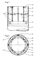
- the dynamic vibration dampers according to the invention can be inside or outside of a building 1, e.g. Antenna support, chimney or mast can be attached.
- Brackets 6, to which pendulum rods 4 or angle levers 4a are articulated, are fastened to the structure 1 diametrically opposite one another.
- These pendulum rods 4 or angle levers 4a take up the weight of the damper mass 2, which can have the shape of a closed or open circular ring or polygonal ring, for example.
- Both resilient and damping friction spring elements 3 are arranged between the pendulum rods 4 or the angle levers 4a and the structure 1. These elements 3 can engage at any point on the pendulum rods 4 or the angle lever 4a and on the building-side fastening strips 5. They are connected by suitable articulated connections 7, for example ball joints with fork heads and bolts, to the pendulum rods 4 or the angle levers 4a and the coupling strips 5.
- the friction spring elements 3 have a damping in their ring elements due to the friction and an adjustable, precisely determinable spring characteristic due to the composition (type, number) and the preload. It is also advantageous that the resilient and damping properties of the friction spring element 3 are independent of the oscillation speed, oscillation frequency and temperature.
- the elements 3 are also corrosion-resistant and practically maintenance-free. Due to the shape of the arrangement, they take up little space. Due to the very variable arrangement of the friction spring elements 3, a damper design can be tuned to any natural frequency within the framework of the specified geometry, i.e. a change in the natural damper frequency is possible at any time.
- the friction spring element 3 is essentially formed from outer rings 3a and axially slotted inner rings 3b, which interact via conical contact surfaces and are arranged within a housing 3c, 3d.
- the housing has a fastening eye 3e at the ends of its two telescoping housing parts 3c and 3d.
- a central screw 3f is used to adjust the preload of the friction spring element 3.
- the friction spring element 3 can also be stressed by suitable articulation in the pulling and pushing directions.
- a modification, not shown, for example FIGS. 1 and 2 may consist in replacing some friction spring elements 3 by articulated, rigid connecting parts. Deviating from the exemplary embodiments shown, it is also entirely possible to arrange friction spring elements 3 radially between the structure 1 and the damper mass 2. Combinations of radial, tangential and vertical arrangements of friction spring elements 3; For example, in addition to the friction spring elements 3 lying tangentially in FIGS. 1 and 2 or to the friction spring elements 3 standing vertically according to FIG. 3, friction spring elements 3 can also be arranged radially.
Landscapes
- Engineering & Computer Science (AREA)
- Architecture (AREA)
- Business, Economics & Management (AREA)
- Emergency Management (AREA)
- Environmental & Geological Engineering (AREA)
- Civil Engineering (AREA)
- Structural Engineering (AREA)
- Vibration Prevention Devices (AREA)
- Buildings Adapted To Withstand Abnormal External Influences (AREA)
Applications Claiming Priority (2)
| Application Number | Priority Date | Filing Date | Title |
|---|---|---|---|
| DE3823206 | 1988-07-08 | ||
| DE3823206A DE3823206A1 (de) | 1988-07-08 | 1988-07-08 | Anordnung zur daempfung von schwingungen an bauwerken oder bauteilen |
Publications (2)
| Publication Number | Publication Date |
|---|---|
| EP0349979A1 true EP0349979A1 (fr) | 1990-01-10 |
| EP0349979B1 EP0349979B1 (fr) | 1991-10-23 |
Family
ID=6358280
Family Applications (1)
| Application Number | Title | Priority Date | Filing Date |
|---|---|---|---|
| EP89112197A Expired - Lifetime EP0349979B1 (fr) | 1988-07-08 | 1989-07-04 | Disposition pour amortir les vibrations des constructions ou des parties de construction |
Country Status (2)
| Country | Link |
|---|---|
| EP (1) | EP0349979B1 (fr) |
| DE (2) | DE3823206A1 (fr) |
Cited By (5)
| Publication number | Priority date | Publication date | Assignee | Title |
|---|---|---|---|---|
| DE4305132C1 (de) * | 1993-02-19 | 1994-04-21 | Uwe E Dr Dorka | Reibungsdämpfer zur Sicherung von Tragwerken gegen dynamische Einwirkungen |
| FR2698896A1 (fr) * | 1992-12-09 | 1994-06-10 | Oudin Gilles | Dispositif d'atténuation des oscillations d'ouvrages ou structures, notamment d'ouvrages élancés tels que des cheminées, pylônes, mâts et ouvrages analogues. |
| EP0543228B2 (fr) † | 1991-11-18 | 2003-07-09 | Bayer Ag | Combinaison aqueuse de liants et leur utilisation |
| AT510170B1 (de) * | 2010-11-10 | 2012-02-15 | Penz Alois | Turmartiges, hohles bauwerk, insbesondere aufwindkamin |
| US20200284240A1 (en) * | 2017-08-08 | 2020-09-10 | Fm Energie Gmbh & Co. Kg | Rotation dampers and vibration absorbers equipped therewith |
Families Citing this family (6)
| Publication number | Priority date | Publication date | Assignee | Title |
|---|---|---|---|---|
| DE4009893A1 (de) * | 1990-03-28 | 1991-10-02 | Dietrich Fette | Schwingungstilger fuer schlanke bauwerke |
| DE4231725C2 (de) * | 1992-09-22 | 1995-11-09 | Selkirk Schornsteintechnik Gmb | Vorrichtung zur Dämpfung von Schwingungen an freistehenden Bauwerken |
| DE4231729C2 (de) * | 1992-09-22 | 1995-09-28 | Selkirk Schornsteintechnik Gmb | Vorrichtung zur Dämpfung von Schwingungen an freistehenden Bauwerken |
| US5819484A (en) * | 1995-07-28 | 1998-10-13 | Kar; Ramapada | Building structure with friction based supplementary damping in its bracing system for dissipating seismic energy |
| DE102007024431A1 (de) | 2007-05-25 | 2008-11-27 | Dr. Ing. H.C. F. Porsche Aktiengesellschaft | Vorrichtung zum Dämpfen von Schwingungen |
| CN106812227A (zh) * | 2017-03-23 | 2017-06-09 | 南通市苏东钢结构有限公司 | 一种分级隔减震器 |
Citations (3)
| Publication number | Priority date | Publication date | Assignee | Title |
|---|---|---|---|---|
| DE2551471A1 (de) * | 1975-11-15 | 1977-10-06 | Maurer Friedrich Soehne | Einrichtung zur schwingungsdaempfung an ueberschlanken bauwerken |
| DE2806757A1 (de) * | 1978-02-17 | 1979-08-23 | Ka Be Werk Lufttechnik Und Ent | Dynamischer schwingungsdaempfer zur anbringung an bauwerken |
| GB2040429A (en) * | 1979-01-17 | 1980-08-28 | Nat Res Dev | Improvements in or relating to stabilising structures against oscillation |
Family Cites Families (1)
| Publication number | Priority date | Publication date | Assignee | Title |
|---|---|---|---|---|
| NL287625A (fr) * | 1962-05-23 |
-
1988
- 1988-07-08 DE DE3823206A patent/DE3823206A1/de not_active Withdrawn
-
1989
- 1989-07-04 EP EP89112197A patent/EP0349979B1/fr not_active Expired - Lifetime
- 1989-07-04 DE DE8989112197T patent/DE58900398D1/de not_active Expired - Lifetime
Patent Citations (3)
| Publication number | Priority date | Publication date | Assignee | Title |
|---|---|---|---|---|
| DE2551471A1 (de) * | 1975-11-15 | 1977-10-06 | Maurer Friedrich Soehne | Einrichtung zur schwingungsdaempfung an ueberschlanken bauwerken |
| DE2806757A1 (de) * | 1978-02-17 | 1979-08-23 | Ka Be Werk Lufttechnik Und Ent | Dynamischer schwingungsdaempfer zur anbringung an bauwerken |
| GB2040429A (en) * | 1979-01-17 | 1980-08-28 | Nat Res Dev | Improvements in or relating to stabilising structures against oscillation |
Non-Patent Citations (1)
| Title |
|---|
| PATENT ABSTRACTS OF JAPAN, Band 8, Nr. 210 (M-328)[1647], 26. September 1984; & JP-A-59 97 342 (NIPPON KOKAN K.K.) 05-06-1984 * |
Cited By (8)
| Publication number | Priority date | Publication date | Assignee | Title |
|---|---|---|---|---|
| EP0543228B2 (fr) † | 1991-11-18 | 2003-07-09 | Bayer Ag | Combinaison aqueuse de liants et leur utilisation |
| FR2698896A1 (fr) * | 1992-12-09 | 1994-06-10 | Oudin Gilles | Dispositif d'atténuation des oscillations d'ouvrages ou structures, notamment d'ouvrages élancés tels que des cheminées, pylônes, mâts et ouvrages analogues. |
| DE4305132C1 (de) * | 1993-02-19 | 1994-04-21 | Uwe E Dr Dorka | Reibungsdämpfer zur Sicherung von Tragwerken gegen dynamische Einwirkungen |
| AT510170B1 (de) * | 2010-11-10 | 2012-02-15 | Penz Alois | Turmartiges, hohles bauwerk, insbesondere aufwindkamin |
| AT510170A4 (de) * | 2010-11-10 | 2012-02-15 | Penz Alois | Turmartiges, hohles bauwerk, insbesondere aufwindkamin |
| WO2012061859A3 (fr) * | 2010-11-10 | 2012-07-12 | Alois Penz | Structure creuse de type tour, en particulier cheminée à courant d'air ascendant |
| US20200284240A1 (en) * | 2017-08-08 | 2020-09-10 | Fm Energie Gmbh & Co. Kg | Rotation dampers and vibration absorbers equipped therewith |
| US11603821B2 (en) * | 2017-08-08 | 2023-03-14 | Fm Energie Gmbh & Co. Kg | Rotation damper and vibration absorber equipped therewith |
Also Published As
| Publication number | Publication date |
|---|---|
| DE58900398D1 (de) | 1991-11-28 |
| DE3823206A1 (de) | 1990-01-11 |
| EP0349979B1 (fr) | 1991-10-23 |
Similar Documents
| Publication | Publication Date | Title |
|---|---|---|
| DE69631871T2 (de) | Schwingungsdämpfer für Hubschrauberrotor-System | |
| EP2673531B1 (fr) | Montage sans vibrations d'un objet sur une structure | |
| EP0349979B1 (fr) | Disposition pour amortir les vibrations des constructions ou des parties de construction | |
| EP3610172A1 (fr) | Amortissement des vibrations d'une tour de centrale éolienne | |
| AT516245B1 (de) | Unterbaukonstruktion zur Erhöhung der Erdbebensicherheit eines Hochspannungsbauteils | |
| DE2806757C3 (de) | Anordnung zur Dämpfung von Schwingungen an Bauwerken | |
| DE3113268A1 (de) | "schwingungsabsorber" | |
| DE102010038782A1 (de) | Drehschwingungstilger mit zweiarmigem Pendel | |
| EP3433509B1 (fr) | Pendule d'amortissement tridimensionnel compact avec trajectoire ellïpsoidale | |
| DE3827329A1 (de) | Drehmomentabstuetzung fuer auf wellenzapfen reitende antriebe, insbesondere fuer konverterkippantriebe | |
| DE19715714A1 (de) | Dämpferelement und damit versehene Dämpfungseinheit | |
| DE3816033C2 (fr) | ||
| DE10233023B3 (de) | Schwingungsisolator | |
| DE3414706C2 (fr) | ||
| DE3003042C2 (de) | Anordnung zum Dämpfen von Windschwingungen auf einer Freileitung | |
| DE202012105031U1 (de) | In einer Achse stoß- und schwingungsfreie Lagerung | |
| DE1278581B (de) | Schwingungsdaempfer fuer Freileitungen | |
| DE19711846C2 (de) | Mechanischer Schwingungstilger | |
| DE4231729C2 (de) | Vorrichtung zur Dämpfung von Schwingungen an freistehenden Bauwerken | |
| DE3243168C2 (fr) | ||
| EP0240572A1 (fr) | Unite de prevention contre les tremblements de terre | |
| DE3935893A1 (de) | Daempfung von dynamischen instabilitaeten | |
| DE102017218641A1 (de) | Schwingungstilger, insbesondere für einen Schaltschrank | |
| EP0349978B1 (fr) | Disposition d'amortissement des oscillations de systèmes élastiques | |
| DE1056431B (de) | Federnde Aufhaengung fuer axial bewegliche, zylindrische Lager |
Legal Events
| Date | Code | Title | Description |
|---|---|---|---|
| PUAI | Public reference made under article 153(3) epc to a published international application that has entered the european phase |
Free format text: ORIGINAL CODE: 0009012 |
|
| AK | Designated contracting states |
Kind code of ref document: A1 Designated state(s): CH DE FR GB IT LI NL |
|
| 17P | Request for examination filed |
Effective date: 19900122 |
|
| 17Q | First examination report despatched |
Effective date: 19901029 |
|
| GRAA | (expected) grant |
Free format text: ORIGINAL CODE: 0009210 |
|
| AK | Designated contracting states |
Kind code of ref document: B1 Designated state(s): CH DE FR GB IT LI NL |
|
| ET | Fr: translation filed | ||
| REF | Corresponds to: |
Ref document number: 58900398 Country of ref document: DE Date of ref document: 19911128 |
|
| GBT | Gb: translation of ep patent filed (gb section 77(6)(a)/1977) | ||
| ITF | It: translation for a ep patent filed |
Owner name: SOCIETA' ITALIANA BREVETTI S.P.A. |
|
| PLBE | No opposition filed within time limit |
Free format text: ORIGINAL CODE: 0009261 |
|
| STAA | Information on the status of an ep patent application or granted ep patent |
Free format text: STATUS: NO OPPOSITION FILED WITHIN TIME LIMIT |
|
| 26N | No opposition filed | ||
| REG | Reference to a national code |
Ref country code: GB Ref legal event code: IF02 |
|
| PGFP | Annual fee paid to national office [announced via postgrant information from national office to epo] |
Ref country code: FR Payment date: 20020610 Year of fee payment: 14 |
|
| PGFP | Annual fee paid to national office [announced via postgrant information from national office to epo] |
Ref country code: GB Payment date: 20020612 Year of fee payment: 14 |
|
| PGFP | Annual fee paid to national office [announced via postgrant information from national office to epo] |
Ref country code: CH Payment date: 20020617 Year of fee payment: 14 |
|
| PGFP | Annual fee paid to national office [announced via postgrant information from national office to epo] |
Ref country code: NL Payment date: 20020619 Year of fee payment: 14 Ref country code: DE Payment date: 20020619 Year of fee payment: 14 |
|
| PG25 | Lapsed in a contracting state [announced via postgrant information from national office to epo] |
Ref country code: GB Free format text: LAPSE BECAUSE OF NON-PAYMENT OF DUE FEES Effective date: 20030704 |
|
| PG25 | Lapsed in a contracting state [announced via postgrant information from national office to epo] |
Ref country code: LI Free format text: LAPSE BECAUSE OF NON-PAYMENT OF DUE FEES Effective date: 20030731 Ref country code: CH Free format text: LAPSE BECAUSE OF NON-PAYMENT OF DUE FEES Effective date: 20030731 |
|
| PG25 | Lapsed in a contracting state [announced via postgrant information from national office to epo] |
Ref country code: NL Free format text: LAPSE BECAUSE OF NON-PAYMENT OF DUE FEES Effective date: 20040201 |
|
| PG25 | Lapsed in a contracting state [announced via postgrant information from national office to epo] |
Ref country code: DE Free format text: LAPSE BECAUSE OF NON-PAYMENT OF DUE FEES Effective date: 20040203 |
|
| GBPC | Gb: european patent ceased through non-payment of renewal fee |
Effective date: 20030704 |
|
| REG | Reference to a national code |
Ref country code: CH Ref legal event code: PL |
|
| PG25 | Lapsed in a contracting state [announced via postgrant information from national office to epo] |
Ref country code: FR Free format text: LAPSE BECAUSE OF NON-PAYMENT OF DUE FEES Effective date: 20040331 |
|
| NLV4 | Nl: lapsed or anulled due to non-payment of the annual fee |
Effective date: 20040201 |
|
| REG | Reference to a national code |
Ref country code: FR Ref legal event code: ST |
|
| PG25 | Lapsed in a contracting state [announced via postgrant information from national office to epo] |
Ref country code: IT Free format text: LAPSE BECAUSE OF NON-PAYMENT OF DUE FEES;WARNING: LAPSES OF ITALIAN PATENTS WITH EFFECTIVE DATE BEFORE 2007 MAY HAVE OCCURRED AT ANY TIME BEFORE 2007. THE CORRECT EFFECTIVE DATE MAY BE DIFFERENT FROM THE ONE RECORDED. Effective date: 20050704 |