EP0349979A1 - Arrangement for damping vibrations of structures or parts thereof - Google Patents
Arrangement for damping vibrations of structures or parts thereof Download PDFInfo
- Publication number
- EP0349979A1 EP0349979A1 EP89112197A EP89112197A EP0349979A1 EP 0349979 A1 EP0349979 A1 EP 0349979A1 EP 89112197 A EP89112197 A EP 89112197A EP 89112197 A EP89112197 A EP 89112197A EP 0349979 A1 EP0349979 A1 EP 0349979A1
- Authority
- EP
- European Patent Office
- Prior art keywords
- elements
- damping
- vibration
- friction spring
- vibrations
- Prior art date
- Legal status (The legal status is an assumption and is not a legal conclusion. Google has not performed a legal analysis and makes no representation as to the accuracy of the status listed.)
- Granted
Links
Images


Classifications
-
- E—FIXED CONSTRUCTIONS
- E04—BUILDING
- E04H—BUILDINGS OR LIKE STRUCTURES FOR PARTICULAR PURPOSES; SWIMMING OR SPLASH BATHS OR POOLS; MASTS; FENCING; TENTS OR CANOPIES, IN GENERAL
- E04H9/00—Buildings, groups of buildings or shelters adapted to withstand or provide protection against abnormal external influences, e.g. war-like action, earthquake or extreme climate
- E04H9/02—Buildings, groups of buildings or shelters adapted to withstand or provide protection against abnormal external influences, e.g. war-like action, earthquake or extreme climate withstanding earthquake or sinking of ground
- E04H9/021—Bearing, supporting or connecting constructions specially adapted for such buildings
- E04H9/0215—Bearing, supporting or connecting constructions specially adapted for such buildings involving active or passive dynamic mass damping systems
Landscapes
- Engineering & Computer Science (AREA)
- Architecture (AREA)
- Business, Economics & Management (AREA)
- Emergency Management (AREA)
- Environmental & Geological Engineering (AREA)
- Civil Engineering (AREA)
- Structural Engineering (AREA)
- Vibration Prevention Devices (AREA)
- Buildings Adapted To Withstand Abnormal External Influences (AREA)
Abstract
Description
Die Erfindung bezieht sich auf eine Anordnung zur Dämpfung von Schwingungen an Bauwerken oder Bauteilen, bestehend aus einer Dämpfermasse, die über federnde und schwingungsdämpfende Elemente mit dem Bauwerk oder Bauteil verbunden ist.The invention relates to an arrangement for damping vibrations on structures or components, consisting of a damper mass which is connected to the structure or component via resilient and vibration-damping elements.
Es ist bekannt, Bauwerke oder Bauteile, welche durch äußere Erregung zur Schwingung in der Grundfrequenz oder einer höheren Eigenfrequenz neigen und keine genügende Eigendämpfung besitzen, insbesondere Stahlkamine, Antennenträger, Pylone, Stützen, Seile oder Rohrleitungen, durch dynamische Schwingungsdämpfer vor Schäden zu bewahren. Die Erregung kann bei den genannten Bauwerken z.B. durch den Wind hervorgerufen sein oder seismischen Ursprung haben. Normalerweise bestehen die bekannten dynamischen Schwingungsdämpfer aus einer Dämpfermasse, die pendelnd oder über ein Schwingelement, z.B. ein axial belastetes Gummielement, am Bauwerk oder Bauteil angebracht ist und deren pendelnde bzw. schwingende Bewegung durch besondere Dämpfungselemente, z.B. nach Art von Kraftfahrzeug-Schwingungsdämpfern (DE-OS 27 18 962) oder mit Drahtseil-Schraubenfedern (DE-PS 28 06 757),gedämpft ist.It is known to protect buildings or components which tend to vibrate at the fundamental frequency or a higher natural frequency due to external excitation and do not have sufficient internal damping, in particular steel chimneys, antenna carriers, pylons, supports, ropes or pipelines, from damage by dynamic vibration dampers. The excitation can e.g. be caused by the wind or have seismic origin. Normally, the known dynamic vibration dampers consist of a damper mass that oscillates or via a vibration element, e.g. an axially loaded rubber element is attached to the structure or component and its oscillating or oscillating movement through special damping elements, e.g. in the manner of motor vehicle vibration dampers (DE-OS 27 18 962) or with wire rope coil springs (DE-PS 28 06 757) is damped.
Für die weitere Entwicklung auf diesem Gebiet kommt es insbesondere darauf an, Schwingungsdämpfer zu finden, die weitgehend verschleißfrei und wartungsarm sind und klar definierte nichtlineare Kennlinien aufweisen, so daß eine eindeutige Berechenbarkeit möglich ist. Weiter ist eine schwingungsdämpfende Anordnung wünschenswert, deren Eigenfrequenz mit ein und demselben Element über einen größeren Frequenzbereich variiert werden kann.For the further development in this area, it is particularly important to find vibration dampers that are largely wear-free and low-maintenance and have clearly defined non-linear characteristics, so that a clear calculation is possible. Furthermore, a vibration-damping arrangement is desirable, the natural frequency of which can be varied over one and the same element over a larger frequency range.
Der Erfindung liegt daher die Aufgabe zugrunde, eine Anordnung der gattungsgemäßen Art so vorzunehmen, daß die vorgenannten günstigen Eigenschaften erzielt werden.The invention is therefore based on the object of making an arrangement of the generic type in such a way that the abovementioned favorable properties are achieved.
Diese Aufgabe wird erfindungsgemäß dadurch gelöst, daß als federnde und schwingungsdämpfende Elemente Reibungsfeder-Elemente vorgesehen sind, die radial, tangential und/oder senkrecht zur Richtung der zu dämpfenden Schwingungen am Bauwerk oder Bauteil angeordnet sind.This object is achieved in that friction spring elements are provided as resilient and vibration-damping elements, which are arranged radially, tangentially and / or perpendicular to the direction of the vibrations to be damped on the structure or component.
Bei der Erfindung wird eine pendelnde Aufhängung der Dämpfermasse mit Pendelstangen oder Winkelhebeln gewählt, die eine beliebige Anordnung der Reibungsfeder-Elemente erlaubt. Dadurch ergibt sich eine große Bandbreite der einstellbaren Eigenfrequenz des Schwingungsdämpfers und eine große Variation in der Ausführung. Ferner ist die Störanfälligkeit und Wartungsbedürftigkeit sehr gering.In the invention, a pendulum suspension of the damper mass is selected with pendulum rods or angle levers, which allows any arrangement of the friction spring elements. This results in a wide range of the adjustable natural frequency of the vibration damper and a large variation in the design. Furthermore, the susceptibility to faults and the need for maintenance is very low.
In bevorzugter Ausgestaltung der Erfindung sind die Federungs- und Dämpfungseigenschaften der Reibungsfeder-Elemente durch Art, Anzahl und Vorspannung der Ringelemente einstellbar. Ferner kann durch die freie Wahl der Vorspannung eine große Nichtlinearität des Reibungsfeder-Elements erreicht werden. Dadurch kann ein größerer Frequenzbereich bei einer Einstellung des Elements abgedeckt werden.In a preferred embodiment of the invention, the suspension and damping properties of the friction spring elements can be adjusted by the type, number and preload of the ring elements. Furthermore, a large non-linearity of the friction spring element can be achieved through the free choice of the preload. As a result, a larger frequency range can be covered when the element is set.
Das mit einem erfindungsgemäßen Schwingungsdämpfer ausgerüstete Bauwerk oder Bauteil wird in erster Linie so ausgeführt, daß die Dämpfermasse an Pendelstangen aufgehängt ist und die Dämpfermasse sich über die Stangen an den Ringfeder-Elementen abstützt. Eine andere Ausführungsform ist die Aufhängung an Winkelhebeln, die gelenkig gelagert sind. Die Dämpfermasse stützt sich dabei indirekt über die Reibungsfeder-Elemente ab. Die Reaktion auf das Bauwerk wird dabei durch die obere Aufhängung übertragen. In beiden Fällen ist durch die Anordnung der Reibungsfeder-Elemente eine stufenlose Veränderung der Hebelarme und durch eine Veränderung der Neigung der Elemente zum Hebel eine stufenlose Kraftübersetzung erzielbar. Diese Variationsbreite hat einen großen Vorteil. Sollten vorausgegangene Berechnungen für das Bauwerk oder Bauteil durch nicht richtige Angaben insbesondere im Hinblick auf die maßgebenden Eigenfrequenzen und die reduzierten dynamischen Ersatzmassen fehlerhaft sein, oder sind an dem Bauwerk Veränderungen aufgetreten, so ist der Schwingungsdämpfer ohne besonderen Aufwand auf die neuen Auslegungswerte einzustellen.The structure or component equipped with a vibration damper according to the invention is primarily designed so that the damper mass is suspended on pendulum rods and the damper mass is supported on the ring spring elements via the rods. Another embodiment is the suspension on angle levers, which are articulated. The damper mass is supported indirectly via the friction spring elements. The reaction to the structure is transmitted through the upper suspension. In both cases, a stepless change in the lever arms can be achieved by the arrangement of the friction spring elements and a stepless power transmission can be achieved by changing the inclination of the elements to the lever. This range of variation has a great advantage. If previous calculations for the structure or component are incorrect due to incorrect information, particularly with regard to the relevant natural frequencies and the reduced dynamic replacement masses, or if changes have occurred to the structure, the vibration damper must be adjusted to the new design values without any particular effort.
Die Erfindung wird im folgenden anhand von Ausführungsbeispielen, die in der Zeichnung prinzipartig dargestellt sind, näher erläutert. Es zeigen
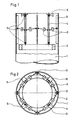
- Fig. 1 einen senkrechten Schnitt durch einen auf der Innenseite eines Antennenträgers angebrachten dynamischen Schwingungsdämpfer gemäß Erfindung mit Pendelstangen,
- Fig. 2 die Draufsicht auf den Schwingungsdämpfer nach Fig. 1,
- Fig. 3 einen senkrechten Schnitt durch einen auf der Innenseite eines Antennenträgers angebrachten dynamischen Schwingungsdämpfer gemäß Erfindung mit Winkelhebeln,
- Fig. 4 eine Seitenansicht eines auf der Außenseite eines Kamins angebrachten dynamischen Schwingungsdämpfers gemäß Erfindung mit Pendelstangen,
- Fig. 5 ein federndes und schwingungsdämpfendes Reibungsfeder-Element als Einzelteil im Längsschnitt.
- 1 is a vertical section through a dynamic vibration damper attached to the inside of an antenna carrier according to the invention with pendulum rods,
- 2 shows the top view of the vibration damper according to FIG. 1,
- 3 shows a vertical section through a dynamic vibration damper attached to the inside of an antenna carrier according to the invention with angle levers,
- 4 is a side view of a dynamic vibration damper attached to the outside of a fireplace according to the invention with pendulum rods,
- Fig. 5 is a resilient and vibration-damping friction spring element as a single part in longitudinal section.
Wie in Fig. 1 und 4 dargestellt, können die erfindungsgemäßen dynamischen Schwingungsdämpfer innen oder außen an einem Bauwerk 1, z.B. Antennenträger, Kamin oder Mast, angebracht werden.As shown in Figs. 1 and 4, the dynamic vibration dampers according to the invention can be inside or outside of a building 1, e.g. Antenna support, chimney or mast can be attached.
Am Bauwerk 1 sind diametral gegenüberliegend Konsolen 6 befestigt, an denen Pendelstangen 4 bzw. Winkelhebel 4a angelenkt sind. Diese Pendelstangen 4 bzw. Winkelhebel 4a nehmen das Gewicht der Dämpfermasse 2 auf, welche z.B. die Form eines geschlossenen oder offenen Kreisringes oder mehreckigen Ringes haben kann. Zwischen den Pendelstangen 4 bzw. den Winkelhebeln 4a und dem Bauwerk 1 sind sowohl federnde als auch dämpfende Reibungsfeder-Elemente 3 angeordnet. Diese Elemente 3 können an beliebigen Stellen der Pendelstangen 4 bzw. derWinkelhebel 4a und bauwerkseitig befestigten Anlenkleisten 5 angreifen. Sie werden durch geeignete gelenkige Verbindungen 7, z.B. Kugelgelenke mit Gabelkopf und Bolzen, an die Pendelstangen 4 bzw. die Winkelhebel 4a und die Anlenkleisten 5 angebunden.
Die Reibungsfeder-Elemente 3 haben wegen der Reibung in ihren Ringelementen eine Dämpfung und aufgrund der Zusammensetzung (Art, Anzahl) und der Vorspannung eine einstellbare, genau bestimmbare Federkennlinie. Vorteilhaft ist weiter, daß die sowohl federnden als auch dämpfenden Eigenschaften des Reibungsfeder-Elements 3 unabhängig von Schwinggeschwindigkeit, Schwingfrequenz und Temperatur sind. Die Elemente 3 sind überdies korrosionsbeständig und praktisch wartungsfrei. Durch die Form der Anordnung nehmen sie wenig Platz in Anspruch. Durch die sehr variable Anordnung der Reibungsfeder-Elemente 3 kann eine Dämpferausführung auf eine beliebige Eigenfrequenz, im Rahmen der vorgegebenen Geometrie, abgestimmt werden, d.h., es ist zu jeder Zeit eine Veränderung der Dämpfereigenfrequenz möglich.The
Gemäß Fig. 5 ist das Reibungsfeder-Element 3 im wesentlichen aus Außenringen 3a und axial geschlitzten Innenringen 3b gebildet, die über konische Berührungsflächen zusammenwirken und innerhalb eines Gehäuses 3c, 3d angeordnet sind. Das Gehäuse hat an den Enden seiner beiden, teleskopartig ineinander geführten Gehäuseteile 3c und 3d jeweils ein Befestigungsauge 3e. Zum Einstellen der Vorspannung des Reibungsfeder-Elements 3 dient eine zentrale Schraube 3f. Das Reibungsfeder-Element 3 ist im übrigen durch geeignete Anlenkung in Zug- und Druckrichtung beanspruchbar.5, the
Eine nicht dargestellte Abwandlung, beispielsweise der Fig. 1 und 2, kann darin bestehen, einige Reibungsfeder-Elemente 3 durch gelenkig angeordnete, starre Verbindungsteile zu ersetzen. Abweichend von den gezeigten Ausführungsbeispielen ist es auch durchaus möglich, Reibungsfeder-Elemente 3 radial zwischen dem Bauwerk 1 und der Dämpfermasse 2 anzuordnen. Ebenso vorstellbar sind Kombinationen von radialen, tangentialen und senkrechten Anordnungen von Reibungsfeder-Elementen 3; beispielsweise können ergänzend zu den in Fig. 1 und 2 tangential liegenden Reibungsfeder-Elementen 3 oder zu den gemäß Fig. 3 senkrecht stehenden Reibungsfeder-Elementen 3 auch Reibungsfeder-Elemente 3 radial angeordnet sein.A modification, not shown, for example FIGS. 1 and 2, may consist in replacing some
Claims (6)
Applications Claiming Priority (2)
| Application Number | Priority Date | Filing Date | Title |
|---|---|---|---|
| DE3823206 | 1988-07-08 | ||
| DE3823206A DE3823206A1 (en) | 1988-07-08 | 1988-07-08 | ARRANGEMENT FOR DAMPING VIBRATIONS ON CONSTRUCTIONS OR COMPONENTS |
Publications (2)
| Publication Number | Publication Date |
|---|---|
| EP0349979A1 true EP0349979A1 (en) | 1990-01-10 |
| EP0349979B1 EP0349979B1 (en) | 1991-10-23 |
Family
ID=6358280
Family Applications (1)
| Application Number | Title | Priority Date | Filing Date |
|---|---|---|---|
| EP89112197A Expired - Lifetime EP0349979B1 (en) | 1988-07-08 | 1989-07-04 | Arrangement for damping vibrations of structures or parts thereof |
Country Status (2)
| Country | Link |
|---|---|
| EP (1) | EP0349979B1 (en) |
| DE (2) | DE3823206A1 (en) |
Cited By (5)
| Publication number | Priority date | Publication date | Assignee | Title |
|---|---|---|---|---|
| DE4305132C1 (en) * | 1993-02-19 | 1994-04-21 | Uwe E Dr Dorka | Friction damper for securing support structure against dynamic effects - has superimposed friction plates contacting surfaces which are connected to friction damper connections |
| FR2698896A1 (en) * | 1992-12-09 | 1994-06-10 | Oudin Gilles | Device to prevent oscillation of tall structures - has inert mass attached to structure by elastic components and shock-absorbing cable springs which can be regulated |
| EP0543228B2 (en) † | 1991-11-18 | 2003-07-09 | Bayer Ag | Aqueous binder combination and its use |
| AT510170A4 (en) * | 2010-11-10 | 2012-02-15 | Penz Alois | TURMY, HOLY CONSTRUCTION, IN PARTICULAR WINCHING KAMIN |
| US20200284240A1 (en) * | 2017-08-08 | 2020-09-10 | Fm Energie Gmbh & Co. Kg | Rotation dampers and vibration absorbers equipped therewith |
Families Citing this family (6)
| Publication number | Priority date | Publication date | Assignee | Title |
|---|---|---|---|---|
| DE4009893A1 (en) * | 1990-03-28 | 1991-10-02 | Dietrich Fette | Vibration damper for chimney - is suspended pendulum-fashion with movements restricted by retainers connected to structure |
| DE4231729C2 (en) * | 1992-09-22 | 1995-09-28 | Selkirk Schornsteintechnik Gmb | Device for damping vibrations on free-standing structures |
| DE4231725C2 (en) * | 1992-09-22 | 1995-11-09 | Selkirk Schornsteintechnik Gmb | Device for damping vibrations on free-standing structures |
| US5819484A (en) * | 1995-07-28 | 1998-10-13 | Kar; Ramapada | Building structure with friction based supplementary damping in its bracing system for dissipating seismic energy |
| DE102007024431A1 (en) | 2007-05-25 | 2008-11-27 | Dr. Ing. H.C. F. Porsche Aktiengesellschaft | Device for damping vibrations in vibrating device, particularly in servo-hydraulic testing device such as hydro-pulser, has damper mass, which is charged with vibrations of vibrating device by receiving console |
| CN106812227A (en) * | 2017-03-23 | 2017-06-09 | 南通市苏东钢结构有限公司 | One kind classification is every damper |
Citations (3)
| Publication number | Priority date | Publication date | Assignee | Title |
|---|---|---|---|---|
| DE2551471A1 (en) * | 1975-11-15 | 1977-10-06 | Maurer Friedrich Soehne | Oscillation damper for slender chimney structures - has hinged telescopic attenuating elements fitted above annular oscillation unit |
| DE2806757A1 (en) * | 1978-02-17 | 1979-08-23 | Ka Be Werk Lufttechnik Und Ent | Dynamic oscillation modulator for chimney or pylon - has resiliently applied auxiliary mass combined with resilient damping elements |
| GB2040429A (en) * | 1979-01-17 | 1980-08-28 | Nat Res Dev | Improvements in or relating to stabilising structures against oscillation |
Family Cites Families (1)
| Publication number | Priority date | Publication date | Assignee | Title |
|---|---|---|---|---|
| NL287625A (en) * | 1962-05-23 |
-
1988
- 1988-07-08 DE DE3823206A patent/DE3823206A1/en not_active Withdrawn
-
1989
- 1989-07-04 EP EP89112197A patent/EP0349979B1/en not_active Expired - Lifetime
- 1989-07-04 DE DE8989112197T patent/DE58900398D1/en not_active Expired - Lifetime
Patent Citations (3)
| Publication number | Priority date | Publication date | Assignee | Title |
|---|---|---|---|---|
| DE2551471A1 (en) * | 1975-11-15 | 1977-10-06 | Maurer Friedrich Soehne | Oscillation damper for slender chimney structures - has hinged telescopic attenuating elements fitted above annular oscillation unit |
| DE2806757A1 (en) * | 1978-02-17 | 1979-08-23 | Ka Be Werk Lufttechnik Und Ent | Dynamic oscillation modulator for chimney or pylon - has resiliently applied auxiliary mass combined with resilient damping elements |
| GB2040429A (en) * | 1979-01-17 | 1980-08-28 | Nat Res Dev | Improvements in or relating to stabilising structures against oscillation |
Non-Patent Citations (1)
| Title |
|---|
| PATENT ABSTRACTS OF JAPAN, Band 8, Nr. 210 (M-328)[1647], 26. September 1984; & JP-A-59 97 342 (NIPPON KOKAN K.K.) 05-06-1984 * |
Cited By (8)
| Publication number | Priority date | Publication date | Assignee | Title |
|---|---|---|---|---|
| EP0543228B2 (en) † | 1991-11-18 | 2003-07-09 | Bayer Ag | Aqueous binder combination and its use |
| FR2698896A1 (en) * | 1992-12-09 | 1994-06-10 | Oudin Gilles | Device to prevent oscillation of tall structures - has inert mass attached to structure by elastic components and shock-absorbing cable springs which can be regulated |
| DE4305132C1 (en) * | 1993-02-19 | 1994-04-21 | Uwe E Dr Dorka | Friction damper for securing support structure against dynamic effects - has superimposed friction plates contacting surfaces which are connected to friction damper connections |
| AT510170A4 (en) * | 2010-11-10 | 2012-02-15 | Penz Alois | TURMY, HOLY CONSTRUCTION, IN PARTICULAR WINCHING KAMIN |
| AT510170B1 (en) * | 2010-11-10 | 2012-02-15 | Penz Alois | TURMY, HOLY CONSTRUCTION, IN PARTICULAR WINCHING KAMIN |
| WO2012061859A3 (en) * | 2010-11-10 | 2012-07-12 | Alois Penz | Tower-type, hollow structure, especially solar updraft chimney |
| US20200284240A1 (en) * | 2017-08-08 | 2020-09-10 | Fm Energie Gmbh & Co. Kg | Rotation dampers and vibration absorbers equipped therewith |
| US11603821B2 (en) * | 2017-08-08 | 2023-03-14 | Fm Energie Gmbh & Co. Kg | Rotation damper and vibration absorber equipped therewith |
Also Published As
| Publication number | Publication date |
|---|---|
| DE3823206A1 (en) | 1990-01-11 |
| EP0349979B1 (en) | 1991-10-23 |
| DE58900398D1 (en) | 1991-11-28 |
Similar Documents
| Publication | Publication Date | Title |
|---|---|---|
| DE69631871T2 (en) | Vibration damper for helicopter rotor system | |
| DE69925601T2 (en) | WIND TURBINE WING WITH U-SHAPED VIBRATION DAMPER | |
| DE2760119C2 (en) | Vibration isolation device | |
| EP2673531B1 (en) | Mounting an object on a structure in a vibration-free manner | |
| EP0349979B1 (en) | Arrangement for damping vibrations of structures or parts thereof | |
| DE3537573C2 (en) | ||
| EP3610172A1 (en) | Vibration damping of a wind turbine tower | |
| AT516245B1 (en) | Substructure to increase the seismic safety of a high-voltage component | |
| DE2806757C3 (en) | Arrangement for damping vibrations on buildings | |
| DE3113268A1 (en) | Vibration absorber | |
| DE102010038782A1 (en) | Torsional vibration damper with two-armed pendulum | |
| EP3433509B1 (en) | Compact three-dimensional ellipsoidal tuned pendulum | |
| DE3827329A1 (en) | TORQUE SUPPORT FOR DRIVES DRIVING ON SHAFT PIN, IN PARTICULAR FOR CONVERTER TILT DRIVES | |
| DE19715714A1 (en) | Vibration damper element for bridges etc. | |
| DE3211089A1 (en) | Mounting of a line bushing | |
| DE3816033C2 (en) | ||
| DE3414706C2 (en) | ||
| DE3003042C2 (en) | Arrangement for damping wind vibrations on an overhead line | |
| DE1278581B (en) | Vibration damper for overhead lines | |
| DE4231729C2 (en) | Device for damping vibrations on free-standing structures | |
| DE3214181C1 (en) | Device for damping vibrations in structures and structural members | |
| DE19711846A1 (en) | Mechanical vibration damper, e.g. for helicopter engine vibration damping | |
| DE3243168C2 (en) | ||
| EP0240572A1 (en) | Earthquake prevention unit | |
| DE3935893A1 (en) | Method of damping dynamic profiles - with damping load characteristics controlled to counteract resonant frequencies |
Legal Events
| Date | Code | Title | Description |
|---|---|---|---|
| PUAI | Public reference made under article 153(3) epc to a published international application that has entered the european phase |
Free format text: ORIGINAL CODE: 0009012 |
|
| AK | Designated contracting states |
Kind code of ref document: A1 Designated state(s): CH DE FR GB IT LI NL |
|
| 17P | Request for examination filed |
Effective date: 19900122 |
|
| 17Q | First examination report despatched |
Effective date: 19901029 |
|
| GRAA | (expected) grant |
Free format text: ORIGINAL CODE: 0009210 |
|
| AK | Designated contracting states |
Kind code of ref document: B1 Designated state(s): CH DE FR GB IT LI NL |
|
| ET | Fr: translation filed | ||
| REF | Corresponds to: |
Ref document number: 58900398 Country of ref document: DE Date of ref document: 19911128 |
|
| GBT | Gb: translation of ep patent filed (gb section 77(6)(a)/1977) | ||
| ITF | It: translation for a ep patent filed |
Owner name: SOCIETA' ITALIANA BREVETTI S.P.A. |
|
| PLBE | No opposition filed within time limit |
Free format text: ORIGINAL CODE: 0009261 |
|
| STAA | Information on the status of an ep patent application or granted ep patent |
Free format text: STATUS: NO OPPOSITION FILED WITHIN TIME LIMIT |
|
| 26N | No opposition filed | ||
| REG | Reference to a national code |
Ref country code: GB Ref legal event code: IF02 |
|
| PGFP | Annual fee paid to national office [announced via postgrant information from national office to epo] |
Ref country code: FR Payment date: 20020610 Year of fee payment: 14 |
|
| PGFP | Annual fee paid to national office [announced via postgrant information from national office to epo] |
Ref country code: GB Payment date: 20020612 Year of fee payment: 14 |
|
| PGFP | Annual fee paid to national office [announced via postgrant information from national office to epo] |
Ref country code: CH Payment date: 20020617 Year of fee payment: 14 |
|
| PGFP | Annual fee paid to national office [announced via postgrant information from national office to epo] |
Ref country code: NL Payment date: 20020619 Year of fee payment: 14 Ref country code: DE Payment date: 20020619 Year of fee payment: 14 |
|
| PG25 | Lapsed in a contracting state [announced via postgrant information from national office to epo] |
Ref country code: GB Free format text: LAPSE BECAUSE OF NON-PAYMENT OF DUE FEES Effective date: 20030704 |
|
| PG25 | Lapsed in a contracting state [announced via postgrant information from national office to epo] |
Ref country code: LI Free format text: LAPSE BECAUSE OF NON-PAYMENT OF DUE FEES Effective date: 20030731 Ref country code: CH Free format text: LAPSE BECAUSE OF NON-PAYMENT OF DUE FEES Effective date: 20030731 |
|
| PG25 | Lapsed in a contracting state [announced via postgrant information from national office to epo] |
Ref country code: NL Free format text: LAPSE BECAUSE OF NON-PAYMENT OF DUE FEES Effective date: 20040201 |
|
| PG25 | Lapsed in a contracting state [announced via postgrant information from national office to epo] |
Ref country code: DE Free format text: LAPSE BECAUSE OF NON-PAYMENT OF DUE FEES Effective date: 20040203 |
|
| GBPC | Gb: european patent ceased through non-payment of renewal fee |
Effective date: 20030704 |
|
| REG | Reference to a national code |
Ref country code: CH Ref legal event code: PL |
|
| PG25 | Lapsed in a contracting state [announced via postgrant information from national office to epo] |
Ref country code: FR Free format text: LAPSE BECAUSE OF NON-PAYMENT OF DUE FEES Effective date: 20040331 |
|
| NLV4 | Nl: lapsed or anulled due to non-payment of the annual fee |
Effective date: 20040201 |
|
| REG | Reference to a national code |
Ref country code: FR Ref legal event code: ST |
|
| PG25 | Lapsed in a contracting state [announced via postgrant information from national office to epo] |
Ref country code: IT Free format text: LAPSE BECAUSE OF NON-PAYMENT OF DUE FEES;WARNING: LAPSES OF ITALIAN PATENTS WITH EFFECTIVE DATE BEFORE 2007 MAY HAVE OCCURRED AT ANY TIME BEFORE 2007. THE CORRECT EFFECTIVE DATE MAY BE DIFFERENT FROM THE ONE RECORDED. Effective date: 20050704 |