EP0349801A2 - Dynamoelektrische Maschine mit einem Schirm für den diamagnetischen Fluss - Google Patents
Dynamoelektrische Maschine mit einem Schirm für den diamagnetischen Fluss Download PDFInfo
- Publication number
- EP0349801A2 EP0349801A2 EP89110869A EP89110869A EP0349801A2 EP 0349801 A2 EP0349801 A2 EP 0349801A2 EP 89110869 A EP89110869 A EP 89110869A EP 89110869 A EP89110869 A EP 89110869A EP 0349801 A2 EP0349801 A2 EP 0349801A2
- Authority
- EP
- European Patent Office
- Prior art keywords
- stator
- flux shield
- machine
- winding
- flux
- Prior art date
- Legal status (The legal status is an assumption and is not a legal conclusion. Google has not performed a legal analysis and makes no representation as to the accuracy of the status listed.)
- Withdrawn
Links
Images


Classifications
-
- H—ELECTRICITY
- H02—GENERATION; CONVERSION OR DISTRIBUTION OF ELECTRIC POWER
- H02K—DYNAMO-ELECTRIC MACHINES
- H02K55/00—Dynamo-electric machines having windings operating at cryogenic temperatures
- H02K55/02—Dynamo-electric machines having windings operating at cryogenic temperatures of the synchronous type
-
- H—ELECTRICITY
- H02—GENERATION; CONVERSION OR DISTRIBUTION OF ELECTRIC POWER
- H02K—DYNAMO-ELECTRIC MACHINES
- H02K11/00—Structural association of dynamo-electric machines with electric components or with devices for shielding, monitoring or protection
-
- H—ELECTRICITY
- H02—GENERATION; CONVERSION OR DISTRIBUTION OF ELECTRIC POWER
- H02K—DYNAMO-ELECTRIC MACHINES
- H02K11/00—Structural association of dynamo-electric machines with electric components or with devices for shielding, monitoring or protection
- H02K11/01—Structural association of dynamo-electric machines with electric components or with devices for shielding, monitoring or protection for shielding from electromagnetic fields, i.e. structural association with shields
- H02K11/014—Shields associated with stationary parts, e.g. stator cores
-
- H—ELECTRICITY
- H02—GENERATION; CONVERSION OR DISTRIBUTION OF ELECTRIC POWER
- H02K—DYNAMO-ELECTRIC MACHINES
- H02K3/00—Details of windings
- H02K3/46—Fastening of windings on the stator or rotor structure
- H02K3/47—Air-gap windings, i.e. iron-free windings
-
- H—ELECTRICITY
- H02—GENERATION; CONVERSION OR DISTRIBUTION OF ELECTRIC POWER
- H02K—DYNAMO-ELECTRIC MACHINES
- H02K9/00—Arrangements for cooling or ventilating
- H02K9/19—Arrangements for cooling or ventilating for machines with closed casing and closed-circuit cooling using a liquid cooling medium, e.g. oil
- H02K9/197—Arrangements for cooling or ventilating for machines with closed casing and closed-circuit cooling using a liquid cooling medium, e.g. oil in which the rotor or stator space is fluid-tight, e.g. to provide for different cooling media for rotor and stator
-
- H—ELECTRICITY
- H02—GENERATION; CONVERSION OR DISTRIBUTION OF ELECTRIC POWER
- H02K—DYNAMO-ELECTRIC MACHINES
- H02K1/00—Details of the magnetic circuit
- H02K1/02—Details of the magnetic circuit characterised by the magnetic material
-
- H—ELECTRICITY
- H02—GENERATION; CONVERSION OR DISTRIBUTION OF ELECTRIC POWER
- H02K—DYNAMO-ELECTRIC MACHINES
- H02K1/00—Details of the magnetic circuit
- H02K1/06—Details of the magnetic circuit characterised by the shape, form or construction
- H02K1/12—Stationary parts of the magnetic circuit
-
- Y—GENERAL TAGGING OF NEW TECHNOLOGICAL DEVELOPMENTS; GENERAL TAGGING OF CROSS-SECTIONAL TECHNOLOGIES SPANNING OVER SEVERAL SECTIONS OF THE IPC; TECHNICAL SUBJECTS COVERED BY FORMER USPC CROSS-REFERENCE ART COLLECTIONS [XRACs] AND DIGESTS
- Y02—TECHNOLOGIES OR APPLICATIONS FOR MITIGATION OR ADAPTATION AGAINST CLIMATE CHANGE
- Y02E—REDUCTION OF GREENHOUSE GAS [GHG] EMISSIONS, RELATED TO ENERGY GENERATION, TRANSMISSION OR DISTRIBUTION
- Y02E40/00—Technologies for an efficient electrical power generation, transmission or distribution
- Y02E40/60—Superconducting electric elements or equipment; Power systems integrating superconducting elements or equipment
-
- Y—GENERAL TAGGING OF NEW TECHNOLOGICAL DEVELOPMENTS; GENERAL TAGGING OF CROSS-SECTIONAL TECHNOLOGIES SPANNING OVER SEVERAL SECTIONS OF THE IPC; TECHNICAL SUBJECTS COVERED BY FORMER USPC CROSS-REFERENCE ART COLLECTIONS [XRACs] AND DIGESTS
- Y10—TECHNICAL SUBJECTS COVERED BY FORMER USPC
- Y10S—TECHNICAL SUBJECTS COVERED BY FORMER USPC CROSS-REFERENCE ART COLLECTIONS [XRACs] AND DIGESTS
- Y10S505/00—Superconductor technology: apparatus, material, process
- Y10S505/70—High TC, above 30 k, superconducting device, article, or structured stock
- Y10S505/701—Coated or thin film device, i.e. active or passive
-
- Y—GENERAL TAGGING OF NEW TECHNOLOGICAL DEVELOPMENTS; GENERAL TAGGING OF CROSS-SECTIONAL TECHNOLOGIES SPANNING OVER SEVERAL SECTIONS OF THE IPC; TECHNICAL SUBJECTS COVERED BY FORMER USPC CROSS-REFERENCE ART COLLECTIONS [XRACs] AND DIGESTS
- Y10—TECHNICAL SUBJECTS COVERED BY FORMER USPC
- Y10S—TECHNICAL SUBJECTS COVERED BY FORMER USPC CROSS-REFERENCE ART COLLECTIONS [XRACs] AND DIGESTS
- Y10S505/00—Superconductor technology: apparatus, material, process
- Y10S505/825—Apparatus per se, device per se, or process of making or operating same
- Y10S505/876—Electrical generator or motor structure
- Y10S505/877—Rotary dynamoelectric type
- Y10S505/878—Rotary dynamoelectric type with cooling
Definitions
- the present invention relates generally to the construction and configuration of electrical machines including motors and generators. More specifically, the invention relates to an AC electrical machine featuring increased efficiency and reduced size as a result of the elimination of iron core losses and winding losses by the strategic use of superconducting diamagnetic materials.
- stator windings were themselves surrounded by a stator core.
- the stator core usually included teeth extending radially inward defining slots into which the stator windings would be placed.
- the air gap for these types of machines is defined as the distance between the surface of the rotor magnetic pole and the innermost portion of the stator core.
- the stator core provided a magnetic link between opposite magnetic poles on the rotor, with the only open sections of the magnetic link being those defined by the air gap. While the stator core and stator teeth were believed necessary to provide the magnetic link within electrical machines, the core is also a source of energy loss within the machine primarily in the form of hysteresis and eddy current losses.
- the invention completely eliminates the ferromagnetic stator core, replacing the core with a diamagnetic superconducting flux shield.
- the diamagnetic property of the flux shield prevents magnetic flux penetration, effectively bottling the magnetic field produced by a permanent magnet rotor.
- the magnetic field is thus confined within a cylinder defined by the outer diameter of the rotor and the inner diameter of the flux shield.
- the machine's stator windings are also disposed within this cylinder, mounted within slots defined by non-metallic fins which project radially outward from a non-metallic cylinder having an internal diameter slightly larger than the outer diameter of the rotor. It may therefore be appreciated that the magnetic field is constrained to rotate synchronously with the rotor within a cylindrical area substantially filled with stator windings. Thereby, the entire magnetic field is available to induce electrical potential within the stator windings.
- a further object of the invention is an electrical machine wherein the machine rotor tends to center itself within the diamagnetic flux shield cylinder by virtue of the interaction of the rotor magnets, the diamagnetic flux shield and the magnetic field surrounding the rotor and compressed within the flux shield.
- the rotor acts as a magnetic bearing, centralizing and stabilizing itself within the electrical machine. This significantly reduces frictional losses associated with the shaft bearings, and the machine may not require journal bearings for the rotor assembly.
- a further object of the invention contemplates the use of superconducting wires for the stator windings.
- Superconducting wires eliminate resistance losses within the stator windings, thereby potentially increasing the machine efficiency. Additionally, the development of new superconducting material which remain superconductive at higher temperatures and which can transmit higher current densities will allow the number of stator windings to be reduced and the area dedicated to stator windings within the electrical machine to be compressed.
- Fig. 1 depicts a cutaway view of a dynamoelectric machine 10 of the present invention
- Fig. 2 shows a cross-sectional view of the machine 10 along the line 2-2 of Fig. 1.
- the machine 10 includes a housing assembly 12 which contains therein a stator assembly 14 and a rotor assembly 16.
- the housing assembly 12 is made up of three parts, a generally cylindrical central housing section 18, and first and second end bells 20, 22 respectively, which are attached to opposite ends of central housing section 18.
- the central housing section 18 additionally has a coolant inlet port 24 located near one end and a coolant outlet port 26 located near an opposite end.
- the ends bells 20, each have cylindrical bearing support areas 28, 30 which project axially a short distance toward the center of the machine 10.
- the stator assembly 14 includes a cylindrical winding support structure 32 having a plurality of radially outwardly extending, axially aligned support fins 34 which define a plurality of winding slots 36 therebetween.
- the winding support structure 32 is adapted so as to be mounted over portions of the cylindrical bearing support areas 28 and 30 of end bells 20, 22.
- the housing assembly 12 and the winding support structure 32 combine to define a generally cylindrically shaped pressure cavity 38 wherein the stator assembly 14 is located.
- the stator assembly 14 further includes a plurality of stator windings 40, which are adapted to have sections thereof placed within the winding slots 36 of winding support structure 32.
- Stator assembly 14 also includes a cylindrical diamagnetic flux shield 42, formed for example from metal oxide based ceramic superconducting compounds such as Y Ba2 Cu3 O 7-x , which is mounted about the outer periphery of the support fins 34 of winding support structure 32, and separated from the stator windings 40 by a non-magnetic spacer 44.
- a cylindrical diamagnetic flux shield 42 formed for example from metal oxide based ceramic superconducting compounds such as Y Ba2 Cu3 O 7-x , which is mounted about the outer periphery of the support fins 34 of winding support structure 32, and separated from the stator windings 40 by a non-magnetic spacer 44.
- the rotor assembly 16 is mounted internally to the stator assembly 14, and is depicted as including a cylindrical two pole permanent magnet 46 contained within a cylindrical retaining sleeve 48 and having a first end piece 50 and a second end price 52 fixedly attached to the ends of the cylindrical retaining sleeve 48.
- Projecting from the first end piece 50 is a power coupling shaft 54, while a support shaft 56 projects from the second end piece 52.
- Power coupling shaft 54 projects through the cylindrical bearing support area 28 of first end bell 20 and is axially supported by bearing 58 mounted therewithin.
- Support shaft 56 similarly projects into the cylindrical bearing support area 30 of the second end bell 22 and is axially supported by bearing 60 mounted therewithin.
- Thrust bearings 62 and 64 may be required to be located between the end pieces 50, 52 of rotor assembly 16 and bearing support areas 28, 30 of end bells 20, 22.
- the rotor assembly may also include diamagnetic end flux shield disks 66 and 68 located adjacent to the ends of the permanent magnet 46 to focus the flux and to prevent magnet flux leakage at the ends of the magnet.
- the support fins 38 are configured so as to extend along the winding support structure 36 only for the length of the permanent magnet 22 of rotor assembly 20, while the cylindrical portion of winding support structure 36 is approximately as long as the central housing section 18.
- inlet manifold 70 and outlet manifold 72 At each end of the machine 10, there are defined toroidal cavities identified as inlet manifold 70 and outlet manifold 72.
- inlet manifold 70 and 72 Within the manifolds 70 and 72 are located the end turn sections of stator windings 40.
- An aperture 74 within the central housing section 18 is used to bring winding leads 76 into the machine 10, which aperture 74 is sealed to prevent coolant leaks.
- the coolant inlet port 24 is configured to delivery cooling fluid into the inlet manifold 20 wherein the fluid is distributed around the circumference of the machine in intimate contact with the stator windings 40.
- the cooling fluid flows axially through the winding slots 36, cooling the stator windings 40 as well as the flux shield 42. Upon exiting the winding slots 36, the cooling fluid flows into outlet manifold 72 and is allowed to escape through coolant outlet port 26. This arrangement is ideal for providing coolant flow to the stator windings 40 and flux shield 42.
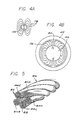
- Fig. 4 A and B shows schematic views of a cross-section of the cylindrical permanent magnet 46 which is diametrically magnetized, the magnetic field represented by magnetic lines of force 78 produced by the magnet, and the bottling effect that the flux shield 42 has on the magnetic field.
- Fig. 4A depicts the magnetic field which surrounds a cylindrical permanent magnet as it would exist in free space.
- the magnetic lines of force 78 prescribe generally eliptical paths of increasing size.
- Fig. 4B depicts the effect that the magnetic flux shield 42 has on the magnetic field surrounding the permanent magnet 46.
- the diamagnetic property of the flux shield 42 does not allow for penetration of the magnetic flux and thus the flux shield compresses the magnetic field surrounding the magnet 46 into the cylindrical space 76 between the inner diameter of flux shield 42 and the outer diameter of permanent magnet 46.
- the permanent magnet 46 is caused to rotate with the rotor assembly 16 of Fig. 1, the magnetic field will also rotate within the cylindrical space 80 resulting in a time varying magnetic field at any given point therein.
- the stator windings 40 are placed within the cylindrical space 80, they will be subjected to the time varying magnetic field.
- stator windings 40 When the dynamoelectric machine 10 is operating as a generator, mechanical shaft power is provided via power coupling shaft 54 to cause the rotor assembly 16 to rotate. The two pole permanent magnet 46 and its surrounding magnetic field thus also rotate producing a potential in stator windings 40 which may be connected to a power consuming device (not shown) external to the machine 10. Conversely, when the machine 10 is operating as a motor, current is supplied sequentially to stator windings 40 which themselves then produce a magnetic field to react with the magnetic field of rotor assembly 16 to drive the rotor assembly 16 and yield a mechanical output via power coupling shaft 54.
- the rotor assembly 16 may include the pair of flux shield disks 66, 68 located proximate to the ends of the permanent magnet 46 and inside of end pieces 50 and 52. These flux shield disks 66, 68 are formed of a superconductive, diamagnetic material such as those compounds identified generally by the formula Y Ba2 Cu3 O 7-x.
- the stator windings 40 of the machine 10 will be required to carry relatively high current densities within a high magnetic flux environment.
- the Litz configuration as shown in Fig. 5 includes a number of individual thin strands of wire 82 equally divided into five cables 84, which five cables are wound together so as to create a bundled cable 86 having an opening 88 within the center for coolant fluid flow. It is important to note that within the Litz configuration each individual strand traverses all possible distances from the rotor assembly somewhere along its length within the winding slot. This prevents recirculating currents when all of the individual strands are connected at the output.
- wires made from metal oxide and ceramic superconducting compounds such as Y Ba2 Cu3 O 7-x may also be used within the dynamoelectric machine 10.
- superconducting wires it may be appreciated that the diamagnetic property of the material will not allow magnetic flux penetration. Thus, the mangetic flux will be forced to go around the field windings 40 and will effectively progress radially outward along the support fins 34.
- the magnetic flux Upon reaching the proximity of the flux shield 42, the magnetic flux will turn and be concentrated close to the interior wall of flux shield 42 until reaching the opposite magnetic pole of the permanent magnet at which time the flux will turn and progress radially inwardly along another support fin 34, thus completing the magnetic path and providing the necessary linking of stator windings 40.
Landscapes
- Engineering & Computer Science (AREA)
- Power Engineering (AREA)
- Physics & Mathematics (AREA)
- Electromagnetism (AREA)
- Superconductive Dynamoelectric Machines (AREA)
- Motor Or Generator Frames (AREA)
Applications Claiming Priority (2)
| Application Number | Priority Date | Filing Date | Title |
|---|---|---|---|
| US07/217,729 US4908347A (en) | 1985-11-20 | 1988-07-07 | Dynamoelectric machine with diamagnetic flux shield |
| US217729 | 1988-07-07 |
Publications (2)
| Publication Number | Publication Date |
|---|---|
| EP0349801A2 true EP0349801A2 (de) | 1990-01-10 |
| EP0349801A3 EP0349801A3 (de) | 1990-06-20 |
Family
ID=22812262
Family Applications (1)
| Application Number | Title | Priority Date | Filing Date |
|---|---|---|---|
| EP89110869A Withdrawn EP0349801A3 (de) | 1988-07-07 | 1989-06-15 | Dynamoelektrische Maschine mit einem Schirm für den diamagnetischen Fluss |
Country Status (2)
| Country | Link |
|---|---|
| US (1) | US4908347A (de) |
| EP (1) | EP0349801A3 (de) |
Cited By (5)
| Publication number | Priority date | Publication date | Assignee | Title |
|---|---|---|---|---|
| WO1992010024A1 (en) * | 1990-11-30 | 1992-06-11 | Kinetron B.V. | Miniature motor |
| EP0495681A3 (de) * | 1991-01-17 | 1994-04-27 | Yoshihiro Ohnishi | |
| GB2324913A (en) * | 1997-04-02 | 1998-11-04 | Aisin Seiki | Magnetic shielding in high speed turbo alternator/motor |
| WO2003021101A1 (en) * | 2001-09-06 | 2003-03-13 | Iouri Baikov | Design of device for the processing of liquid and gaseous fuel, device for the reduction of friction between moving parts, device for the processing of radioactive materials, device for the reduction of power loss in an electric machine and device for biological object stimulation |
| WO2009068844A1 (en) * | 2007-11-27 | 2009-06-04 | Rolls-Royce Plc | A superconducting electrical machine |
Families Citing this family (57)
| Publication number | Priority date | Publication date | Assignee | Title |
|---|---|---|---|---|
| JPH04145863A (ja) * | 1990-10-05 | 1992-05-19 | Toshiba Corp | 超電導回転電機 |
| US5159219A (en) * | 1991-05-16 | 1992-10-27 | University Of Houston-University Park | Opposed-magnet bearing with interposed superconductor |
| GB9112059D0 (en) * | 1991-06-05 | 1991-07-24 | Jestar Ltd | Electrical machines |
| US5256637A (en) * | 1991-07-22 | 1993-10-26 | Mechanical Technology Inc. | Superconducting coil bearings for rotor load |
| DE69208558T2 (de) * | 1991-08-06 | 1996-09-19 | Koyo Seiko Co | Lagervorrichtung |
| US5250861A (en) * | 1992-04-13 | 1993-10-05 | Cummins Stephen F | Superconductor electrical power generating system |
| JP2775209B2 (ja) * | 1992-04-17 | 1998-07-16 | セイコーインスツルメンツ株式会社 | 直流モータ |
| SE508318C2 (sv) * | 1993-05-26 | 1998-09-21 | Atlas Copco Tools Ab | Stator för en elektrisk maskin |
| US5455470A (en) * | 1994-03-17 | 1995-10-03 | Alliedsignal Inc. | Electrical machines and components thereof incorporating foil journal bearings |
| DE4414527C1 (de) * | 1994-04-26 | 1995-08-31 | Orto Holding Ag | Elektronisch kommutierte Gleichstrommaschine |
| US5841211A (en) * | 1994-07-15 | 1998-11-24 | Boyes; Thomas G. | Superconducting generator and system therefor |
| US5661353A (en) * | 1995-05-25 | 1997-08-26 | Allen-Bradley Company, Inc. | Electrostatic shield for AC motor |
| US5907205A (en) * | 1996-07-08 | 1999-05-25 | Herman; Robert Wayne | Constant reluctance rotating magnetic field devices with laminationless stator |
| US5873710A (en) * | 1997-01-27 | 1999-02-23 | Copeland Corporation | Motor spacer for hermetic motor-compressor |
| EP1369280B1 (de) * | 1997-09-12 | 2005-12-07 | Honda Giken Kogyo Kabushiki Kaisha | Antriebsvorrichtung für Hybridfahrzeug |
| AU1092799A (en) * | 1997-10-16 | 1999-05-03 | Steven L. Sullivan | Generators and transformers with toroidally wound stator winding |
| US6373921B1 (en) | 1999-12-27 | 2002-04-16 | General Electric Company | X-ray unit including electromagnetic shield |
| DE60135812D1 (de) * | 2000-07-17 | 2008-10-30 | Michelin Rech Tech | Stator einer drehenden elektrischen Maschine |
| US6787948B2 (en) * | 2001-06-29 | 2004-09-07 | Bae Systems Controls Inc. | Stator construction for high performance rotating machines |
| US20050260331A1 (en) * | 2002-01-22 | 2005-11-24 | Xingwu Wang | Process for coating a substrate |
| JP3758583B2 (ja) * | 2002-02-06 | 2006-03-22 | 日産自動車株式会社 | 回転体の冷却構造 |
| US7262537B2 (en) * | 2002-07-19 | 2007-08-28 | Hamilton Sundstrand Corporation | Electric motor and generator component having a plurality of windings made from a plurality of individually conductive wires |
| US6787949B2 (en) * | 2002-07-24 | 2004-09-07 | Emerson Electric Co. | Optimized thermal system for an electric motor |
| JP2004112849A (ja) * | 2002-09-13 | 2004-04-08 | Honda Motor Co Ltd | 永久磁石型回転子 |
| US20040104623A1 (en) * | 2002-11-28 | 2004-06-03 | Mn Engineering Co., Ltd. | Vibration operated generator |
| US20050261763A1 (en) * | 2003-04-08 | 2005-11-24 | Xingwu Wang | Medical device |
| US20050244337A1 (en) * | 2003-04-08 | 2005-11-03 | Xingwu Wang | Medical device with a marker |
| US20050278020A1 (en) * | 2003-04-08 | 2005-12-15 | Xingwu Wang | Medical device |
| US20050119725A1 (en) * | 2003-04-08 | 2005-06-02 | Xingwu Wang | Energetically controlled delivery of biologically active material from an implanted medical device |
| US20050240100A1 (en) * | 2003-04-08 | 2005-10-27 | Xingwu Wang | MRI imageable medical device |
| US20050155779A1 (en) * | 2003-04-08 | 2005-07-21 | Xingwu Wang | Coated substrate assembly |
| FR2857521B1 (fr) * | 2003-07-11 | 2005-09-23 | Thales Sa | Refroidisseur d'un stator |
| BE1015766A3 (de) * | 2003-11-05 | 2005-08-02 | Atlas Copco Airpower Nv | |
| US20070027532A1 (en) * | 2003-12-22 | 2007-02-01 | Xingwu Wang | Medical device |
| US20060043801A1 (en) * | 2004-08-27 | 2006-03-02 | Caterpillar Inc. | Liquid cooled switched reluctance electric machine |
| US20060118758A1 (en) * | 2004-09-15 | 2006-06-08 | Xingwu Wang | Material to enable magnetic resonance imaging of implantable medical devices |
| US8330316B2 (en) | 2011-03-09 | 2012-12-11 | Novatorque, Inc. | Rotor-stator structures including boost magnet structures for magnetic regions in rotor assemblies disposed external to boundaries of conically-shaped spaces |
| US20120228979A1 (en) * | 2011-03-09 | 2012-09-13 | Novatorque, Inc. | Outer rotor assemblies for electrodynamic machines |
| US7982350B2 (en) | 2004-10-25 | 2011-07-19 | Novatorque, Inc. | Conical magnets and rotor-stator structures for electrodynamic machines |
| US9093874B2 (en) | 2004-10-25 | 2015-07-28 | Novatorque, Inc. | Sculpted field pole members and methods of forming the same for electrodynamic machines |
| US8543365B1 (en) | 2004-10-25 | 2013-09-24 | Novatorque, Inc. | Computer-readable medium, a method and an apparatus for designing and simulating electrodynamic machines implementing conical and cylindrical magnets |
| US7876016B2 (en) * | 2007-11-15 | 2011-01-25 | Sundyne Corporation | Stator winding method and apparatus |
| EP2072826B1 (de) * | 2007-12-17 | 2015-10-14 | Grundfos Management A/S | Rotor für einem Spaltrohrmotor |
| FR2935561A1 (fr) * | 2008-09-03 | 2010-03-05 | Michelin Soc Tech | Flasque connecteur pour machine electrique a enroulements statoriques |
| FR2935563A1 (fr) * | 2008-09-03 | 2010-03-05 | Michelin Soc Tech | Construction de stator pour machine electrique |
| FR2935564A1 (fr) | 2008-09-03 | 2010-03-05 | Michelin Soc Tech | Dispositif de montage d'un resolver dans une machine electrique |
| AU2011209867B2 (en) * | 2010-01-27 | 2016-05-19 | Exxonmobil Upstream Research Company | Superconducting system for enhanced natural gas production |
| US9240270B2 (en) * | 2011-10-07 | 2016-01-19 | Utah State University | Wireless power transfer magnetic couplers |
| EP2597757B1 (de) * | 2011-11-24 | 2014-01-08 | Maxon Motor AG | Elektromotor für Hochtemperaturanwendungen |
| AU2015236298B2 (en) | 2014-03-24 | 2018-08-09 | Apple Inc. | Magnetic shielding in inductive power transfer |
| US9460846B2 (en) | 2014-06-20 | 2016-10-04 | Apple Inc. | Methods for forming shield materials onto inductive coils |
| CN104124846A (zh) * | 2014-08-13 | 2014-10-29 | 四川埃姆克伺服科技有限公司 | 一种永磁同步电机 |
| US10699842B2 (en) | 2014-09-02 | 2020-06-30 | Apple Inc. | Magnetically doped adhesive for enhancing magnetic coupling |
| US10327326B2 (en) | 2017-08-17 | 2019-06-18 | Apple Inc. | Electronic device with encapsulated circuit assembly having an integrated metal layer |
| CN108110915B (zh) * | 2018-01-25 | 2024-06-04 | 博远机电(嘉兴)有限公司 | 定子密封结构及电机 |
| DE102018121203A1 (de) * | 2018-08-30 | 2020-03-05 | Thyssenkrupp Ag | Kühlvorrichtung, Motorgehäuse und Motoreinheit |
| US20230378842A1 (en) * | 2020-09-21 | 2023-11-23 | Lg Innotek Co., Ltd. | Motor |
Family Cites Families (14)
| Publication number | Priority date | Publication date | Assignee | Title |
|---|---|---|---|---|
| US3564307A (en) * | 1968-07-24 | 1971-02-16 | Hitachi Ltd | Rotary electric ac generator utilizing the magnetic shielding and trapping by superconducting plates |
| US3742265A (en) * | 1972-05-25 | 1973-06-26 | Massachusetts Inst Technology | Superconducting apparatus with double armature structure |
| US3816780A (en) * | 1972-08-18 | 1974-06-11 | Massachusetts Inst Technology | Rotor structure for supercooled field winding |
| US4087711A (en) * | 1974-10-22 | 1978-05-02 | Massachusetts Institute Of Technology | Rotating electric machine having a toroidal-winding armature |
| US4031422A (en) * | 1975-09-02 | 1977-06-21 | General Electric Company | Gas cooled flux shield for dynamoelectric machine |
| US4076988A (en) * | 1976-08-17 | 1978-02-28 | Westinghouse Electric Corporation | Superconducting dynamoelectric machine having a liquid metal shield |
| SU873332A1 (ru) * | 1979-02-15 | 1981-10-15 | Предприятие П/Я Р-6794 | Статор криогенной электрической машины |
| DE3019673A1 (de) * | 1980-05-22 | 1981-11-26 | SIEMENS AG AAAAA, 1000 Berlin und 8000 München | Einrichtung zur kuehlung einer supraleitenden erregerwicklung und eines daemperschildes des laeufers einer elektrischen maschine |
| US4426592A (en) * | 1982-01-18 | 1984-01-17 | Berzin Evgeny K | Electrical machine with superconducting inductor and gas cooling of normal-conductivity windings |
| US4489267A (en) * | 1982-02-12 | 1984-12-18 | Black & Decker Inc. | Waveform synthesizer and motor controller |
| US4638194A (en) * | 1983-07-18 | 1987-01-20 | Keefe Peter D | Coherent magneto-caloric effect superconductive heat engine process cycle |
| US4583014A (en) * | 1984-09-26 | 1986-04-15 | Westinghouse Electric Corp. | Dynamoelectric machine with a rotor having a superconducting field winding and damper winding |
| US4709180A (en) * | 1985-11-20 | 1987-11-24 | The Garrett Corporation | Toothless stator construction for electrical machines |
| US4733118A (en) * | 1986-09-22 | 1988-03-22 | Hhk Inc. | Low damping torque brushless D.C. motor |
-
1988
- 1988-07-07 US US07/217,729 patent/US4908347A/en not_active Expired - Lifetime
-
1989
- 1989-06-15 EP EP89110869A patent/EP0349801A3/de not_active Withdrawn
Cited By (7)
| Publication number | Priority date | Publication date | Assignee | Title |
|---|---|---|---|---|
| WO1992010024A1 (en) * | 1990-11-30 | 1992-06-11 | Kinetron B.V. | Miniature motor |
| EP0495681A3 (de) * | 1991-01-17 | 1994-04-27 | Yoshihiro Ohnishi | |
| GB2324913A (en) * | 1997-04-02 | 1998-11-04 | Aisin Seiki | Magnetic shielding in high speed turbo alternator/motor |
| US5912516A (en) * | 1997-04-02 | 1999-06-15 | Aisin Seiki Kabushiki Kaisha | High speed alternator/motor |
| WO2003021101A1 (en) * | 2001-09-06 | 2003-03-13 | Iouri Baikov | Design of device for the processing of liquid and gaseous fuel, device for the reduction of friction between moving parts, device for the processing of radioactive materials, device for the reduction of power loss in an electric machine and device for biological object stimulation |
| WO2009068844A1 (en) * | 2007-11-27 | 2009-06-04 | Rolls-Royce Plc | A superconducting electrical machine |
| US8378537B2 (en) | 2007-11-27 | 2013-02-19 | Rolls-Royce Plc | Superconducting electrical machine |
Also Published As
| Publication number | Publication date |
|---|---|
| EP0349801A3 (de) | 1990-06-20 |
| US4908347A (en) | 1990-03-13 |
Similar Documents
| Publication | Publication Date | Title |
|---|---|---|
| US4908347A (en) | Dynamoelectric machine with diamagnetic flux shield | |
| US4709180A (en) | Toothless stator construction for electrical machines | |
| US4968911A (en) | Clam-shell stator construction for electrical machines | |
| US5304883A (en) | Ring wound stator having variable cross section conductors | |
| US4852245A (en) | Toothless stator electrical machine construction method | |
| US7915777B2 (en) | Ring coil motor | |
| US5030877A (en) | Turbine engine with integral clam shell dynamoelectric machine | |
| KR101530140B1 (ko) | 전기 기계용 고정자 및 전기 기계 | |
| KR101531728B1 (ko) | 코일이 독립적이고, 부품이 모듈형이며 자기베어링이 달린 전자기 기계 | |
| KR960003205B1 (ko) | 전자속 반전형 자기저항 가변장치 | |
| CA2316708C (en) | Cage-type induction motor for high rotational speeds | |
| WO1999019962B1 (en) | Generators and transformers with toroidally wound stator winding | |
| US20200350800A1 (en) | System and method for cooling an electric machine | |
| KR101104499B1 (ko) | 유도자형 동기기 | |
| US4987674A (en) | Method of making a dynamoelectric machine with superconducting magnet rotor | |
| WO1991001585A1 (en) | Toothless stator construction for electrical machines | |
| US6891308B2 (en) | Extended core for motor/generator | |
| FI20185259A1 (en) | Electric machine stator and electric machine | |
| US20130127267A1 (en) | Cylindrical linear motor with laminated stator | |
| EP1228558B1 (de) | Elektrische maschine mit statorwicklungen | |
| WO2022160514A1 (zh) | 无换向装置超导直流电机 | |
| US7291958B2 (en) | Rotating back iron for synchronous motors/generators | |
| RU2546970C1 (ru) | Униполярный генератор постоянного тока | |
| US5317227A (en) | Rotor with hollow cylindrical permanent magnet | |
| Hesmondhalgh et al. | Slotless construction for small synchronous motors using samarium cobalt magnets |
Legal Events
| Date | Code | Title | Description |
|---|---|---|---|
| PUAI | Public reference made under article 153(3) epc to a published international application that has entered the european phase |
Free format text: ORIGINAL CODE: 0009012 |
|
| AK | Designated contracting states |
Kind code of ref document: A2 Designated state(s): DE FR GB |
|
| PUAL | Search report despatched |
Free format text: ORIGINAL CODE: 0009013 |
|
| AK | Designated contracting states |
Kind code of ref document: A3 Designated state(s): DE FR GB |
|
| 17P | Request for examination filed |
Effective date: 19901214 |
|
| 17Q | First examination report despatched |
Effective date: 19930111 |
|
| STAA | Information on the status of an ep patent application or granted ep patent |
Free format text: STATUS: THE APPLICATION IS DEEMED TO BE WITHDRAWN |
|
| 18D | Application deemed to be withdrawn |
Effective date: 19930522 |