EP0348631A2 - Vektor-zu-Raster-Umwandlungsverfahren - Google Patents
Vektor-zu-Raster-Umwandlungsverfahren Download PDFInfo
- Publication number
- EP0348631A2 EP0348631A2 EP89107700A EP89107700A EP0348631A2 EP 0348631 A2 EP0348631 A2 EP 0348631A2 EP 89107700 A EP89107700 A EP 89107700A EP 89107700 A EP89107700 A EP 89107700A EP 0348631 A2 EP0348631 A2 EP 0348631A2
- Authority
- EP
- European Patent Office
- Prior art keywords
- data
- line
- raster
- rasterized
- slope
- Prior art date
- Legal status (The legal status is an assumption and is not a legal conclusion. Google has not performed a legal analysis and makes no representation as to the accuracy of the status listed.)
- Granted
Links
Images


Classifications
-
- G—PHYSICS
- G06—COMPUTING OR CALCULATING; COUNTING
- G06F—ELECTRIC DIGITAL DATA PROCESSING
- G06F3/00—Input arrangements for transferring data to be processed into a form capable of being handled by the computer; Output arrangements for transferring data from processing unit to output unit, e.g. interface arrangements
- G06F3/01—Input arrangements or combined input and output arrangements for interaction between user and computer
- G06F3/03—Arrangements for converting the position or the displacement of a member into a coded form
- G06F3/033—Pointing devices displaced or positioned by the user, e.g. mice, trackballs, pens or joysticks; Accessories therefor
- G06F3/037—Pointing devices displaced or positioned by the user, e.g. mice, trackballs, pens or joysticks; Accessories therefor using the raster scan of a cathode-ray tube [CRT] for detecting the position of the member, e.g. light pens cooperating with CRT monitors
-
- G—PHYSICS
- G06—COMPUTING OR CALCULATING; COUNTING
- G06T—IMAGE DATA PROCESSING OR GENERATION, IN GENERAL
- G06T11/00—Two-dimensional [2D] image generation
- G06T11/20—Drawing from basic elements
- G06T11/23—Drawing from basic elements using straight lines or curves
-
- G—PHYSICS
- G06—COMPUTING OR CALCULATING; COUNTING
- G06K—GRAPHICAL DATA READING; PRESENTATION OF DATA; RECORD CARRIERS; HANDLING RECORD CARRIERS
- G06K15/00—Arrangements for producing a permanent visual presentation of the output data, e.g. computer output printers
Definitions
- the disclosed invention generally relates to vector to raster converters for raster type plotters, printers, cathode ray tube displays, and other display systems which utilize rasterized data, and is more particularly directed to an efficient, high-speed vector to raster conversion technique which utilizes look-up tables for raster data.
- a raster display system such as an electrostatic printer or a video display, provides images by printing or illuminating selected ones of addressable dots or pixels arranged in rows and columns called a raster matrix.
- Display data for each pixel e.g., printed or blank
- a bitmap memory where the display information for each pixel is located at a predetermined memory location. That is, a given pixel data is associated with the pixel identified by the address where the pixel data is stored. For example, an 8-bit byte might represent the data for 8 contiguous pixels in a row of the raster for a one color display.
- Plot information for plotters is often represented by a plurality of line segments, where each line segment is represented by a vector which identifies the characteristics of the line segment, such as start location, slope, and length.
- plot data can be entered in a computer plotting system by using a computer graphics language, similar to entering a computer program. From the entered plot data, appropriate software generates vectors representing the plot, which are stored. It should be readily appreciated that vector data requires considerably less storage than the corresponding raster data.
- vector information For raster plotters, vector information must be converted to raster data. Depending on the system utilized, such conversion can be performed prior to printing of the plot or while the plot is being printed. For several reasons, many systems perform the conversion while printing. The printer would otherwise be idle if vector to raster conversion had to be completed prior to plotting, and vector data can be processed to provide usable raster data that can be plotted while vector-to-raster conversion takes place. Moreover, the amount of data storage required for storing raster data for an entire plot can be very large.
- DDA digital difference analysis
- major-axis Breshenham major-axis Breshenham
- minor-axis Breshenham techniques for vector to raster conversion.
- Descriptions of DDA and major-axis Breshenham techniques can be found in textbooks on computer graphics, such as Fundamentals of Interactive Computer Graphics , Foley and van Dam, Addison-Wesley Publishing Company, 1982. Background information on the minor-axis Bresenham algorithm can be found in Run Length Slices for Incremental Lines , J.E. Bresenham et al., IBM Technical Disclosure Bulletin, Vol. 22, No. 8B.
- m (Y2 - Y1)/(X2 - X1)
- X[i+1] X[i] + 1
- Y[i+1] Y[i] + m
- the pixel at coordinates (X[i+1], ROUND(Y[i+1])), where ROUND identifies the rounding operation is then chosen to represent the line.
- the major-axis Bresenham algorithm avoids these difficulties by using only integer arithmetic. Instead of using a fixed-point accumulator to track the Y coordinate, the algorithm maintains an integer decision variable whose arithmetic sign indicates which of candidate pixels at (X[i+1],Y[i] and (X[i+1],Y[i]+1) should be selected.
- Both DDA and the major-axis Bresenham algorithm step along the major axis of the line and generate the raster image one pixel at a time.
- Bresenham revised his major-axis algorithm to step along the minor axis of the vector and generate the raster image in RUNs of pixels, where a RUN comprises adjacent pixels on the same raster row or column.
- this technique is more efficient.
- the RUN length i.e., the number of pixels in a RUN
- the performance of the minor-axis algorithm degenerates to the performance of the major-axis algorithm.
- a method for rasterizing a line having a predetermined width and slope which includes the step of providing stored data associated with predetermined slopes and widths of lines, such data including information indicative of raster data for portions of lines of the predetermined slopes and widths.
- the stored data associated with the slope and width of the line to be rasterized is accessed, and raster data for one of predetermined portions of the line to be rasterized is generated from the accessed data, wherein the predetermined portions collectively form the line to be rasterized.
- the generated raster data is copied to a bitmap memory, and the foregoing steps of generating and copying raster data are repeated until the entire line has been rasterized.
- FIG. 1 shown therein is a block diagram of a raster plotter system 10 which includes an input processor 11 for accepting plot data that may be in the form of a computer graphics language such as the HP-GL graphics language provided by Hewlett Packard.
- HP-GL is a registered trademark of Hewlett Packard.
- the input processor 11 processes the input plot data and generates vectors which represent line segments to be plotted.
- the vectors are stored in a vector data storage unit 13, which by way of example can be a hard disk memory.
- the vectors stored in the vector data storage unit 13 are retrieved by a vector to raster converter 15 which under appropriate control converts the vector information to raster data which is stored in a bitmap memory.
- the contents of the bitmap memory are provided to a print engine 17.
- the vector to raster converter 15 provide raster data to the print engine for only one portion of the plot called a swath.
- the width of a swath corresponds to the width of the plot which is perpendicular to the paper feed direction, while the height of each swath is less than the length of the plot which is parallel to the paper feed direction.
- the height of a swath can be 256 pixels.
- a given vector in a plot can span several swaths.
- the input processor 11 For each vector that spans more than one swath, the input processor 11 generates, pursuant to known techniques, clipped vectors which are within swath boundaries and which together comprise the original vector. All the vectors for a given swath are grouped together in the vector data storage unit 13.
- the vector to raster converter 15 fetches the vector data for the swath, generates and copies raster data for each vector to a bitmap memory, and provides the stored rasterized swath data to the print engine. While the rasterized data for a given swath is being outputted, the vector to raster converter fetches and rasterizes the vector data for the next swath in sequence. Thus, the vector to raster converter 15 provides pipeline processing which reduces the waiting time of the print engine 17.
- the invention contemplates an efficient, high speed vector to raster conversion technique for converting selected clipped vectors to raster data.
- conversion technique is directed to fetching raster data from a look-up table pursuant to calculations based on line width, slope, start location, and length.
- the technique can be implemented with a microprocessor based system utilizing known architectures. For example, to achieve the pipeline processing referenced above, a microprocessor based system having two microprocessors, two bitmap memories, a crossbar switch and ROM'S might be utilized.
- FIG. 3 shown therein is a diagram illustrating how vectors are assigned to octants as a function of slope. While only four octants are shown, it should be readily understood that vectors assigned to the remaining four octants have equivalent line segments in the four octants shown.
- the X components of the vectors are in the positive direction (i.e., X2 > X1). In other words, the starting endpoint is on top, while the final endpoint is on the bottom.
- Vectors having negative X-going components are in the octants not shown, and can be mapped into octants A through D by exchanging the order of their end points.
- OCTANT A
- OCTANT B
- OCTANT C
- OCTANT D
- the disclosed vector to raster conversion techniques are preferably utilized with lines within certain portions of octants C and D. Specifically, preferably only those lines having a slope greater than 14 degrees and less than 76 degrees (measured clockwise relative to the Y axis) are processed pursuant to the disclosed vector to raster conversion techniques. The lines in the remaining portions of octants C and D are rasterized pursuant to other techniques, for example with some type of known Bresenham algorithm. Corresponding slope limitations apply to octants A and B.
- FIG. 4 schematically illustrates a block of data generally called a TILE, which can be considered as comprising a stack of 8-bit bytes.
- the top byte contains PROFILE data which, as described later, is used to rasterize vectors in octant C; the next byte includes HEIGHT data which specifies the number of stacked bytes in the PATTERN data stored in the succeeding bytes.
- the bottom H bytes include the PATTERN data.
- the PATTERN data is 8 bits wide and is copied for rasterizing vectors in octant D.
- TILE is used to refer to raster data that is based on the foregoing TILE data, and is also used to refer to the section of the raster that is defined by utilizing TILE data. Further, TILE might be used to refer to the portion of the bitmap memory associated with the section of the raster display that is defined by utilizing TILE data. It is believed that such uses of the term TILE will facilitate understanding, and ambiguities are avoided by making the context clear.
- bitmap memory is cleared prior to vector to raster conversion.
- Raster data is copied to the bitmap memory by ORing the data with the contents of the destination bitmap memory locations. This prevents the erasure of bits that have been set by prior conversions of other vectors for the swath being processed.
- FIG. 5 schematically illustrates the organization of TILES by line width and slope.
- data entries are provided for N different slopes.
- data entries include DROPS, X-SECTION, P_HALF_WIDTH, and N_HALF_WIDTH.
- DROPS is an array with nine entries specifying how far the mathematical or actual line has dropped relative to the start of the TILE which is at the top left corner.
- each entry corresponds to an index (0 through 8, indicating bit location) multiplied by the slope, and specifies the drop.
- DROPS is useful handling the partial TILES that can occur at the ends of the lines in octant D.
- X-SECTION is a group of 2 or 4 adjacent bytes having specified bits set, and represents a cross-section of a vector in octant C.
- FIG. 7 is a raster representation of the X-SECTION data, wherein the dotted pixels represent the bits that are set.
- the raster data for each TILE of a line in octant C is determined by copying to the bitmap memory the X-SECTION data as selectively shifted pursuant to the PROFILE of each TILE. That is, the raster data for each row of pixels of a TILE in octant C is based on the X-SECTION data as appropriately shifted.
- the set bits for the X-SECTION data depend on the associated line width and, by way of example, can be centered on predetermined bit locations. Appropriate processing will keep track of the shifts utilized to center the X-SECTION data on the line being rasterized.
- P_HALF_WIDTH and N_HALF_-WIDTH specify the distance in pixels between a point on the mathematical line and the boundaries of its raster image, taken in the positive and negative X (vertical) directions. P_HALF_WIDTH is measured in the positive direction while N_HALF_WIDTH is measured in the negative direction.
- the data entries for a given slope and width further include pointers 0 through 7, which contain addresses of predetermined TILES. Pointers are utilized instead of storing the actual TILES since the TILES for a given slope can include one or more TILES that are the same as the TILES for another slope.
- FIG. 9 shown therein is a raster diagram which illustrates the use of the TILE data.
- Each square represents a pixel, and pixels that are set are identified with dots. The shaded pixels indicated the end points of the line segments.
- Processing of a TILE stores a block of raster data in the bitmap memory which corresponds to a rectangular section of the raster display. In octant C the tile boundaries are parallel to the Y axis, while in octant D they are parallel to the X axis.
- raster data for a TILE is generated by selectively shifting and storing the X-SECTION data, while in octant D, raster data for a TILE is generated by copying the PATTERN data.
- FIG. 10 is a raster diagram which illustrates the relation between Cartesian coordinates (X,Y) and bitmap memory coordinates (byte address A, bit location B) for a swath of width W bytes and of height H pixels.
- X,Y Cartesian coordinates
- bitmap memory coordinates byte address A, bit location B
- each byte is 8 bits wide and therefore the width in pixels is 8*W pixels.
- the (X,Y) coordinates are defined by pixel location.
- the pixel at the upper left corner would have (X,Y) coordinates of (0,0) while the 12th pixel from the left in the second row would have coordinates of (1, 11).
- the byte addresses A (shown in FIG. 10) are sequential starting with byte 0 in the upper left corner.
- B (Y MOD 8) (Eq. 2) where the asterisk (*) indicates multiplication; DIV indicates integer division; and MOD indicates modular arithmetic, i.e., the result is the remainder of division by 8.
- the TILE boundaries are 8 pixels apart and can begin at any row.
- the TILE boundaries are coincident with the byte boundaries.
- FIG. 11 shown therein is a flow diagram of the set-up process for calculating set-up values utilized in selecting the appropriate TILE data for a given line having (X1,Y1) and (X2,Y2) as its end points.
- the function block 211 the lengths of the X and Y components are calculated.
- a decision block 213 a determination is made as to whether the line is in octant C or octant D. If the length of the Y component is greater than the length of the X component, then the processing for octant D proceeds; otherwise, the processing for octant C proceeds.
- the byte address and bit location (A,B) of the first endpoint are calculated pursuant to function block 215 in accordance with Equations 1 and 2. Then, pursuant to function block 217, an initial accumulator value is calculated. That accumulator value and its significance will be discussed further herein.
- the slope M of the line is calculated, where X is the dependent variable (i.e., the change in X is in the numerator).
- X is the dependent variable (i.e., the change in X is in the numerator).
- K CEILING[log2(N)] (Eq. 3) where N is the number of discrete slopes utilized by the system for octant D, and CEILING denotes the smallest integer greater than or equal to the argument log2(N).
- the length N in whole TILES is calculated pursuant to the function block 221.
- N MAX [0, (NT-2)] (Eg. 5)
- octant C The calculations for octant C are similar, except that the number of TILES is calculated in the X direction, and the starting TILE boundary at the top is adjusted to coincide with the beginning endpoint. Thus, for octant C, only one partial TILE will be used.
- Y is the dependent variable (i.e., the change in Y is in the numerator).
- the TILE data for different slopes of a given line width in octant C can be addressed by the K most significant bits of the slope M as calculated for octant C, where K is calculated pursuant to Equation 3 above.
- the TILE data for a given slope and width includes information for lines in both octants C and D.
- the accumulator value ACC is intended to be indicative of the distance of the mathematical line from candidate pixels that might be used to represent the line. Referring specifically to FIG. 12, wherein set pixels are circled, for a given integral Y coordinate of the line, the distance in the positive X direction from a candidate pixel is the fractional part of the corresponding X coordinate. For a given integral X coordinate of the line, the distance in the positive Y direction for a candidate pixel is the fractional part of the corresponding Y coordinate. Each of these distances can be calculated from the slope of the line.
- the accumulator value ACC for a line in octant C is measured in the X direction, while the accumulator value ACC for a line in octant D is measured in the Y direction. This corresponds to the orientation of the TILE boundaries and the different slope calculations for the different octants.
- the accumulator value ACC can comprise three bits which can have eight different values. For each of the eight values, each indicating a different intersection of the line with a TILE boundary, a different section of the line can be rasterized pursuant to a known technique, such as the digital difference algorithm referenced in the background.
- the raster information for the eight different sections are utilized to define the PATTERN and PROFILE data for the eight TILES associated with a given slope and width, whereby TILE data in essence represents pre-rasterized data.
- the initial accumulator value ACC of a line in octant D is zero, since a vector always begins at an integral X coordinate, whether it is the actual start of a vector within a swath or the continuation of a vector at a swath boundary.
- the initial accumulator value ACC is the fractional portion of the Y coordinate of the start endpoint.
- FIG. 13 sets forth a flow diagram of the process of generating TILE raster data and copying such raster data to the bitmap memory for a line in octant D.
- the following specific embodiment is directed to processing lines that cross a TILE boundary, but can be readily modified to convert lines that do not cross a TILE boundary, which can also be processed with other techniques.
- the set-up data calculated pursuant to the flow diagram of FIG. 11 is fetched.
- Such set-up data includes the first endpoint (A,B) of the line to be rasterized, the slope M of the line, the initial accumulator value ACC, and the number of whole TILES N to be used.
- the raster data for the starting end portion is copied to the bitmap memory.
- such end portion comprises a rectangular array of pixels generally centered about the starting endpoint (A,B) and matched to the line width.
- the byte starting address A is updated by reducing the vector endpoint byte address A by the quantity [W*N_HALF_WIDTH].
- a scaled slope M′ for use in subsequent calculations is calculated by multiplying the previously calculated slope M by 8. Also, the TILE data for the slope M′ is accessed.
- the TILE data for the first TILE which may be a partial TILE, is fetched and copied to the bitmap memory.
- the TILE selected is determined by the three most significant bits of the fractional portion of the accumulator value ACC.
- the accumulator value ACC is updated by adding DROPS(B) to the current value thereof, where B is the bit location of the starting endpoint. Also, the byte address A is updated by adding [W*INT(ACC) + 1] to the current value thereof, where INT(ACC) refers to the integer portion of the accumulator value ACC. After the starting address A is updated, the integer portion of the accumulator value ACC is set to zero.
- a determination is made as to whether the number of whole TILES N has reached zero. If N is less than or equal to zero, control transfers to the function block 327; otherwise, control transfers to the function block 330 to fetch and copy another internal TILE.
- a TILE is fetched and the raster data is copied to the bitmap memory.
- the functions provided pursuant to the function block 330 will be discussed in further detail herein.
- the accumulator value ACC is updated by adding the scaled slope M′ to the current value of ACC. Also, the byte address A is updated by adding the quantity [W*INT)(ACC) +1] to the current value thereof. After the byte address A is updated, the integer portion of the accumulator value ACC is set to zero. Pursuant to the function block 323, the number of whole TILES N is decremented by one. Processing then continues with the decision block 325.
- a MASK(I) is fetched from a mask table on the basis of the calculated index I.
- the last TILE is AND'd with MASK(I) to clear the bits not used for the final partial TILE, and the result is copied to the bitmap memory.
- MASK(I) the bits not used for the final partial TILE
- the byte address A of the final endpoint is calculated by adding the quantity [W*(N_HALF_WIDTH)] to the current value of A, and the bit location B of the final endpoint is calculated by (Y2 MOD 8).
- the raster data for the final end portion is copied to the bitmap memory. Basically, such end portion comprises a rectangular array of pixels generally centered about the final endpoint (current values of A and B) and matched to the line width. Rasterization of a vector in octant D is now complete.
- FIG. 14 shown therein is a flow diagram illustrating in greater detail the functions provided pursuant to the function block 320 of FIG. 13 for fetching and copying the raster data for the first TILE.
- a copy of the start address A for the first TILE is saved.
- the height H is fetched from the selected TILE table as indicated by the function block 413.
- the height H is used as a pointer to a specific one of the stacked bytes (slices) comprising the PATTERN, with the top slice corresponding to the height H as fetched from the table.
- the slice (one byte) of the PATTERN corresponding to the current value of the height H is fetched and shifted right by (7-B) places.
- the shifted-out bits are discarded and the shifted-in bits are zeroes.
- the shifted slice is copied to the byte address A.
- the byte address A is incremented by W (the raster width in bytes), which addresses the byte address corresponding to the raster pixels below the pixels corresponding to the prior byte address A.
- the height H is decremented by one.
- a determination is made as to whether the height H has reached zero. If it has not, control transfers to the function block 415 to fetch and shift another slice of the PATTERN. If the height H has reached zero, the TILE starting byte address A is restored from the saved copy, and the process for fetching and copying the first TILE is complete.
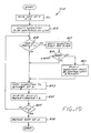
- FIG. 15 shown therein if a flow diagram illustrating in greater detail the functions provided pursuant to the function block 330 of FIG. 13 for fetching and copying a whole TILE.
- a copy of the current start address A is saved.
- the height H is fetched from the selected TILE table as indicated by the function block 513.
- the height H is used as a pointer to a specific one of the stacked bytes (slices) comprising the PATTERN with the top slice corresponding to the height H as fetched from the TILE table.
- the slice of the pattern corresponding to the current value of the height H is copied to the byte identified by the address A.
- the byte address A is incremented by W (the raster width in bytes), and the height H is decremented by one.
- FIG. 16 shown therein is a flow diagram illustrating in greater detail the functions provided pursuant to the function block 330 of FIG. 13 for fetching and copying the last TILE. Pursuant to the function block 611, a copy of the current TILE start address A is saved.
- the slice (one byte) of the PATTERN corresponding to the current value of the height H′ is fetched from the TILE table.
- the slice is AND'd with the MASK (B) and the the resulting byte is copied to the bitmap memory at the byte address A.
- the byte address A is incremented by W, and the height H′ is decremented by one.
- the PROFILE data and the X-SECTION data are utilized to provide raster data for vectors in octant C. Specifically, the PROFILE data is scanned from the most significant bit (MSB) to the least significant bit (LSB), which is left to right in the schematic representation of FIG. 4.
- FIG. 17 illustrates the result of applying the PROFILE data to the X-SECTION data associated with the TILE data of FIG. 4.
- a zero bit in the PROFILE indicates that the current X-SECTION data is to be copied as is, while a one bit indicates that the current X-SECTION should be shifted by one pixel (bit) and then copied.
- the PROFILE data and the X-SECTION data in essence cooperate to create a bitmap image of the PATTERN data that is rotated 90 degrees clockwise and mirrored about a line parallel to the X-axis.
- FIG. 18 shown therein is a flow diagram for rasterizing a line in octant C.
- the set-up data calculated pursuant to the flow diagram of FIG. 11 is fetched.
- Such set-up data includes the start address (byte address A, bit location B) of the vector to be rasterized, the slope M of the line, the initial accumulator value ACC, and the number of complete TILES N to be used.
- the starting TILE boundary is adjusted to coincide with the beginning (top) endpoint of the vector to be rasterized. Thus, only one end of a line in octant C will require a partial TILE.
- the raster data for the starting end portion is copied to the bitmap memory.
- such end portion comprises a rectangular array of pixels generally centered about the endpoint (A,B) and matched to the line width.
- a scaled slope M′ is calculated by multiplying the previously calculated slope M by 8. This scaled slope M′ will be utilized in subsequent calculations. Also, pursuant to the function 715, the TILE data for the slope M′ is accessed. Pursuant to the function block 717, the X-SECTION data is fetched.
- a selected TILE is fetched and copied to the bitmap memory.
- the function provided pursuant to the function block 710 will be discussed in further detail herein.
- the accumulator value ACC is updated by adding the scaled slope M′ thereto. Also, the bit address B is updated by subtracting the integer portion of the accumulator AC from the current value of B.
- a determination is made as to whether the bit location has become negative. If so, a byte boundary has been crossed, and the byte address A and the bit address B are updated pursuant to the function block 723. Specifically, the byte address A is incremented by one, while the bit location B is updated to the result of B modulo 8.
- the last partial TILE is copied to the bitmap memory, and the endpoint block is copied to the bitmap memory.
- FIG. 19 shown therein is a flow diagram in greater detail the functions provided pursuant to the function block 710 of FIG. 18.
- a copy of the current value of the byte address A is stored, and the height H is set to 8.
- the X-SECTION data is centered on the mathematical line pursuant to appropriate modulo arithmetic with reference to the location of the set bits of the X-SECTION data.
- the byte address A is updated by incrementing the current byte address by one pursuant to the function block 821. Also, the X-SECTION data including the carry is shifted to the left by eight positions. Control then transfers to the function block 823.
- the X-SECTION data is copied to the bit map at the current byte address.
- the byte address A is updated by adding W thereto. (It should be recalled that W is the width of the raster in bytes.) Further, the height H is decremented by one; and the PROFILE data is added to itself, which is the equivalent shifting left by one position.
- a determination is made as to whether the current value of the height H is equal to zero. If it is not, control transfers to the function block 815. If the current value of the height H is equal to zero, which indicates that the complete TILE has been copied, the byte address A is restored pursuant to the function 829 to the value saved pursuant to the function block 811. Rasterization of a TILE for a vector in octant C is now complete.
- the last partial TILE can be stored in the bitmap memory pursuant to a processing flow similar to that shown in FIG. 19, except that the last TILE height H′ is used as the counter.
- Lines in octants A and B have mirror images in octants D and C, respectively, about a line parallel to the X axis. It should be appreciated that the distinction between a line in octant A and its mirror image in octant D is the sign of its slope, and more particularly the sign the difference between the Y coordinates of the end points. The same distinction applies to a line in the octant B and its mirror image in the octant C. Based upon these relationships, the foregoing processes for using the TILE information can be utilized to rasterize lines in octants A and B with the changes described herein.
- a line in octant C is drawn by centering the X-SECTION data on the mathematical line at the starting endpoint (X1,Y1) and then moving in the positive X direction, sequentially copying the X-SECTION data as shifted in the positive Y direction pursuant to the PROFILE data. It is contemplated that a line in octant B can be rasterized using the same TILE data as that used for its mirror image in octant C.
- a line in octant D is drawn by centering the PATTERN data on the mathematical line at the starting endpoint (X1,Y1) pursuant to the N_HALF_WIDTH and the P_HALF_WIDTH data and then moving in the positive Y direction, using the integer portion of the accumulator value ACC to determine the byte address A at which to copy the TILE selected using the fractional portion of the accumulator value ACC pursuant to the flow diagram of FIG. 13. It is contemplated that a line in octant A can be rasterized using the same PATTERN data used for its mirror image in octant D.
Landscapes
- Engineering & Computer Science (AREA)
- Theoretical Computer Science (AREA)
- Physics & Mathematics (AREA)
- General Physics & Mathematics (AREA)
- General Engineering & Computer Science (AREA)
- Human Computer Interaction (AREA)
- Image Generation (AREA)
- Controls And Circuits For Display Device (AREA)
- Image Processing (AREA)
- Digital Computer Display Output (AREA)
Applications Claiming Priority (2)
| Application Number | Priority Date | Filing Date | Title |
|---|---|---|---|
| US07/211,789 US5028848A (en) | 1988-06-27 | 1988-06-27 | Tile vector to raster conversion method |
| US211789 | 1988-06-27 |
Publications (3)
| Publication Number | Publication Date |
|---|---|
| EP0348631A2 true EP0348631A2 (de) | 1990-01-03 |
| EP0348631A3 EP0348631A3 (de) | 1992-01-02 |
| EP0348631B1 EP0348631B1 (de) | 1995-06-28 |
Family
ID=22788382
Family Applications (1)
| Application Number | Title | Priority Date | Filing Date |
|---|---|---|---|
| EP89107700A Expired - Lifetime EP0348631B1 (de) | 1988-06-27 | 1989-04-27 | Vektor-zu-Raster-Umwandlungsverfahren |
Country Status (6)
| Country | Link |
|---|---|
| US (1) | US5028848A (de) |
| EP (1) | EP0348631B1 (de) |
| JP (1) | JP2925587B2 (de) |
| KR (1) | KR0150784B1 (de) |
| CA (1) | CA1322796C (de) |
| DE (1) | DE68923227T2 (de) |
Cited By (2)
| Publication number | Priority date | Publication date | Assignee | Title |
|---|---|---|---|---|
| EP0926627A1 (de) * | 1997-12-23 | 1999-06-30 | STMicroelectronics Limited | Verfahren zur Steuerung der Ausgabeeinrichtung |
| EP1406213A4 (de) * | 2001-06-21 | 2009-01-14 | Hi Corp | Informationsprozessor |
Families Citing this family (26)
| Publication number | Priority date | Publication date | Assignee | Title |
|---|---|---|---|---|
| US5164711A (en) * | 1990-02-08 | 1992-11-17 | International Business Machines Corporation | System and method for generating graphical output |
| JPH0561980A (ja) * | 1991-09-04 | 1993-03-12 | Nec Corp | 線分描画装置 |
| US5371843A (en) * | 1992-10-16 | 1994-12-06 | International Business Machines Corporation | Method and system for filling non-complex polygons using vertical spans |
| US6266455B1 (en) * | 1996-03-04 | 2001-07-24 | Copyer Co. Ltd. | Image processor |
| US6791547B2 (en) * | 2001-10-18 | 2004-09-14 | Hewlett-Packard Development Company, L.P. | Auxiliary active region determination for line width generation in regionalized rasterizer displays |
| US7293088B2 (en) | 2003-07-28 | 2007-11-06 | Cisco Technology, Inc. | Tag location, client location, and coverage hole location in a wireless network |
| US7286515B2 (en) * | 2003-07-28 | 2007-10-23 | Cisco Technology, Inc. | Method, apparatus, and software product for detecting rogue access points in a wireless network |
| US6990428B1 (en) | 2003-07-28 | 2006-01-24 | Cisco Technology, Inc. | Radiolocation using path loss data |
| US7260408B2 (en) * | 2004-02-20 | 2007-08-21 | Airespace, Inc. | Wireless node location mechanism using antenna pattern diversity to enhance accuracy of location estimates |
| US7286833B2 (en) * | 2004-02-27 | 2007-10-23 | Airespace, Inc. | Selective termination of wireless connections to refresh signal information in wireless node location infrastructure |
| US7205938B2 (en) * | 2004-03-05 | 2007-04-17 | Airespace, Inc. | Wireless node location mechanism responsive to observed propagation characteristics of wireless network infrastructure signals |
| US7116988B2 (en) * | 2004-03-16 | 2006-10-03 | Airespace, Inc. | Location of wireless nodes using signal strength weighting metric |
| US7433696B2 (en) * | 2004-05-18 | 2008-10-07 | Cisco Systems, Inc. | Wireless node location mechanism featuring definition of search region to optimize location computation |
| US7286835B1 (en) * | 2004-09-10 | 2007-10-23 | Airespace, Inc. | Enhanced wireless node location using differential signal strength metric |
| US7047014B1 (en) * | 2004-11-05 | 2006-05-16 | Airespace, Inc. | Raster-to-vector conversion operations adapted to modeling of RF propagation |
| US7616555B2 (en) * | 2006-10-03 | 2009-11-10 | Cisco Technology, Inc. | Minimum variance location estimation in wireless networks |
| US7835749B1 (en) | 2006-10-03 | 2010-11-16 | Cisco Technology, Inc. | Location inspector in wireless networks |
| US7626969B2 (en) * | 2006-10-04 | 2009-12-01 | Cisco Technology, Inc. | Relative location of a wireless node in a wireless network |
| US7983667B2 (en) | 2006-10-05 | 2011-07-19 | Cisco Technology, Inc. | Radio frequency coverage map generation in wireless networks |
| US7734412B2 (en) * | 2006-11-02 | 2010-06-08 | Yahoo! Inc. | Method of client side map rendering with tiled vector data |
| US7904092B2 (en) * | 2007-01-04 | 2011-03-08 | Cisco Technology, Inc. | Locally adjusted radio frequency coverage maps in wireless networks |
| US7925100B2 (en) * | 2007-07-31 | 2011-04-12 | Microsoft Corporation | Tiled packaging of vector image data |
| US7982749B2 (en) * | 2008-01-31 | 2011-07-19 | Microsoft Corporation | Server-based rasterization of vector graphics |
| WO2012103794A1 (zh) * | 2011-01-31 | 2012-08-09 | 北京壹人壹本信息科技有限公司 | 一种手写原笔迹的实现方法、实现装置及电子装置 |
| JP5852374B2 (ja) * | 2011-09-07 | 2016-02-03 | 株式会社Screenホールディングス | 描画装置および描画方法 |
| RU2592399C2 (ru) * | 2014-10-31 | 2016-07-20 | Общество с ограниченной ответственностью "КЛЕВЕРЕНС СОФТ" | Способ кодирования и записи данных на rfid-метку |
Family Cites Families (14)
| Publication number | Priority date | Publication date | Assignee | Title |
|---|---|---|---|---|
| US4205389A (en) * | 1976-09-24 | 1980-05-27 | General Electric Company | Apparatus for generating a raster image from line segments |
| US4254467A (en) * | 1979-06-04 | 1981-03-03 | Xerox Corporation | Vector to raster processor |
| US4425559A (en) * | 1980-06-02 | 1984-01-10 | Atari, Inc. | Method and apparatus for generating line segments and polygonal areas on a raster-type display |
| US4451895A (en) * | 1980-07-17 | 1984-05-29 | Telesis Corporation Of Delaware, Inc. | Interactive computer aided design system |
| US4458330A (en) * | 1981-05-13 | 1984-07-03 | Intergraph Corporation | Banded vector to raster converter |
| EP0112942B1 (de) * | 1982-12-30 | 1987-03-11 | International Business Machines Corporation | Verfahren und Einrichtung zur grafischen Darstellung |
| US4601002A (en) * | 1983-01-06 | 1986-07-15 | The United States Army Corps Of Engineers As Represented By The Secretary Of The Army | Digital technique for constructing variable width lines |
| DE3379004D1 (en) * | 1983-06-30 | 1989-02-23 | Ibm | Method of storing characters in a display system |
| US4549275A (en) * | 1983-07-01 | 1985-10-22 | Cadtrak Corporation | Graphics data handling system for CAD workstation |
| US4611268A (en) * | 1984-01-06 | 1986-09-09 | Goetz Sandor | Method and electronic apparatus for optimal arrangement of shapes having at least two dimensions |
| JPS60179877A (ja) * | 1984-02-28 | 1985-09-13 | Canon Inc | パターン太め装置及び方法 |
| NL8502643A (nl) * | 1985-09-27 | 1986-04-01 | Oce Nederland Bv | Werkwijze voor het genereren van lijnstukken. |
| JPS62109182A (ja) * | 1985-11-07 | 1987-05-20 | Fujitsu Ltd | 高速直線描画方式 |
| JPH033084A (ja) * | 1989-05-31 | 1991-01-09 | Ricoh Co Ltd | 直線描画方法 |
-
1988
- 1988-06-27 US US07/211,789 patent/US5028848A/en not_active Expired - Lifetime
-
1989
- 1989-04-27 DE DE68923227T patent/DE68923227T2/de not_active Expired - Fee Related
- 1989-04-27 EP EP89107700A patent/EP0348631B1/de not_active Expired - Lifetime
- 1989-06-26 CA CA000603943A patent/CA1322796C/en not_active Expired - Fee Related
- 1989-06-27 JP JP1165136A patent/JP2925587B2/ja not_active Expired - Fee Related
- 1989-06-27 KR KR1019890008873A patent/KR0150784B1/ko not_active Expired - Fee Related
Cited By (4)
| Publication number | Priority date | Publication date | Assignee | Title |
|---|---|---|---|---|
| EP0926627A1 (de) * | 1997-12-23 | 1999-06-30 | STMicroelectronics Limited | Verfahren zur Steuerung der Ausgabeeinrichtung |
| US6903750B2 (en) | 1997-12-23 | 2005-06-07 | Stmicroelectronics Limited | Controlling an output device |
| EP1406213A4 (de) * | 2001-06-21 | 2009-01-14 | Hi Corp | Informationsprozessor |
| EP1406214A4 (de) * | 2001-06-21 | 2009-01-14 | Hi Corp | Informationsprozessor |
Also Published As
| Publication number | Publication date |
|---|---|
| KR900000763A (ko) | 1990-01-30 |
| US5028848A (en) | 1991-07-02 |
| EP0348631A3 (de) | 1992-01-02 |
| DE68923227T2 (de) | 1995-11-30 |
| EP0348631B1 (de) | 1995-06-28 |
| CA1322796C (en) | 1993-10-05 |
| DE68923227D1 (de) | 1995-08-03 |
| JP2925587B2 (ja) | 1999-07-28 |
| JPH0244482A (ja) | 1990-02-14 |
| KR0150784B1 (ko) | 1998-10-15 |
Similar Documents
| Publication | Publication Date | Title |
|---|---|---|
| US5028848A (en) | Tile vector to raster conversion method | |
| US5115402A (en) | Scan-conversion process and processor for converting a graphic primitive to a pixel map | |
| US4851825A (en) | Grayscale character generator and method | |
| US5303334A (en) | System for generating a rasterized graphic image | |
| US4967392A (en) | Drawing processor for computer graphic system using a plurality of parallel processors which each handle a group of display screen scanlines | |
| US5428728A (en) | Method and apparatus for outline font character generation in dot matrix devices | |
| JP3071357B2 (ja) | 曲線を描く装置及び方法 | |
| JPH06266847A (ja) | ラスタ化されたオブジェクトを表示する方法および装置 | |
| EP0592770B1 (de) | Verfahren zum Ausfüllen der Bildpunkte innerhalb eines Polygons | |
| US5489920A (en) | Method for determining the optimum angle for displaying a line on raster output devices | |
| EP0344686B1 (de) | Abschneidungsverfahren und -verarbeitungsgerät | |
| US5276790A (en) | Fast vertical scan-conversion and filling method and apparatus for outline font character generation in dot matrix devices | |
| EP0231060A2 (de) | Festzeichenreihenabschneidung in einem graphischen Anzeigesystem | |
| US5771047A (en) | Graphics computer | |
| US4849907A (en) | Draw processing method and apparatus | |
| EP0301253B1 (de) | Erzeugung von Linien in einem Anzeigesystem | |
| US5317650A (en) | Determination of the arc length of a curve | |
| JP3009525B2 (ja) | ベクトル画像描画装置 | |
| US5627956A (en) | Run slice line draw engine with stretching capabilities | |
| US5297244A (en) | Method and system for double error antialiasing in a computer display system | |
| US5670981A (en) | Method for mapping a source pixel image to a destination pixel space | |
| US6677950B1 (en) | Graphics computer | |
| EP0981106A2 (de) | Verfahren und Gerät zur massstäblichen Umformung von Bildern | |
| EP0339758B1 (de) | Bildverarbeitungsgerät zur Ausführung von projektiven Transformationen | |
| JPS63208898A (ja) | 文字処理装置 |
Legal Events
| Date | Code | Title | Description |
|---|---|---|---|
| PUAI | Public reference made under article 153(3) epc to a published international application that has entered the european phase |
Free format text: ORIGINAL CODE: 0009012 |
|
| AK | Designated contracting states |
Kind code of ref document: A2 Designated state(s): DE FR GB IT |
|
| PUAL | Search report despatched |
Free format text: ORIGINAL CODE: 0009013 |
|
| AK | Designated contracting states |
Kind code of ref document: A3 Designated state(s): DE FR GB IT |
|
| 17P | Request for examination filed |
Effective date: 19920221 |
|
| 17Q | First examination report despatched |
Effective date: 19931110 |
|
| GRAA | (expected) grant |
Free format text: ORIGINAL CODE: 0009210 |
|
| AK | Designated contracting states |
Kind code of ref document: B1 Designated state(s): DE FR GB IT |
|
| REF | Corresponds to: |
Ref document number: 68923227 Country of ref document: DE Date of ref document: 19950803 |
|
| ET | Fr: translation filed | ||
| ITF | It: translation for a ep patent filed | ||
| PLBE | No opposition filed within time limit |
Free format text: ORIGINAL CODE: 0009261 |
|
| STAA | Information on the status of an ep patent application or granted ep patent |
Free format text: STATUS: NO OPPOSITION FILED WITHIN TIME LIMIT |
|
| 26N | No opposition filed | ||
| REG | Reference to a national code |
Ref country code: GB Ref legal event code: 732E |
|
| REG | Reference to a national code |
Ref country code: FR Ref legal event code: TP |
|
| REG | Reference to a national code |
Ref country code: GB Ref legal event code: IF02 |
|
| PGFP | Annual fee paid to national office [announced via postgrant information from national office to epo] |
Ref country code: DE Payment date: 20070531 Year of fee payment: 19 |
|
| PGFP | Annual fee paid to national office [announced via postgrant information from national office to epo] |
Ref country code: GB Payment date: 20070425 Year of fee payment: 19 |
|
| PGFP | Annual fee paid to national office [announced via postgrant information from national office to epo] |
Ref country code: IT Payment date: 20070523 Year of fee payment: 19 |
|
| PGFP | Annual fee paid to national office [announced via postgrant information from national office to epo] |
Ref country code: FR Payment date: 20070417 Year of fee payment: 19 |
|
| GBPC | Gb: european patent ceased through non-payment of renewal fee |
Effective date: 20080427 |
|
| PG25 | Lapsed in a contracting state [announced via postgrant information from national office to epo] |
Ref country code: DE Free format text: LAPSE BECAUSE OF NON-PAYMENT OF DUE FEES Effective date: 20081101 |
|
| REG | Reference to a national code |
Ref country code: FR Ref legal event code: ST Effective date: 20081231 |
|
| PG25 | Lapsed in a contracting state [announced via postgrant information from national office to epo] |
Ref country code: FR Free format text: LAPSE BECAUSE OF NON-PAYMENT OF DUE FEES Effective date: 20080430 |
|
| PG25 | Lapsed in a contracting state [announced via postgrant information from national office to epo] |
Ref country code: GB Free format text: LAPSE BECAUSE OF NON-PAYMENT OF DUE FEES Effective date: 20080427 |
|
| PG25 | Lapsed in a contracting state [announced via postgrant information from national office to epo] |
Ref country code: IT Free format text: LAPSE BECAUSE OF NON-PAYMENT OF DUE FEES Effective date: 20080427 |