EP0348528A1 - Navigationssystem für fahrzeuge - Google Patents
Navigationssystem für fahrzeuge Download PDFInfo
- Publication number
- EP0348528A1 EP0348528A1 EP89900881A EP89900881A EP0348528A1 EP 0348528 A1 EP0348528 A1 EP 0348528A1 EP 89900881 A EP89900881 A EP 89900881A EP 89900881 A EP89900881 A EP 89900881A EP 0348528 A1 EP0348528 A1 EP 0348528A1
- Authority
- EP
- European Patent Office
- Prior art keywords
- destination
- information
- point
- departure
- data
- Prior art date
- Legal status (The legal status is an assumption and is not a legal conclusion. Google has not performed a legal analysis and makes no representation as to the accuracy of the status listed.)
- Withdrawn
Links
Images


Classifications
-
- G—PHYSICS
- G01—MEASURING; TESTING
- G01C—MEASURING DISTANCES, LEVELS OR BEARINGS; SURVEYING; NAVIGATION; GYROSCOPIC INSTRUMENTS; PHOTOGRAMMETRY OR VIDEOGRAMMETRY
- G01C21/00—Navigation; Navigational instruments not provided for in groups G01C1/00 - G01C19/00
- G01C21/26—Navigation; Navigational instruments not provided for in groups G01C1/00 - G01C19/00 specially adapted for navigation in a road network
- G01C21/34—Route searching; Route guidance
Definitions
- This invention relates to a navigation apparatus which, upon being provided with an input of a desired destination, furnishes course guidance by outputting guidance information for travel to the destination.
- a navigation apparatus provides course guidance for travel to a destination to a driver who is unfamiliar with the local geography. Recent years have seen extensive development of such navigation apparatus.
- a vehicular navigation apparatus relies upon so-called "route matching" in which a course is set from a starting point to a desired destination before the vehicle begins travelling, with course guidance being provided to the driver in accordance with the course set.
- a map is displayed on the screen of a CRT and the course is superimposed on the map when the driver designates a specific course.
- the distance to this intersection is displayed numerically or in the form of a graph.
- the driver When a turn is to be made at an intersection using such a navigation apparatus the driver observes the course disolaved on the map to decide the next intersection at which the turn is to be made, or the driver looks at the numeric or graphical display to ascertain the distance to the intersection where the turn is to be made, thereby determining the proper intersection.
- the code of an input intersection must be found in an intersection list and then entered from a keyboard or the like when a departure point is to be inputted. This requires time, labor and difficulty in use. In addition, since the departure point is not a precise intersection position, distance precision for pursuing the present position is poor.
- the conventional navigation apparatus is such that a course is set from a departure point to a destination before the vehicle begins travelling and course guidance is provided to the driver in accordance with the course set, as mentioned above. Consequently, a problem is that if the driver should happen to mistake, say, an intersection and stray from the set course, travel in accordance with the guidance provided by the navigation apparatus will not be able to continue unless the vehicle is returned to the set course. Furthermore, a decision as to whether or not a predetermined intersection has been passed as specified by the course guidance is premised upon detection of travelled distance or a left or right turn as detected by a distance sensor or steering angle sensor, respectively. In actuality, however, detection of travelled distance and steering angle is susceptible to considerable error, which can cause errors in judgment.
- the input method is one in which a transparent control panel mounted on the front of a CRT is pressed by a finger tip to make an input, as set forth in Japanese Patent Application Laid-Open No. 62-51000.
- the transparent control panel e.g., an infrared touch panel
- the transparent control panel includes light-receiving and light-emitting elements mounted in horizontal and vertical directions, respectively, on the screen of the display unit.
- the screen is pressed by a finger tip, pairs of elements between which light has been interrupted can be detected in the horizontal and vertical directions, whereby the position pressed by the finger tip is detected.
- the conventional infrared touch panel described above displays a plurality of selectable item positions on its screen and such a position is designated by the operator's finger, the selected position cannot always be designated accurately.
- the detection area of a selectable item is not sufficiently large and finger thickness cannot be ignored, as when the screen is viewed from an angle or a plurality of selectable positions are arranged close together and a border portion between positions is designated, and there are also instances where, owing to use of a light-interruption method, a detection position cannot be specified at a point touched a distance away from a position touched first on the display screen, as when the operator's finger is moved on the screen.
- the conventional navigation apparatus is such that a course is set from a departure point to a destination before the vehicle begins travelling and course guidance is provided to the driver in accordance with the course set, as mentioned above. Consequently, a problem is that if the driver should happen to mistake, say, an intersection and stray from the set course, travel in accordance with the guidance provided by the navigation apparatus will not be able to continue unless the vehicle is returned to the set course. Furthermore, a decision as to whether or not a predetermined intersection has been passed as specified by the course guidance is premised upon detection of travelled distance or a left or right turn as detected by a distance sensor or steering angle sensor, respectively. In actuality, however, detection of travelled distance and steering angle is susceptible to considerable error, which can cause errors in judgment.
- the present invention solves the foregoing problems.
- the present invention described in claims 1 through 3 in such that a reset switch is pressed when inputting a point of departure.
- the following routine is executed whenever the reset switch is pressed: First, when an initial point of departure is entered by pressing the reset switch, the data are written in a non-volatile area of a RAM 9b, then destination input and course guidance are executed. When the destination is attained, destination arrival processing is executed and the destination data are set as departure-point data. When "RETURN" is selected at the time of a subsequent destination input, departure-point data are read in from the non-volatile area of the RAM 9b and these data are set as destination data.
- the invention set forth in claim 4 is such that intersections adjacent to two intersections leading to, say, a previous guidance point or selected departure point, are retrieved. If the intersections are within a predetermined distance (e.g., 1 km) from the departure point and have intersection names, these are adopted as display intersections, a predetermined number (e.g., six) of the display intersections are displayed and it is possible to select these by a touch panel. Accordingly, the names of intersections within a predetermined range about the departure point are displayed on the display screen and a departure point can be selected from among them. As a result, the labor involved in making entry by code number as in the prior art can be eliminated, and entries can be made simply in one-touch fashion. In addition, even if a departure point is not an intersection, selection can be made by entering a code number. By adopting the departure point as an intersection, distance precision for pursuing the present position can be improved.
- a predetermined distance e.g. 1 km
- intersection names e.g., six
- the object of the present invention as set forth in claims 5 through 7 is to provide a navigation apparatus in which, through a simple system arrangement, appropriate guidance information can be outputted at any geographical point without a course being fixed. For example, as shown in Fig. 30, if an input in Roman characters is made after an input screen is displayed, an input-character buffer is cleared, one Roman character is inputted and the character is stored in the input-character buffer. Next, names corresponding to the character string in the character buffer are selected from a Roman character sort list and displayed on a menu screen, and then an item in the menu is selected. If a selection can be made, the selected name data are read in and set in a predetermined area of a memory.
- guidance information for travel to a destination can be set at each and every geographical point by guidance information setting means.
- guidance information setting means if the present location is entered as a guidance location by guidance location input means, guidance information for travel from this geographical point to the destination will be displayed on output means.
- guidance information can be obtained from any geographical point.
- merely entering a trigger signal makes it possible to easily set the next geographical point as a guidance point in accordance with the guidance information for travel to the destination.
- the object of the present invention as set forth in claim 8 is to make it possible to make a selective input on a touch panel in an accurate manner.
- a selective input on a touch panel For example, as shown in Fig. 11, "SIGHTSEEING”, LODGINGS, "DINING ' , SOUVENIRS”, “CODE NC. INPUT”, “RETURN” are displayed in red as selectable items, and a desired genre is selected by touch-panel input.
- the input display section is displayed entirely in the color red.
- a confirmation screen is displayed.
- the selected item is backlighted in, say, the color blue, while the other items appear in dark blue, so that the driver may easily confirm the selection made.
- confirmation keys "CANCEL” and “OK” are displayed in red. Accordingly, selective input on the touch panel can be performed in accurate fashion. By always causing the confirmation screen to be displayed before selecting a destination, it is possible to eliminate the danger of being guided to a different destination and destinations can be entered accurately.
- Fig. 1 is a view illustrating the construction of an embodiment of a navigation apparatus according to the present invention
- Fig. 2 is a view illustrating one example of a route sequence
- Fig. 3 is a view for describing the flew of navigation processing
- Fig. 4 a view for describing course search processing
- Figs. 5 through 9 are views for describing an example of the structure of data according to the invention
- Fig. 10 is a flowchart shewing an example of a destination input method
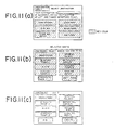
- Fig. 11 is a view illustrating examples of screens in destination input
- Fig. 12 and 13 are views for describing the flow of departure-point input processing
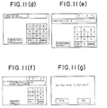
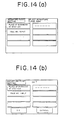
- Fig. 14 is a view showing examples of screens in departure-point input
- Fig. 1 is a view illustrating the construction of an embodiment of a navigation apparatus according to the present invention
- Fig. 2 is a view illustrating one example of a route sequence
- Fig. 3 is a view for describing the flew of navigation processing
- Fig. 4
- Fig. 15 is a view for describing the arrangement of storage areas;
- Fig. 16 is a view for describing a road network;
- Fig. 17 is a view for describing intersection data;
- Fig. 18 is a view for describing road number data;
- Figs. 19, 20, 21 are views showing the control flow of a departure-point input method;
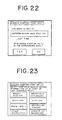
- Figs. 22 and 23 are views illustrating examples of display screens in departure-point input;
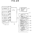
- Fig. 24 is a view illustrating the construction of another embodiment of a navigation apparatus according to the present invention;
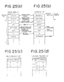
- Figs. 25 and 26 are views for describing another example of the structure of data according to the invention;
- Fig. 27 is a flowchart showing an example of a present-position input method;
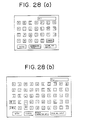
- FIGS. 28 and 29 are views illustrating examples of display screens for present-position input
- Figs. 30 and 31 are views for describing the flow of processing of the present-position input method
- Fig. 32 is a view showing the structure of an infrared touch panel. Best Mode for Carrying Out the Invention
- Fig. 1 Shown in Fig. 1 are an input unit 1, a CPU 2, a display unit 3 such as a CRT or liquid crystal display panel, and a memory unit 4.
- the input unit 1 is provided with input means for departure-point input 5, destination input 6, present-position input and trigger input, these inputs being made by keyboard, touch panel, light pen, mouse or voice input.
- the memory unit 4 is a memory such as a CD-ROM in which network data indicative of geographical points, namely desired destination and present position, and other information are stored in advance. As will be described below, map data 10, a list 11 of intersections, a list 12 of destinations, road data 13 and a list 14 of region names are stored.
- the CPU 2 When a destination is designated by an input from the input means 1, the CPU 2 performs an exchange with a program, stored in a ROM 9b, in order to set information for travel to the destination, by a method such as course exploration, in accordance with each geographical point stored in the memory unit 4.
- the CPU stores this information in a memory such as a RAM 9b.
- the RAM 9b is provided with a non-volatile area for storing departure-point data (east longitude, north latitude, etc.).
- departure-point data east longitude, north latitude, etc.
- the data in this non-volatile area can be rewritten. Data written in are preserved until the reset switch is pressed again and a geographical point is entered. Data will not be erased even if an ignition switch is turned off.
- the display unit 3 When present-position information is entered by the input means 1, the display unit 3 outputs guidance information for this point. If only intersections serve as geographical points, the outputted guidance information is that for travel to the next intersection, such as an indication of a left or write turn, at the intersection serving as the guidance point. In a case where there is a second intersection encountered immediately after turning at the aforementioned next intersection, it is of course possible for the outputted guidance information to include the direction of the first turn along with information designating the proper lane to take after the turn, as well as the direction of the second turn and the associated guidance information. For example, the display unit can output guidance information relating to a course leading to a desired destination in accordance with the path sequence a, b, c, ... shown in Fig. 2.
- a course search mode is established in which information for travel to the desired destination is set for all geographical points with the exception of the entered desired destination [step 21.
- course search ends a present position input mode is established, in which the driver inputs the code of his present position [step 31. When this is done, the direction of forward travel from this position is outputted [step 41.
- the driver inputs an intersection verification trigger [a start input, step 51, information for attaining the destination at the next intersection is outputted (step 61.
- monitoring is performed [step 71 to see whether the intersection verification trigger or a signal from a present-position input button has been entered. If the intersection verification trigger has been entered, the program returns to the processing of step 6.
- the program returns to the processing of step 3.
- a trigger is inputted each time an intersection is verified providing that the vehicle is travelling as per instructions. If the vehicle strays from the instructed course and the driver notices this only after the vehicle has travelled to another intersection, the present-position input button is pressed. Accordingly, whenever a trigger is inputted, guidance information relating to an intersection on a route leading to the desired destination is outputted in sequential fashion.
- the present-position input button is pressed, the present position input mode is established.
- step 2 When the course exploration input mode is established, as shown in Fig. 4(a), first the desired destination is set in a work area [step 11], after which forward directions from intersections near the destination are set [step 12 ]. As shown in Fig. 4(b), the set forward directions include forward directions d 1 at intersections before the destination, and forward directions d 2 at intersections before the first-mentioned intersections. It is permissible to execute this course search after the processing of step 3 in Fig. 3, in which case course search would be performed whenever present position is inputted. Furthermore, since guidance information is outputted in response to the trigger input in accordance with the route set as a result of course search, the pertinent intersections are limited in number. Accordingly, it will suffice to provide guidance information solely for the minimum number of intersections.
- Figs. 5 through 9 illustrate the structure cf data in accordance with the invention.
- Fig. 5 is a diagram useful in describing the fundamental approach adopted in forming map data.
- a map is not construed merely as but also includes ncdes, which are points having useful guidance information (e.g., bridges, rivers, buildings, gasoline stations, etc. at geographical points between intersections.
- nodes indicate point data representing map coordinates
- Arcs indicate line data and represent portions of the roads.
- a landmark serving as useful guidance information can be provided as data between roads (i.e., between two arcs) connecting node numbers on either side of a node number n of an intersection depicted in Fig. 5(b).
- Fig. 6 illustrates node series data. What is stored are east longitude and north latitude, namely the coordinates of the pertinent geographical point, for each node number, as well as the attribute which distinguishes the effective guidance information (e.g., bridges, rivers, buildings, gasoline stations) as data for each node number.
- east longitude and north latitude namely the coordinates of the pertinent geographical point, for each node number, as well as the attribute which distinguishes the effective guidance information (e.g., bridges, rivers, buildings, gasoline stations) as data for each node number.
- Fig. 7 illustrates an example of an intersection list, in which there are stored the node numbers of the intersections, the intersection names, the intersection numbers (numbers assigned only to those of the nodes that are intersections), the node numbers of two connecting nodes, as described above with reference to Fig. 5(b), the names of landmarks and attributes.
- Fig. 8 illustrates an example of a destination list, in which there are stored code numbers, the names of destinations, parking lot numbers, the numbers of two connecting intersections connecting a desired destination, the directions of parking lots (whether a parking lot is on the left or right side of a road or straight ahead), the numbers of photographs of connecting intersections, the numbers of photographs of parking lot exits, block data for each region, and coordinates (east longitude, west latitude).
- the arrangement is such that the attribute of each desired destination is distinguishable by genre.
- the following numbers can be assigned to the most significant bit of code number to indicate genre: 0 (sightseeing), 1 (public facility), 2 (lodgings), 3 (dining), 4 (place of business), 5 (gasoline station), 6 (intersection), 7 (parking lot), 8 (souvenirs), and other attribute data can be provided if desired.
- These desired destination data indicate parking areas near the desired destinations. If a desired destination is a parking lot, the driver is informed of the connecting intersection numbers, the direction of the parking lot (whether it is on the left or right side of a road or straight ahead), the photograph numbers of the connecting intersections and the photograph numbers of the parking lot exit. Thus, the driver is guided in positive fashion until the vehicle arrives at its final destination.
- Fig. 9(a) illustrates an example of road data.
- each road is assigned a road number(s) along with the direction(s) of traffic flow.
- the stored road data include, for each road number, the node starting and end points of the road the number of a road having the same starting point, the number of a road having the same end point, road width, information relating to prohibitions, information relating to guidance not required (as when the driver need only continue travelling straight ahead), photograph numbers, the numbers of nodes, the leading addresses of node series data, etc.
- Fig. 10 is a flowchart of the associated processing.
- a step 101 calls for the screen shown in Fig. ll(a) to be displayed as a desired destination input. This screen is for indicating the genre of the destination. Items which appear frequently, such as "SIGHTSEEING”, “LODGINGS”, “DINING”, SOUVENIRS”, “CODE NO. INPUT”, "RETURN” are displayed in red as selectable items, and a genre is selected by touch-panel input at step 102.
- step 103 it is determined at step 103 whether "RETURN'' on the screen of Fig. 11(a) has been inputted. If the answer is NO, it is determined at step 106 whether "CODE NO.” has been inputted. If the answer received here is YES, then the program proceeds to step 112.
- step 106 the program proceeds to step 107, at which a list of parking lots (destinations) for the selected item are read in from the CD-ROM, whereupon the screen shown in Fig. 11(b) is displayed (step 103).
- a voice track "SELECT YOUR DESIRED DESTINATION” is played.
- items are displayed in the order of their frequency.
- PRECEDING PAGE or "NEXT PAGE” key, destination parking lots can be selectively designated. All of the input display sections are displayed in the color red. The last item in the display is the "CODE INPUT NO. INPUT" item. If "PRECEDING PAGE" is entered at the first page, the program returns to step 101.
- a confirmation screen shown in Fig. 11(c) is displayed at step 110.
- the selected item is backlighted in, say, the color blue, while the other items appear in dark blue, so that the driver may easily confirm the selection made.
- OK is pressed, the program returns to step 108. If OK is pressed, it is determined at step 111 whether the name of a parking lot has been inputted or a code number. If the name of a parking lot is the desired destination, the program proceeds to step 119, where data corresponding to the name of the parking lot are read from the CD-ROM and set in the memory area of the CPU.
- a code number input screen shown in Fig. ll(d) is displayed at step 112, after which a desired parking lot code number is inputted from the touch panel at step 113. It is then determined at a step 114 whether the code number designation is mistaken. If it is, step 115 calls for display of a message reading "CODE NO. DESIGNATION IS INCORRECT" and the program returns to step 113. If the code number designation is correct, then it is determined at step 116 whether the code number is an intersection code. If it is not an intersection code, the program proceeds to step 118, at which the desired destination is displayed automatically, as shown in Fig. ll(e). If the "OK" key is pressed, the program proceeds to step 119, at which data corresponding to parking lot name are read out of the CD-ROM and set in the memory area of the CPU. The program returns to step 113 if "CANCEL” is pressed.
- "RETURN” is inputted at step 101 in execution of the above routine, the screen of Fig. 11(g) is displayed through steps 103, 104. If the driver presses "OK”, the initial departure-point data are copied in the desired destination storage area (step 105).
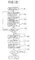
- Fig. 12 describe flow when the reset switch characterizing the present invention is pressed.
- the a reset switch is pressed when inputting a point of departure.
- the following routine is executed whenever the reset switch is pressed: First, when an initial point of departure is entered in a case where the reset switch is pressed, the data are written in a non-volatile area of the RAM 9b in a region thereof rewritable as initial departure-point data only when the reset switch is pressed, and these data are written in also as departure-point data (steps 131 - 133). Next, destination input and course guidance are executed (steps 134, 135). When the destination is attained, destination arrival processing is executed (steps 103, 105 in Fig.
- Fig. 13 illustrates the flow of processing for the initial departure-point input of Fig. 152.
- the departure-point selection screen shown in Fig. 14 is displayed at step 152.
- a place of besiness imaging that this is a car rental business
- a selection confirmation screen display is outputted at step 154, as shown in Fig. 14(b).
- the code-number input screen is displayed, just as in Figs. ll(d) and (e)
- a code number is entered by the touch panel and a screen for confirming the name of the entered location is displayed (steps 156 - 158).
- Figs. 16 through 18 illustrate another example of the structure of data, in which Fig. 16 illustrates network data having numbers assigned to roads and intersections.
- the intersection data include, in correspondence with each intersection, positional coordinates (east longitude, north latitude), the smallest road number of the roads exiting the intersection, the intersection number of a block alongside, the number of roads exiting and the intersection name.
- the network data are divided into a number of blocks. Therefore, if an intersection crossing into an adjacent block exists and the vehicle makes a transition to the adjacent block, the abovementioned intersection number of the block along side will be necessary.
- Fig. 18 illustrates road number data. Scored in correspondence with each road number are the number of the intersection which is the end point and the next road number having the same starting point. It should be noted that the intersection list 12 shown in Fig. stores a correlation table of intersection numbers, code numbers and intersection names, and the destination list 13 stores code numbers, destination names, parking lot numbers, the numbers of two intersections connected to a destination (the destination being set between two intersections), positional coordinates and the like.
- Fig. 19 illustrates the main flow.
- step 101 it is determined whether an initial start is made after reset. In case of initial start, guidance starting point based on code number is entered by the touch panel or the like at step 104. If this is not initial start after reset, the screen shown in Fig. 22 is displayed and it is verified by the touch panel whether the present location is near the previous location (destination) at step 102. If "NO" is touched on the screen of Fig. 22 at step 103, the program proceeds to step 104. If "YES" is touched, the processing of a routine for displaying a peripheral intersection list is executed at step 105, and a screen of intersections with assigned names shown in Fig. 23 is displayed.
- step 106 a touch-panel input is made on the screen of Fig. 23.
- step 107 it is determined whether "OTHER INTERSECTION" has been selected If it has not been selected, processing ends; if it has, the departure point is entered by code number.
- Fig. 20 illustrates the processing of the routine of step 105 for displaying the peripheral intersection list.
- a peripheral intersection retrieval subroutine is executed at step 111. As will be described below, this is processing for retrieving intersections adjacent to two intersections K 1 , K 2 leading to the preceding guidance point or a selected point of departure.
- steps 112, 113 it is checked to determine whether each of the retrieved intersections has already been extracted. The following processing is executed with regard to an intersection that has not already been extracted. Specifically, it is determined at step 114 whether the intersection is within a predetermined distance (e.g., 1 km) of the point of departure. If the answer is "NO", the program jumps to step 119. If the intersection is within the predetermined distance, this is adopted as an intersection K 3 to be investigated next.
- a predetermined distance e.g. 1 km
- step 116 it is determined whether the intersection K 3 has an intersection name. If it does not have an intersection name, the program jumps to step 119; if it does, this intersection is made a display intersection C 1 and, at step 118, it is determined whether the number of display intersections is a predetermined number (e.g., six). If the number of intersections is not a predetermined number, it is determined at step 119 whether there is still an intersection to be checked. If there is, then the foregoing processing is repeated. The program returns when the number of display intersections reaches the predetermined number or when there are no longer intersections to be checked.
- a predetermined number e.g., six
- Fig. 21 illustrates the processing of the subroutine of step 111 for retrieving peripheral intersections.
- step 121 For example, of the two intersections K 1 , K 2 leading to the preceding guidance point or selected point of departure, assume that K 1 has the intersection numbers 1,2 indicated by the intersection data of Fig. 17. In such case, the smallest road number 1 of the roads exiting the No. 1 intersection and the number of roads 2 exiting the intersection are obtained at step 121.
- step 122 there are obtained from the road data of Fig. 18 the end point intersection number 3 of the abovementioned road number 1 and the next road number 2 having the same starting point, whereby there is obtained the end point intersection 2. It is then determined at step 123 whether the initially retrieved road and the road retrieved now are the same, namely whether all roads in a block exiting the intersection have been retrieved. If, when all roads have been retrieved, there is an intersection in an adjacent block, this intersection is retrieved and the foregoing processing is repeated, whereby intersections connected to intersection K 1 are retrieved (steps 124, 125).
- Fig. 24 there are shown input means 1, a CPU 2, a display unit 3 such as a CRT or liquid crystal display panel, and a memory unit 4.
- a keyboard 105 comprises a ten-key pad and function keys for inputting code numbers of predetermined geographical locations, such as a desired destination and present position (guidance point).
- a touch panel 106, light pen 107; mouse 108 or voice input means 109 are employed instead of the keyboard 105.
- the memory unit 4 is a memory such as a ROM in which network data indicative of geographical points, namely desired destination and present position, and other information are stored in advance.
- a region name list 110 a region name list 110, a landmark list 111, a region name frequency list 112, a landmark frequency list 113, a romaji (Roman character) sort file 114, a hiragana (the cursive Japanese syllabary) sort file 115 and intersection data 116 are stored.
- Figs. 25 and 26 illustrate the structure of data in this embodiment.
- Fig. 25(a) illustrates a list of region names collected over a comparatively wide area.
- a region number 0 represents "KYOTO".
- the list contains region names in kanji (Chinese characters), hiragana and Roman characters, code numbers, the storage addresses of a region name (landmark) list, the numbers of items of data in a region name (landmark) list, and initial frequency.
- Fig. 25(b) illustrates a landmark list of landmarks constituting lower-order information under region names, e.g., place names, intersection names and the names of rivers, bridges and buildings.
- the list contains names in kanji, hiragana and Roman characters, code numbers, east longitude and north latitude, initial frequency and attributes (genre information indicative of sightseeing, lodgings, dining, etc.). It can be arranged so that the region name list and landmark list are handled as intersection lists, and so that these can be made into lists of intersection names and landmarks between intersections.
- Figs. 25(c), (d) illustrate lists showing the frequency at which regions and landmarks are used. These are for being extracted with higher priority in a case where frequency of use is retrieved as data.
- Figs. 26(a), (b) show Roman character and hiragana sort files, respectively. Place names are arranged in alphabetical order or in the order of the Japanese syllabary, and data storage addresses are provided corresponding thereto, thereby shortening the time needed to retrieve the place names.
- Fig. 26(c) illustrates an example of intersection data. Stored as data in correspondence with the intersection code numbers are intersection names, whether or not traffic signals are present, and the code numbers of intersections to be traversed next. Thus, a variety of navigational information is displayed on a display screen.
- Fig. 27 illustrates an example of a method of inputting present location, in which (a) entails selecting a place name list of a region selected by designating a region name, and then selecting a particular place name and setting the related data, and (b) entails selecting, from a list, a place name corresponding to a genre selected by designating a genre such as sightseeing, lodgings or dining, and then selecting a particular place name and setting the related data.
- a place name list of a region selected by designating a region name and then selecting a particular place name and setting the related data
- a place name list of a region selected by designating a region name
- a particular place name and setting the related data entails selecting, from a list, a place name corresponding to a genre selected by designating a genre such as sightseeing, lodgings or dining, and then selecting a particular place name and setting the related data.
- the names of candidates are few, it is possible to perform direct name selection.
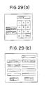
- Figs. 28(a), (b) and Fig. 29(a) illustrate display screens when input is made on the display by a touch panel, light pen, mouse or the like.
- Fig. 28(a) shows a Roman character input screen
- Fig. 29(a) a code number input screen.
- Fig. 29(b) depicts an example of a menu screen when a destination input is made. This illustrates a case in which "KY” is entered for retrieval and display of "KYOTO GOSHO, KIYOMIZU TEMPLE, KINKAKU TEMPLE".
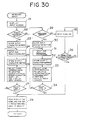
- Fig. 30 shows the flow of processing for name selection by keyboard.
- the input screen is displayed at step 21, after which it is determined at step 22 whether a Roman character input is made.
- an input character buffer is cleared, one Roman character is entered and this is stored in the input character buffer (steps 23 - 25).
- names corresponding to the character string in the character buffer are selected from the Roman character sort list and displayed on the menu screen (step 26), and then an item in the menu is selected (step 27). If a selection can be made, name data selected at step 28 is read in and set in a predetermined area of a memory. If an item selected is not on the menu screen, the program returns to step 24 and the foregoing processing is repeated.
- step 29 If the input is not a Roman character input at step 22, it is determined at step 29 whether the input is a hiraaana input. If it is a hiragana input, processing (steps 30 - 34), which is similar to the foregoing processing, is executed. If the input is not a hiragana input at step 29, a code number is entered (step 35). Then, if a name corresponds to the code number at step 36, the program prcceeds to step 28.
- Fig. 31 shows the flow of processing for name selection by keyboard. Though the processing is basically similar to that of Fig. 30, here the processing is such that the number of place names corresponding to the character string is made less than a predetermined number.
- the present invention is not limited to the foregoing embodiment but can be modified in various ways.
- an arrangement can be adopted in which a place name list of specific regions is stored on an IC card or CDROM.
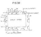
- Fig. 32 shows the structure of an infrared touch panel as an example of the touch panel 106.
- Light-emitting elements a 1 , a 2 , a 3 ,... a are arrayed horizontally and vertically on a display screen
- light-receiving elements b l , b 2 , b 3 , ... b n are arrayed horizontally and vertically on the display screen so as to oppose respective ones the light-emitting elements.
- the touched position is detected by pairs of the horizontal and vertical elements. This makes detection of position possible.
- destinations and intersections are entered as code numbers.
- hiragana or Roman character data are provided as the destination and intersection data and these are entered by character retrieval.
- the navigation apparatus identifies predetermined geographical points automatically by other means and changes over the guidance information delivered to the driver each time.
- the navigation apparatus of the present invention is mounted on an automotive vehicle so that even a driver unfamiliar with the roads can be guided to a desired destination automatically. For this reason, the apparatus of the invention is especially useful in a society where the aging are increasing in number.
Landscapes
- Engineering & Computer Science (AREA)
- Radar, Positioning & Navigation (AREA)
- Remote Sensing (AREA)
- Automation & Control Theory (AREA)
- Physics & Mathematics (AREA)
- General Physics & Mathematics (AREA)
- Navigation (AREA)
Applications Claiming Priority (6)
| Application Number | Priority Date | Filing Date | Title |
|---|---|---|---|
| JP333053/87 | 1987-12-28 | ||
| JP33305587A JPH01173823A (ja) | 1987-12-28 | 1987-12-28 | 車両用ナビゲーション装置の目的地入力方式 |
| JP33305387A JP2731387B2 (ja) | 1987-12-28 | 1987-12-28 | 車両用ナビゲーション装置 |
| JP333055/87 | 1987-12-28 | ||
| JP199093/88 | 1988-08-10 | ||
| JP19909388A JPH0248800A (ja) | 1988-08-10 | 1988-08-10 | ナビゲーション装置における出発地入力方法 |
Publications (2)
| Publication Number | Publication Date |
|---|---|
| EP0348528A1 true EP0348528A1 (de) | 1990-01-03 |
| EP0348528A4 EP0348528A4 (en) | 1992-08-12 |
Family
ID=27327597
Family Applications (1)
| Application Number | Title | Priority Date | Filing Date |
|---|---|---|---|
| EP19890900881 Withdrawn EP0348528A4 (en) | 1987-12-28 | 1988-12-23 | Vehicle navigation system |
Country Status (2)
| Country | Link |
|---|---|
| EP (1) | EP0348528A4 (de) |
| WO (1) | WO1989006340A1 (de) |
Cited By (11)
| Publication number | Priority date | Publication date | Assignee | Title |
|---|---|---|---|---|
| GB2271421A (en) * | 1992-10-12 | 1994-04-13 | Maspro Denko Kk | Navigation system with route determination process for a road vehicle |
| US5398189A (en) * | 1992-11-16 | 1995-03-14 | Masprodenkoh Kabushikikaisha | Navigation system for motor vehicles |
| US5408415A (en) * | 1992-11-16 | 1995-04-18 | Masprodenkoh Kabushikikaisha | Navigation system for motor vehicles |
| US5414629A (en) * | 1993-03-31 | 1995-05-09 | Masprodenkoh Kabushikikaisha | Navigation system with route determination process capable of determining a desired route readily and correctly |
| US5430653A (en) * | 1992-10-12 | 1995-07-04 | Masprodenkoh Kabushikikaisha | Navigation system with route determination process capable of determining a desired route readily and quickly |
| EP0805336A3 (de) * | 1996-05-02 | 1999-03-03 | Pioneer Electronic Corporation | Verfahren und Vorrichtung zum Eingeben von Routen in einem Navigationssystem |
| US8364136B2 (en) | 1999-02-01 | 2013-01-29 | Steven M Hoffberg | Mobile system, a method of operating mobile system and a non-transitory computer readable medium for a programmable control of a mobile system |
| US8369967B2 (en) | 1999-02-01 | 2013-02-05 | Hoffberg Steven M | Alarm system controller and a method for controlling an alarm system |
| US8892495B2 (en) | 1991-12-23 | 2014-11-18 | Blanding Hovenweep, Llc | Adaptive pattern recognition based controller apparatus and method and human-interface therefore |
| US9551582B2 (en) | 1998-01-27 | 2017-01-24 | Blanding Hovenweep, Llc | Mobile communication device |
| US10361802B1 (en) | 1999-02-01 | 2019-07-23 | Blanding Hovenweep, Llc | Adaptive pattern recognition based control system and method |
Family Cites Families (7)
| Publication number | Priority date | Publication date | Assignee | Title |
|---|---|---|---|---|
| JPS5633758B2 (de) * | 1973-05-08 | 1981-08-05 | ||
| JPS59132099A (ja) * | 1983-01-17 | 1984-07-30 | 株式会社デンソー | 車両用走行案内システム |
| GB2159652A (en) * | 1984-05-29 | 1985-12-04 | Michael William John Morgan | Route indicating devices |
| US4689747A (en) * | 1984-06-21 | 1987-08-25 | Nippondenso Co., Ltd. | Vehicle navigational apparatus for displaying a road map |
| US4703316A (en) * | 1984-10-18 | 1987-10-27 | Tektronix, Inc. | Touch panel input apparatus |
| JPH0658720B2 (ja) * | 1985-03-23 | 1994-08-03 | 日産自動車株式会社 | 車両用経路誘導装置 |
| JPH06282316A (ja) * | 1993-03-29 | 1994-10-07 | Fanuc Ltd | Cncのデータ転送方式 |
-
1988
- 1988-12-23 WO PCT/JP1988/001298 patent/WO1989006340A1/ja not_active Ceased
- 1988-12-23 EP EP19890900881 patent/EP0348528A4/en not_active Withdrawn
Cited By (16)
| Publication number | Priority date | Publication date | Assignee | Title |
|---|---|---|---|---|
| US8892495B2 (en) | 1991-12-23 | 2014-11-18 | Blanding Hovenweep, Llc | Adaptive pattern recognition based controller apparatus and method and human-interface therefore |
| GB2271421A (en) * | 1992-10-12 | 1994-04-13 | Maspro Denko Kk | Navigation system with route determination process for a road vehicle |
| US5430653A (en) * | 1992-10-12 | 1995-07-04 | Masprodenkoh Kabushikikaisha | Navigation system with route determination process capable of determining a desired route readily and quickly |
| US5442349A (en) * | 1992-10-12 | 1995-08-15 | Masprodenkoh Kabushikikaisha | Navigation system with route determination process capable of determining a desired route readily and quickly |
| GB2271421B (en) * | 1992-10-12 | 1995-08-30 | Maspro Denko Kk | Navigation system for a vehicle |
| US5398189A (en) * | 1992-11-16 | 1995-03-14 | Masprodenkoh Kabushikikaisha | Navigation system for motor vehicles |
| US5408415A (en) * | 1992-11-16 | 1995-04-18 | Masprodenkoh Kabushikikaisha | Navigation system for motor vehicles |
| US5414629A (en) * | 1993-03-31 | 1995-05-09 | Masprodenkoh Kabushikikaisha | Navigation system with route determination process capable of determining a desired route readily and correctly |
| US5991688A (en) * | 1996-05-02 | 1999-11-23 | Pioneer Electronic Corporation | Route setting method and apparatus in navigation system, and program storage device readable by the apparatus |
| EP0805336A3 (de) * | 1996-05-02 | 1999-03-03 | Pioneer Electronic Corporation | Verfahren und Vorrichtung zum Eingeben von Routen in einem Navigationssystem |
| US9551582B2 (en) | 1998-01-27 | 2017-01-24 | Blanding Hovenweep, Llc | Mobile communication device |
| US10127816B2 (en) | 1998-01-27 | 2018-11-13 | Blanding Hovenweep, Llc | Detection and alert of automobile braking event |
| US8364136B2 (en) | 1999-02-01 | 2013-01-29 | Steven M Hoffberg | Mobile system, a method of operating mobile system and a non-transitory computer readable medium for a programmable control of a mobile system |
| US8369967B2 (en) | 1999-02-01 | 2013-02-05 | Hoffberg Steven M | Alarm system controller and a method for controlling an alarm system |
| US9535563B2 (en) | 1999-02-01 | 2017-01-03 | Blanding Hovenweep, Llc | Internet appliance system and method |
| US10361802B1 (en) | 1999-02-01 | 2019-07-23 | Blanding Hovenweep, Llc | Adaptive pattern recognition based control system and method |
Also Published As
| Publication number | Publication date |
|---|---|
| EP0348528A4 (en) | 1992-08-12 |
| WO1989006340A1 (fr) | 1989-07-13 |
Similar Documents
| Publication | Publication Date | Title |
|---|---|---|
| US5231584A (en) | Navigation apparatus with non-volatile memory for return to initial departure point | |
| US5115399A (en) | Position input system for vehicular navigation apparatus | |
| US4992947A (en) | Vehicular navigation apparatus with help function | |
| US5191532A (en) | Navigation apparatus | |
| US5635953A (en) | Map displaying apparatus | |
| US4954959A (en) | Navigation system | |
| US5103400A (en) | Destination guidance method of vehicle navigating | |
| US5121326A (en) | Display system in navigation apparatus | |
| US4757455A (en) | Navigation system for a vehicle | |
| CA2217408C (en) | Method and apparatus for selecting a destination in a vehicle navigation system | |
| JPS61216098A (ja) | 車両用経路誘導装置 | |
| US5377113A (en) | Navigation system for use in vehicle | |
| JPH0643899B2 (ja) | 車両用経路誘導装置 | |
| EP0348528A1 (de) | Navigationssystem für fahrzeuge | |
| EP0346483B1 (de) | Navigierungseinheit | |
| JP3402836B2 (ja) | ナビゲーション装置及びナビゲーション処理方法 | |
| EP1406064A1 (de) | Kartenanzeigesystem | |
| JPH01136014A (ja) | ナビゲーション装置 | |
| US7107145B2 (en) | Navigation apparatus | |
| JP3293375B2 (ja) | カーナビゲーション装置 | |
| JP2752126B2 (ja) | ナビゲーション装置 | |
| JP3769878B2 (ja) | ナビゲーション装置 | |
| JP3015047B2 (ja) | ナビゲーションシステム | |
| JPH09280883A (ja) | ナビゲーション装置 | |
| JPH01173823A (ja) | 車両用ナビゲーション装置の目的地入力方式 |
Legal Events
| Date | Code | Title | Description |
|---|---|---|---|
| PUAI | Public reference made under article 153(3) epc to a published international application that has entered the european phase |
Free format text: ORIGINAL CODE: 0009012 |
|
| AK | Designated contracting states |
Kind code of ref document: A1 Designated state(s): DE FR GB |
|
| 17P | Request for examination filed |
Effective date: 19900206 |
|
| A4 | Supplementary search report drawn up and despatched |
Effective date: 19920623 |
|
| AK | Designated contracting states |
Kind code of ref document: A4 Designated state(s): DE FR GB |
|
| 17Q | First examination report despatched |
Effective date: 19930616 |
|
| STAA | Information on the status of an ep patent application or granted ep patent |
Free format text: STATUS: THE APPLICATION IS DEEMED TO BE WITHDRAWN |
|
| 18D | Application deemed to be withdrawn |
Effective date: 19931027 |