EP0348054A2 - Bewegliche Verbindungsantenne - Google Patents
Bewegliche Verbindungsantenne Download PDFInfo
- Publication number
- EP0348054A2 EP0348054A2 EP19890305569 EP89305569A EP0348054A2 EP 0348054 A2 EP0348054 A2 EP 0348054A2 EP 19890305569 EP19890305569 EP 19890305569 EP 89305569 A EP89305569 A EP 89305569A EP 0348054 A2 EP0348054 A2 EP 0348054A2
- Authority
- EP
- European Patent Office
- Prior art keywords
- antenna assembly
- radiating
- sections
- impedance
- section
- Prior art date
- Legal status (The legal status is an assumption and is not a legal conclusion. Google has not performed a legal analysis and makes no representation as to the accuracy of the status listed.)
- Withdrawn
Links
Images


Classifications
-
- H—ELECTRICITY
- H01—ELECTRIC ELEMENTS
- H01Q—ANTENNAS, i.e. RADIO AERIALS
- H01Q1/00—Details of, or arrangements associated with, antennas
- H01Q1/27—Adaptation for use in or on movable bodies
-
- H—ELECTRICITY
- H01—ELECTRIC ELEMENTS
- H01Q—ANTENNAS, i.e. RADIO AERIALS
- H01Q21/00—Antenna arrays or systems
- H01Q21/06—Arrays of individually energised antenna units similarly polarised and spaced apart
- H01Q21/08—Arrays of individually energised antenna units similarly polarised and spaced apart the units being spaced along or adjacent to a rectilinear path
- H01Q21/10—Collinear arrangements of substantially straight elongated conductive units
-
- H—ELECTRICITY
- H01—ELECTRIC ELEMENTS
- H01Q—ANTENNAS, i.e. RADIO AERIALS
- H01Q1/00—Details of, or arrangements associated with, antennas
- H01Q1/12—Supports; Mounting means
- H01Q1/1271—Supports; Mounting means for mounting on windscreens
- H01Q1/1285—Supports; Mounting means for mounting on windscreens with capacitive feeding through the windscreen
-
- H—ELECTRICITY
- H01—ELECTRIC ELEMENTS
- H01Q—ANTENNAS, i.e. RADIO AERIALS
- H01Q1/00—Details of, or arrangements associated with, antennas
- H01Q1/27—Adaptation for use in or on movable bodies
- H01Q1/32—Adaptation for use in or on road or rail vehicles
-
- H—ELECTRICITY
- H01—ELECTRIC ELEMENTS
- H01Q—ANTENNAS, i.e. RADIO AERIALS
- H01Q11/00—Electrically-long antennas having dimensions more than twice the shortest operating wavelength and consisting of conductive active radiating elements
- H01Q11/12—Resonant antennas
- H01Q11/14—Resonant antennas with parts bent, folded, shaped or screened or with phasing impedances, to obtain desired phase relation of radiation from selected sections of the antenna or to obtain desired polarisation effect
- H01Q11/16—Resonant antennas with parts bent, folded, shaped or screened or with phasing impedances, to obtain desired phase relation of radiation from selected sections of the antenna or to obtain desired polarisation effect in which the selected sections are collinear
Definitions
- This invention relates in general to communications antennas, and, more particularly, to a mobile communications antenna for use over a selected band of frequencies in the VHF and UHF frequency bands.
- an antenna can be mounted on a pane of glass and that the dielectric properties of the glass can be advantageously used to capacitively couple the antenna to radio apparatus when they are on opposite sides of the glass.
- the cellular telephone system generally employs for each subscriber to the system, a transceiver operating in the VHF of UHF frequency bands, eg, for the UHF bands approximately 820 to 895 MHz.
- one wavelength can be approximately one foot, thereby allowing great latitude in the design of the antenna system.
- the second major design in current use has two radiating elements with an electrical length equal to substantially one-quarter wavelength and electrically connected into a vertical dipole configuration.
- the present invention meets these requirements for a higher signal gain over existing designs while still minimizing both the signal loss due to the transmission of the signal through the non-conductive mounting surface and lessening the standing wave ratio, generally found for such designs, on the transmission line.
- the present invention can be used as a cellular telephone communications antenna in an antenna assembly having a vertical radiating element that would have made the invention impractical for use at lower frequencies. This is because lower operating frequencies would have required a total mast length of the vertical radiating element to be so great as to be impractical to withstand the wind loading and other stressing forces exerted upon a glass-mounted vehical antenna.
- the design of the present invention presents an antenna assembly having generally an omni-directional radiation pattern and a gain of about 4.2 dB (under ideal conditions), but, taking into account losses encountered due to the impedance of the glass through which the signal passes when the assembly is mounted on a vehicle's window, the transmission line loss, and standing waves caused by improper installation, the practical gain of the assembly is in the order of 3.5 dB.
- the radiating surface area of the lower radiating section of the antenna array was increased. This improvement is noticeable at high frequencies such as VHF and UHF frequencies, where the radiating current tends to flow on the surface of the radiating element.
- Increasing the radiating surface area of the lower radiating section also improves the Q-factor of the antenna assembly and increases the bandwidth of the overall radiating assembly.
- the bandwidth of the entire assembly can be extended to accommodate the entire 40 MHz of the cellular telephone band while still maintaining a fairly short overall length for the radiating element of the antenna assembly.
- an antenna embodying the present invention would preferably use a power feed connection to the transmission line, that is, a combination of both current and voltage. As such, it becomes necessary that at least a portion of the radiating element of the antenna assembly rises above its surroundings to provide an unobstructed radiation path for the radiated electrical signal. In a vehicle mounting situation, this would require that a portion of the radiating element rise above the vehicle's highest body portion, which is normally the roof.
- the feed point of an antenna assembly embodying the present invention would also preferably be elevated above the vehicle's body upon which it is mounted so that most of the energy of the antenna will be radiated above the vehicle's roofline.
- a preferred embodiment of the present invention in a mobile communications antenna assembly for use over a selected band of frequencies in the VHF and UHF ranges would include a radiating element having first, second and third, collinear radiating sections.
- the third radiating section has an electrical length substantially equal to one-quarter wavelength.
- Each section is electrically connected to its adjacent section by phase inductor elements for maintaining a predetermined phase relationship between electrical signals radiating from the sections.
- the third collinear radiating section further has a radiating surface area that is substantially greater than the radiating surface areas of the first and second radiating sections.
- a base member is electrically connected to and disposed adjacent a base end of the third radiating section of the radiating element for mounting the radiating element to a surface, so that the base end of the third radiating section is elevated above the surface.
- Impedance matching circuitry selectively tunable to the nominal resonant frequency of the radiating element is electrically connected thereto.
- a connector is provided for connecting a transmission line to the impedance matching circuitry at a point where the impedance of the impedance matching circuitry is substantially equal to the impedance of the transmission line.
- the invention is not limited to an antenna having a third section of one quarter wavelength at the chosen frequency.
- the third section could equally well be any other odd multiple of quarter wavelengths.
- the one quarter wavelength section is preferred in order to minimise losses and the wind effect on the antenna as a whole.
- first and second collinear radiating sections each have an electrical length substantially equal to five-eights of a wavelength. Commonly this will be the mid-bandwidth wavelength. However, any suitable combination of first and second radiating section lengths are contemplated. Such variations on the lengths of these sections, with appropriate adjustment of phasing coil, will be apparent to the skilled person.
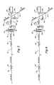
- FIGS. 1 and 2 there is shown a glass mounted antenna assembly 10 that is constructed in accordance with the present invention and useful as a mobile communications antenna assembly capable of being mounted on a vehicle and adapted for use over a selected band of frequencies in the VHF and UHF ranges.
- a primary antenna radiating element 12 is mounted on the exterior of a glass 14 and coupling and tuning circuit elements 16 are mounted on the interior surface of the glass 14. It is understood that although the invention is shown as being mounted on opposite sides of a glass pane, the antenna would function equally well if the material separating the elements were any other dielectric such as a plastic panel. Likewise, as will be described below and shown in FIGS. 5 and 6, the invention can be embodied in an antenna assembly that is capable of being mounted on a single side of a mounting surface that is either non-conductive or, with minor modification, conductive so as to provide a ground plane for the radiating elements of the antenna system.
- the invention is ideally suited for use with motor vehicles and can be used on the windshield, the back window, any glass or plastic panel, or any location that provides optimum operation.
- only the primary radiating element 12 is on the exterior of the vehicle.
- the remaining elements of assembly 10 are in the interior of the vehicle, where they can be directly connected to a transceiver through conventional transmission line means such as coaxial cable.
- the primary radiating element 12 contains first, second and third, collinear radiating sections, 18, 20 and 22, respectively.
- First and second collinear radiating sections 18 and 20 each have an electrical length substantially equal to five-eighths of the center wavelength of the selected frequency band. Sections 18 and 20 are separated and electrically connected to one another by a first phasing inductance coil 24. Coil 24 is adapted to maintain a predetermined phase relationship between electrical signals radiating from the first and second sections 18, 20, and is preferably a helical open air coil formed from the primary radiating element 12 itself.
- the third collinear radiating section 22 has an electrical length substantially equal to one-quarter of the center wavelength of the selected frequency band and is electrically connected at one end 26 to second collinear radiating section 20 by a second phasing inductance coil 28.
- Coil 28 is also adapted to maintain a predetermined phase relationship between electrical signals radiating from the second and third sections, 20 and 22 respectively.
- Coil 28 is also preferably protected by mounting and covering it with a portion 29 of the second radiating section 20.
- third section 22 can be covered with a layer 31 of insulating material so as to prevent shorting of the electrical signal between the second and third sections, thus providing for both a safer and more aesthetically pleasing final product capable of withstanding both environmental forces and mechanical stresses of vehicle movement.
- Third section 22 has a second opposite base end 30 that is adapted to mate with a mounting assembly better described below.
- Third collinear radiating section 22 further has a radiating surface 32 with an area that is substantially greater than the radiating surface areas of each of the first and second radiating sections 18 and 20.
- one preferred way of providing third collinear radiating section with an enlarged radiating surface 32 is to construct section 22 with a diameter substantially greater than the diameter of each of the first and second radiating sections 18 and 20. In this manner the radiating surface area 32 of third collinear radiating section 22 will be greater in comparison to the radiating surface areas of the first and second sections.
- a base assembly 34 is connected to the base end 30 of the third radiating section 22 to provide a mounting support for the radiating element 12.
- Base 34 preferably is user adjustable to permit radiating element 12 to be maintained generally vertical to the surface over which the vehicle is travelling. This user adjustment may be accomplished by having a the radiating element pivotally connected to base 34 and held in desired position by a set screw 48.
- the primary radiating element 12 can move, at base end 30 of its third radiating section, with respect to its connection to base assembly 34 by means of a set screw 56 that can be used to vary the exposed length of the radiating element 12 and to lock it at the optimum length.
- Base 34 has an electrically conductive plate member 36 attached thereto having a fixed surface area.
- Member 36 is electrically connected to and disposed adjacent base end 30 of third radiating section 22, for mounting radiating element 12 to a first, exterior side 14 of a non-conductive body portion, here shown to be the exterior portion 14 of a glass window of a vehicle.
- the base end 30 of third radiating section 22 is elevated above the surface of the glass window and, accordingly, of the surrounding body portion of the vehicle itself.
- a second electrically conductive coupling member 38 is mounted on a second, opposite side 40 of the non-conductive body portion (glass window) in substantial juxtaposition with first electrically conductive member 36 and defines with non-conductive body portion (glass window) intermediate these two members 36 and 38, a coupling capacitor having a fixed plate surface area at the base end 30 of the third radiating section and located adjacent a current node thereof.
- Impedance matching circuitry 42 which may include a tuned circuit, such as a series tuned circuit, that is selectively tunable to the nominal resonant frequency of the radiating element, is electrically connected to second electrically conductive coupling member 38 in the immediate proximity thereof to resonate in conjunction with radiating element 12.
- Impedance matching circuitry 42 preferably has an impedance which varies between a first impedance, measured at the connection to the second electrically conductive coupling member 38, substantially equal to the impedance at the base end 30 of third radiating section 22, and a second impedance at least several orders of magnitude less than the first impedance.
- impedance matching circuitry 42 would include a user adjustable capacitance member (as shown in FIGS. 3 through 6), so that minor adjustments can be made in the field to accommodate the antenna assembly to changes in its operating environment. Such changes can be occasioned by different thicknesses in the glass window through which the signal is transmitted or by a change in capacitance or impedance caused by a build up of pollutants on the antenna assembly itself.
- a coaxial fitting 44 connects a transmission line (not shown) to impedance matching circuitry 42 at a point where the impedance is substantially equal to the impedance of the transmission line.
- the transmission line is preferably a coaxial cable that connects antenna assembly 10 and a radio communications unit (not shown).
- the transmission line should have an impedance that is orders of magnitude less than the impedance of the antenna assembly 10 at base end 30 of the third radiating section thereof.
- first and second stub antennas 50 and 52 Extending at right angles to a line parallel to the axis of the primary radiating element 12, are first and second stub antennas 50 and 52 respectively. Each preferably has an effective wavelength of one-quarter of a wavelength.
- the stub antennas 50, 52 are mounted on an interior base member 54 which is adapted to be adhered to the inner surface 40 of the glass window.
- the interior and exterior mounted coupling members 36 and 38 are designed to be matched in alignment when mounted since each is intended to be one plate of a capacitor which uses the glass window itself as the dielectric element.
- FIG. 3 there is shown a preferred circuit for use with the antenna of the present invention.
- the primary antenna radiating element 12 is shown directly connected to one plate 100 of a capacitor 102, the other plate 104 of which is connected through a tuning circuit 106 to the signal lead 108 of a coaxial cable 110 that is coupled to a transceiver (not shown).
- the glass 112 to which the capacitor plates 100, 104 are adhered, is the dielectric for the capacitor 102.
- An adjustable tuning capacitor 114 is serially connected to the "inside" plate 104, and may, for circuit purposes, be considered a "lumped" capacitive element.
- a first inductor 116 serially couples the capacitors 102, 114 to the signal lead 108.
- a second inductor 118 couples the signal lead 108 to the ground or shield 120 of the coaxial cable 110.
- the stub antennas 122, 124 are connected to the grounded shield 120, as well.
- the circuit is connected to a transceiver and a standing wave ratio meter is used in conjunction with the adjustable tuning capacitor 114 to achieve peak performance in the 820 to 895 MHz frequency band which has been alloted to cellular mobile telephone system use.
- the total capacitance (of the dielectric panel and the adjustable tuning capacitor 114) functions to "cancel" the inductive reactance of the antenna.
- the inductors 116, 118 are selected to match the impedance of the antenna circuit to the coaxial cable 110. Accordingly, energy can be transferred through the glass or other dielectric panel with a minimum of energy loss.
- the grounded stub antennas 122, 124 act as a "mirror image" (ground plane) of the primary antenna radiating element 12. In the absence of the grounded stub antennas, a reflection current would appear at the coaxial cable 110 and a good impedance match would be difficult, if not impossible to achieve.
- FIG. 4 is an alternative circuit embodiment in which a second trimmer capacitor 126 is substituted for the second inductor 118 of FIG. 3.
- Other elements in FIG. 4 similar to those elements described above for FIG. 3, are shown as primed reference numerals corresponding to their unprimed counterparts in FIG. 3.
- the optimum frequency range for which it is tuned tends to be quite sharp and narrow. Accordingly, it is not as satisfactory when dealing with a relatively broad frequency band such as the approximately 75 MHz bandwidth available in the cellular telephone band. However, for those applications where the frequencies in use fall within a fairly narrow band, the alternative embodiment should prove satisfactory.
- FIGS. 5 and 6 there is shown in schematic form an alternative antenna system embodying the present invention generally employing stub antennas mounted on a single side of a non-conductive body portion of a vehicle along with the principal antenna element.
- a single base element is employed which can be fastened to virtually any surface and does not require an exterior and an interior mounted antenna assembly.
- FIGS. 5 and 6 are similar to FIGS. 3 and 4, respectively, and illustrate the general electrical connections of an antenna assembly embodying the present invention adapted for mounting to a single side of a non-conductive body portion of a vehicle. Similar parts retain the same reference numerals, the only difference being the absence of the capacitors 102, 102′.
- the antenna of the present invention is to be mounted on a body portion of a vehicle that is suitable as a reflective signal ground plane, then the stub antennas described above may be eliminated and the principal radiating element described above may be directly mounted to the desired location by any number of presently known mounting brackets.
Landscapes
- Details Of Aerials (AREA)
- Support Of Aerials (AREA)
Applications Claiming Priority (2)
| Application Number | Priority Date | Filing Date | Title |
|---|---|---|---|
| US07/202,123 US4857939A (en) | 1988-06-03 | 1988-06-03 | Mobile communications antenna |
| US202123 | 1988-06-03 |
Publications (2)
| Publication Number | Publication Date |
|---|---|
| EP0348054A2 true EP0348054A2 (de) | 1989-12-27 |
| EP0348054A3 EP0348054A3 (de) | 1990-08-08 |
Family
ID=22748586
Family Applications (1)
| Application Number | Title | Priority Date | Filing Date |
|---|---|---|---|
| EP89305569A Withdrawn EP0348054A3 (de) | 1988-06-03 | 1989-06-02 | Bewegliche Verbindungsantenne |
Country Status (5)
| Country | Link |
|---|---|
| US (1) | US4857939A (de) |
| EP (1) | EP0348054A3 (de) |
| JP (1) | JPH0236602A (de) |
| KR (1) | KR920002895B1 (de) |
| CA (1) | CA1322786C (de) |
Cited By (2)
| Publication number | Priority date | Publication date | Assignee | Title |
|---|---|---|---|---|
| WO1998048479A1 (en) * | 1997-04-23 | 1998-10-29 | Qualcomm Incorporated | A multi-frequency antenna |
| RU2447552C1 (ru) * | 2010-10-18 | 2012-04-10 | Российская Федерация, от имени которой выступает государственный заказчик - Государственная корпорация по атомной энергии "Росатом" | Планарный излучатель |
Families Citing this family (52)
| Publication number | Priority date | Publication date | Assignee | Title |
|---|---|---|---|---|
| USD310084S (en) | 1988-07-05 | 1990-08-21 | Alliance Research Corporation | Coupling block for a glass mounted antenna |
| US5023622A (en) * | 1989-07-13 | 1991-06-11 | Blaese Herbert R | On-glass antenna with center-fed dipole operation |
| DE8911355U1 (de) * | 1989-09-23 | 1989-12-14 | Robert Bosch Gmbh, 7000 Stuttgart | Stabförmige Funkgewinnantenne |
| DE3931807A1 (de) * | 1989-09-23 | 1991-04-04 | Bosch Gmbh Robert | Stabfoermige funkgewinnantenne |
| US5262795A (en) * | 1990-01-30 | 1993-11-16 | Cellular Ic, Inc. | Unitary cellular antenna system |
| US5181043A (en) * | 1990-05-22 | 1993-01-19 | Alliance Research Corporation | Passive repeater for cellular phones |
| JP2515624B2 (ja) * | 1990-11-01 | 1996-07-10 | 原田工業株式会社 | アンテナ結合回路 |
| USD332609S (en) | 1990-11-27 | 1993-01-19 | Alliance Research Corporation | Cellular antenna |
| US5283589A (en) * | 1992-02-05 | 1994-02-01 | Richard Hirschmann Of America, Inc. | Window mountable UHF mobile antenna system |
| USD346603S (en) | 1992-08-19 | 1994-05-03 | Poli-Auto, Inc. | Base for an imitation antenna |
| US5471222A (en) * | 1993-09-28 | 1995-11-28 | The Antenna Company | Ultrahigh frequency mobile antenna system using dielectric resonators for coupling RF signals from feed line to antenna |
| US5481271A (en) * | 1994-03-25 | 1996-01-02 | Harada Kogyo Kabushiki Kaisha | Two-wave antenna for telephones used in vehicles |
| US5742255A (en) * | 1994-07-12 | 1998-04-21 | Maxrad, Inc. | Aperture fed antenna assembly for coupling RF energy to a vertical radiator |
| US5451966A (en) * | 1994-09-23 | 1995-09-19 | The Antenna Company | Ultra-high frequency, slot coupled, low-cost antenna system |
| US5898408A (en) * | 1995-10-25 | 1999-04-27 | Larsen Electronics, Inc. | Window mounted mobile antenna system using annular ring aperture coupling |
| US6172651B1 (en) | 1995-10-25 | 2001-01-09 | Larsen Electronics, Inc. | Dual-band window mounted antenna system for mobile communications |
| KR100263034B1 (ko) * | 1995-12-02 | 2000-08-01 | 김지태 | 인텔리전트 금고 |
| US5821907A (en) * | 1996-03-05 | 1998-10-13 | Research In Motion Limited | Antenna for a radio telecommunications device |
| US6052088A (en) * | 1997-08-26 | 2000-04-18 | Centurion International, Inc. | Multi-band antenna |
| US6215451B1 (en) | 1997-11-17 | 2001-04-10 | Allen Telecom Inc. | Dual-band glass-mounted antenna |
| US6191747B1 (en) * | 1998-04-07 | 2001-02-20 | Hirschmann Electronics, Inc. | Dual band antenna |
| DE19939321A1 (de) * | 1999-08-19 | 2001-04-05 | Bosch Gmbh Robert | Kombinierte Stab- und Planarantenne |
| WO2001022528A1 (es) | 1999-09-20 | 2001-03-29 | Fractus, S.A. | Antenas multinivel |
| ATE248443T1 (de) | 1999-10-26 | 2003-09-15 | Fractus Sa | Ineinandergeschachtelte mehrbandgruppenantennen |
| US6369766B1 (en) * | 1999-12-14 | 2002-04-09 | Ems Technologies, Inc. | Omnidirectional antenna utilizing an asymmetrical bicone as a passive feed for a radiating element |
| BR0017065A (pt) * | 2000-01-19 | 2003-11-04 | Fractus Sa | Antena e conjunto de antenas de enchimento de espaço |
| EP2051325A1 (de) * | 2000-01-19 | 2009-04-22 | Fractus, S.A. | Fraktale und raumfüllende Übertragungsleiter, Resonatoren, Filter und passive Netzelemente |
| US6329951B1 (en) * | 2000-04-05 | 2001-12-11 | Research In Motion Limited | Electrically connected multi-feed antenna system |
| AU4121000A (en) * | 2000-04-19 | 2001-11-07 | Ficosa Internacional, S.A. | Multilevel advanced antenna for motor vehicles |
| US7511675B2 (en) * | 2000-10-26 | 2009-03-31 | Advanced Automotive Antennas, S.L. | Antenna system for a motor vehicle |
| JP2002204118A (ja) * | 2000-10-31 | 2002-07-19 | Mitsubishi Materials Corp | アンテナ |
| BR0116866A (pt) | 2001-02-07 | 2004-06-22 | Fractus Sa | Antena extra plana de banda larga miniatura |
| US6664930B2 (en) | 2001-04-12 | 2003-12-16 | Research In Motion Limited | Multiple-element antenna |
| DE60128837T2 (de) * | 2001-04-16 | 2008-02-28 | Fractus, S.A. | Doppelbandige dualpolarisierte gruppenantenne |
| US6608597B1 (en) | 2001-09-24 | 2003-08-19 | Allen Telecom, Inc. | Dual-band glass-mounted antenna |
| ATE385054T1 (de) * | 2001-10-16 | 2008-02-15 | Fractus Sa | Mehrfrequenz-mikrostreifen-patch-antenne mit parasitär gekoppelten elementen |
| CN100382385C (zh) | 2001-10-16 | 2008-04-16 | 弗拉克托斯股份有限公司 | 加载天线 |
| US9755314B2 (en) | 2001-10-16 | 2017-09-05 | Fractus S.A. | Loaded antenna |
| WO2003034544A1 (en) * | 2001-10-16 | 2003-04-24 | Fractus, S.A. | Multiband antenna |
| ES2190749B1 (es) | 2001-11-30 | 2004-06-16 | Fractus, S.A | Dispersores "chaff" multinivel y/o "space-filling", contra radar. |
| DE60329793D1 (de) * | 2002-06-21 | 2009-12-03 | Research In Motion Ltd | Mehrfachelement-Antenne mit Parasitärkoppler |
| CA2413360C (en) * | 2002-11-29 | 2008-09-16 | Research In Motion Limited | Combination of tube assembly and clip for wireless antenna grounding |
| US6791500B2 (en) | 2002-12-12 | 2004-09-14 | Research In Motion Limited | Antenna with near-field radiation control |
| US6812897B2 (en) | 2002-12-17 | 2004-11-02 | Research In Motion Limited | Dual mode antenna system for radio transceiver |
| JP2004318466A (ja) * | 2003-04-16 | 2004-11-11 | Matsushita Electric Ind Co Ltd | 商品券、商品券発行システム及び商品券利用システム |
| ATE375012T1 (de) * | 2003-05-14 | 2007-10-15 | Research In Motion Ltd | Mehrbandantenne mit streifenleiter- und schlitzstrukturen |
| DE60335674D1 (de) * | 2003-06-12 | 2011-02-17 | Research In Motion Ltd | Mehrelement-Antenne mit schwimmenden parasitären Antennenelement |
| US6980173B2 (en) * | 2003-07-24 | 2005-12-27 | Research In Motion Limited | Floating conductor pad for antenna performance stabilization and noise reduction |
| US7369089B2 (en) * | 2004-05-13 | 2008-05-06 | Research In Motion Limited | Antenna with multiple-band patch and slot structures |
| US8738103B2 (en) | 2006-07-18 | 2014-05-27 | Fractus, S.A. | Multiple-body-configuration multimedia and smartphone multifunction wireless devices |
| TWM318202U (en) * | 2007-01-10 | 2007-09-01 | Smart Ant Telecom Co Ltd | Omni-directional high-gain dipole antenna |
| CN110212315B (zh) * | 2018-02-28 | 2022-02-22 | 深圳市海能达通信有限公司 | 共线天线组件及串馈全向共线天线阵列 |
Family Cites Families (8)
| Publication number | Priority date | Publication date | Assignee | Title |
|---|---|---|---|---|
| US4238799A (en) * | 1978-03-27 | 1980-12-09 | Avanti Research & Development, Inc. | Windshield mounted half-wave communications antenna assembly |
| CA1223339A (en) * | 1983-09-23 | 1987-06-23 | James Hadzoglou | Cellular mobile communications antenna |
| US4674773A (en) * | 1984-01-23 | 1987-06-23 | Teleco Oilfield Services Inc. | Insulating coupling for drill collars and method of manufacture thereof |
| US4658259A (en) * | 1985-03-06 | 1987-04-14 | Blaese Herbert R | On-glass antenna |
| US4764773A (en) * | 1985-07-30 | 1988-08-16 | Larsen Electronics, Inc. | Mobile antenna and through-the-glass impedance matched feed system |
| US4675687A (en) * | 1986-01-22 | 1987-06-23 | General Motors Corporation | AM-FM cellular telephone multiband antenna for motor vehicle |
| US4794319A (en) * | 1986-07-03 | 1988-12-27 | Alliance Research Corporation | Glass mounted antenna |
| US4725846A (en) * | 1986-12-12 | 1988-02-16 | Western Mobile Communications, Inc. | Disguise antenna operating in the cellular band |
-
1988
- 1988-06-03 US US07/202,123 patent/US4857939A/en not_active Expired - Fee Related
-
1989
- 1989-06-02 CA CA000601606A patent/CA1322786C/en not_active Expired - Fee Related
- 1989-06-02 EP EP89305569A patent/EP0348054A3/de not_active Withdrawn
- 1989-06-03 JP JP1140267A patent/JPH0236602A/ja active Pending
- 1989-06-03 KR KR1019890007643A patent/KR920002895B1/ko not_active Expired
Cited By (4)
| Publication number | Priority date | Publication date | Assignee | Title |
|---|---|---|---|---|
| WO1998048479A1 (en) * | 1997-04-23 | 1998-10-29 | Qualcomm Incorporated | A multi-frequency antenna |
| US5926143A (en) * | 1997-04-23 | 1999-07-20 | Qualcomm Incorporated | Multi-frequency band rod antenna |
| AU736883B2 (en) * | 1997-04-23 | 2001-08-02 | Qualcomm Incorporated | A multi-frequency band rod antenna |
| RU2447552C1 (ru) * | 2010-10-18 | 2012-04-10 | Российская Федерация, от имени которой выступает государственный заказчик - Государственная корпорация по атомной энергии "Росатом" | Планарный излучатель |
Also Published As
| Publication number | Publication date |
|---|---|
| KR920002895B1 (ko) | 1992-04-06 |
| EP0348054A3 (de) | 1990-08-08 |
| CA1322786C (en) | 1993-10-05 |
| JPH0236602A (ja) | 1990-02-06 |
| US4857939A (en) | 1989-08-15 |
| KR900001055A (ko) | 1990-01-31 |
Similar Documents
| Publication | Publication Date | Title |
|---|---|---|
| US4857939A (en) | Mobile communications antenna | |
| US4794319A (en) | Glass mounted antenna | |
| CA1260608A (en) | Mobile antenna feed system | |
| US4847629A (en) | Retractable cellular antenna | |
| US4825217A (en) | Car phone antenna assembly | |
| US5734352A (en) | Multiband antenna system | |
| US4395713A (en) | Transit antenna | |
| US8576130B2 (en) | Wideband antenna | |
| US4238799A (en) | Windshield mounted half-wave communications antenna assembly | |
| US10811760B2 (en) | Multi-band window antenna | |
| KR100724300B1 (ko) | 하프 루프 안테나 | |
| US5283589A (en) | Window mountable UHF mobile antenna system | |
| US4940989A (en) | Apparatus and method for matching radiator and feedline impedances and for isolating the radiator from the feedline | |
| US5343214A (en) | Cellular mobile communications antenna | |
| US5610619A (en) | Backlite antenna for AM/FM automobile radio having broadband FM reception | |
| US6297711B1 (en) | Radio frequency multiplexer for coupling antennas to AM/FM/WB, CB/WB, and cellular telephone apparatus | |
| JPH0374846B2 (de) | ||
| US4460896A (en) | Antenna with tunable helical resonator | |
| US5790079A (en) | Backlite antenna for AM/FM automobile radio | |
| US5798736A (en) | Antenna system having a plurality of fundamental resonances | |
| JP3431379B2 (ja) | アンテナ | |
| JP3230841B2 (ja) | 可変長ホイップアンテナ | |
| US4349825A (en) | Antenna assembly for high frequency ranges | |
| GB2086662A (en) | Antenna systems | |
| KR920003563B1 (ko) | 유리창 설치 안테나 |
Legal Events
| Date | Code | Title | Description |
|---|---|---|---|
| PUAI | Public reference made under article 153(3) epc to a published international application that has entered the european phase |
Free format text: ORIGINAL CODE: 0009012 |
|
| AK | Designated contracting states |
Kind code of ref document: A2 Designated state(s): BE DE GB LU NL SE |
|
| PUAL | Search report despatched |
Free format text: ORIGINAL CODE: 0009013 |
|
| AK | Designated contracting states |
Kind code of ref document: A3 Designated state(s): BE DE GB LU NL SE |
|
| RAP3 | Party data changed (applicant data changed or rights of an application transferred) |
Owner name: ALLIANCE RESEARCH CORPORATION |
|
| 17P | Request for examination filed |
Effective date: 19901206 |
|
| 17Q | First examination report despatched |
Effective date: 19930312 |
|
| STAA | Information on the status of an ep patent application or granted ep patent |
Free format text: STATUS: THE APPLICATION IS DEEMED TO BE WITHDRAWN |
|
| 18D | Application deemed to be withdrawn |
Effective date: 19940713 |