EP0348036A2 - Frequenz-moduliertes Radargerät mit schmaler Bandbreite für die Hindernisermittlung - Google Patents
Frequenz-moduliertes Radargerät mit schmaler Bandbreite für die Hindernisermittlung Download PDFInfo
- Publication number
- EP0348036A2 EP0348036A2 EP89304801A EP89304801A EP0348036A2 EP 0348036 A2 EP0348036 A2 EP 0348036A2 EP 89304801 A EP89304801 A EP 89304801A EP 89304801 A EP89304801 A EP 89304801A EP 0348036 A2 EP0348036 A2 EP 0348036A2
- Authority
- EP
- European Patent Office
- Prior art keywords
- signal
- frequency
- coefficient
- range
- value
- Prior art date
- Legal status (The legal status is an assumption and is not a legal conclusion. Google has not performed a legal analysis and makes no representation as to the accuracy of the status listed.)
- Granted
Links
Images


Classifications
-
- G—PHYSICS
- G01—MEASURING; TESTING
- G01S—RADIO DIRECTION-FINDING; RADIO NAVIGATION; DETERMINING DISTANCE OR VELOCITY BY USE OF RADIO WAVES; LOCATING OR PRESENCE-DETECTING BY USE OF THE REFLECTION OR RERADIATION OF RADIO WAVES; ANALOGOUS ARRANGEMENTS USING OTHER WAVES
- G01S13/00—Systems using the reflection or reradiation of radio waves, e.g. radar systems; Analogous systems using reflection or reradiation of waves whose nature or wavelength is irrelevant or unspecified
- G01S13/88—Radar or analogous systems specially adapted for specific applications
- G01S13/93—Radar or analogous systems specially adapted for specific applications for anti-collision purposes
- G01S13/931—Radar or analogous systems specially adapted for specific applications for anti-collision purposes of land vehicles
-
- G—PHYSICS
- G01—MEASURING; TESTING
- G01S—RADIO DIRECTION-FINDING; RADIO NAVIGATION; DETERMINING DISTANCE OR VELOCITY BY USE OF RADIO WAVES; LOCATING OR PRESENCE-DETECTING BY USE OF THE REFLECTION OR RERADIATION OF RADIO WAVES; ANALOGOUS ARRANGEMENTS USING OTHER WAVES
- G01S13/00—Systems using the reflection or reradiation of radio waves, e.g. radar systems; Analogous systems using reflection or reradiation of waves whose nature or wavelength is irrelevant or unspecified
- G01S13/02—Systems using reflection of radio waves, e.g. primary radar systems; Analogous systems
- G01S13/06—Systems determining position data of a target
- G01S13/08—Systems for measuring distance only
- G01S13/32—Systems for measuring distance only using transmission of continuous waves, whether amplitude-, frequency-, or phase-modulated, or unmodulated
- G01S13/34—Systems for measuring distance only using transmission of continuous waves, whether amplitude-, frequency-, or phase-modulated, or unmodulated using transmission of continuous, frequency-modulated waves while heterodyning the received signal, or a signal derived therefrom, with a locally-generated signal related to the contemporaneously transmitted signal
- G01S13/343—Systems for measuring distance only using transmission of continuous waves, whether amplitude-, frequency-, or phase-modulated, or unmodulated using transmission of continuous, frequency-modulated waves while heterodyning the received signal, or a signal derived therefrom, with a locally-generated signal related to the contemporaneously transmitted signal using sawtooth modulation
-
- G—PHYSICS
- G01—MEASURING; TESTING
- G01S—RADIO DIRECTION-FINDING; RADIO NAVIGATION; DETERMINING DISTANCE OR VELOCITY BY USE OF RADIO WAVES; LOCATING OR PRESENCE-DETECTING BY USE OF THE REFLECTION OR RERADIATION OF RADIO WAVES; ANALOGOUS ARRANGEMENTS USING OTHER WAVES
- G01S13/00—Systems using the reflection or reradiation of radio waves, e.g. radar systems; Analogous systems using reflection or reradiation of waves whose nature or wavelength is irrelevant or unspecified
- G01S13/003—Bistatic radar systems; Multistatic radar systems
-
- G—PHYSICS
- G01—MEASURING; TESTING
- G01S—RADIO DIRECTION-FINDING; RADIO NAVIGATION; DETERMINING DISTANCE OR VELOCITY BY USE OF RADIO WAVES; LOCATING OR PRESENCE-DETECTING BY USE OF THE REFLECTION OR RERADIATION OF RADIO WAVES; ANALOGOUS ARRANGEMENTS USING OTHER WAVES
- G01S13/00—Systems using the reflection or reradiation of radio waves, e.g. radar systems; Analogous systems using reflection or reradiation of waves whose nature or wavelength is irrelevant or unspecified
- G01S13/88—Radar or analogous systems specially adapted for specific applications
- G01S13/93—Radar or analogous systems specially adapted for specific applications for anti-collision purposes
- G01S13/931—Radar or analogous systems specially adapted for specific applications for anti-collision purposes of land vehicles
- G01S2013/9315—Monitoring blind spots
-
- G—PHYSICS
- G01—MEASURING; TESTING
- G01S—RADIO DIRECTION-FINDING; RADIO NAVIGATION; DETERMINING DISTANCE OR VELOCITY BY USE OF RADIO WAVES; LOCATING OR PRESENCE-DETECTING BY USE OF THE REFLECTION OR RERADIATION OF RADIO WAVES; ANALOGOUS ARRANGEMENTS USING OTHER WAVES
- G01S13/00—Systems using the reflection or reradiation of radio waves, e.g. radar systems; Analogous systems using reflection or reradiation of waves whose nature or wavelength is irrelevant or unspecified
- G01S13/88—Radar or analogous systems specially adapted for specific applications
- G01S13/93—Radar or analogous systems specially adapted for specific applications for anti-collision purposes
- G01S13/931—Radar or analogous systems specially adapted for specific applications for anti-collision purposes of land vehicles
- G01S2013/9317—Driving backwards
-
- G—PHYSICS
- G01—MEASURING; TESTING
- G01S—RADIO DIRECTION-FINDING; RADIO NAVIGATION; DETERMINING DISTANCE OR VELOCITY BY USE OF RADIO WAVES; LOCATING OR PRESENCE-DETECTING BY USE OF THE REFLECTION OR RERADIATION OF RADIO WAVES; ANALOGOUS ARRANGEMENTS USING OTHER WAVES
- G01S13/00—Systems using the reflection or reradiation of radio waves, e.g. radar systems; Analogous systems using reflection or reradiation of waves whose nature or wavelength is irrelevant or unspecified
- G01S13/88—Radar or analogous systems specially adapted for specific applications
- G01S13/93—Radar or analogous systems specially adapted for specific applications for anti-collision purposes
- G01S13/931—Radar or analogous systems specially adapted for specific applications for anti-collision purposes of land vehicles
- G01S2013/9323—Alternative operation using light waves
Definitions
- This invention relates to obstacle detection apparatus and more particularly to a narrow bandwidth frequency modulated continuous wave radar apparatus for detecting nearby objects.
- Obstacle detection apparatus for providing an indication of the distance and/or warning of nearby objects have been proposed.
- One application for such apparatus is for detecting objects in proximity to an automotive vehicle.
- the vehicle may employ a near obstacle detection apparatus to alert the vehicle operator of the presence of obstacles behind the vehicle while backing the vehicle, to alert the vehicle operator of any obstacle in front of the vehicle below the operator's line of sight or to alert the operator of approaching vehicles in areas that are out of the view of the rear and side view mirrors.
- Characteristics that are desirable in near obstacle detection apparatus include: (a) the ability to warn of obstacles having no motion relative to the detection apparatus, (b) the ability to detect the closest of multiple objects, (c) the ability to provide a measure of distance to the object even at very close distances, and (d) the ability to operate in all environmental conditions.
- One such apparatus is based on the Doppler signal resulting from relative motion between the apparatus and the object. As applied to a vehicle, this means that the apparatus could not warn the driver of a passive obstacle behind the vehicle until the vehicle operator has initiated backward movement.
- Ultrasonic and infrared near obstacle detection apparatus have also been proposed.
- Ultrasonic apparatus may be sensitive to wind noise and other ultrasonic noise sources and are constrained by the speed of sound while infrared apparatus suffer from back scattering caused from hydrometers and aerosols, sensitivity to object colour and from contamination of the optical surfaces.
- a frequency modulated continuous wave (FMCW) microwave radar apparatus has all of the above listed desirable characteristics.
- present FMCW near obstacle detection apparatus as, for example, disclosed in US Patent Nos. 3182323, 3893114, and 4620192, require a large radio frequency (RF) bandwidth in order to sense the range of objects very close to the radar apparatus.
- RF radio frequency
- a bandwidth of 500 MHz is required to sense an object at a range of 0.3 m, which is also the range resolution of the apparatus. It would be desirable to decrease the bandwidth of an FMCW near obstacle detection apparatus and thereby retain the desirable characteristics of such apparatus without increasing the minimum detection range of the apparatus.
- a narrow bandwidth frequency modulated radar apparatus (hereinafter referred to as radar apparatus), and a method of operation thereof, in accordance with the present invention are characterised by the features specified in the characterising portins of claims 1 and 9 respectively.
- a radar apparatus having a reduced RF bandwidth is employed for sensing nearby objects.
- the RF bandwidth of the radar apparatus is reduced to one-half the bandwidth normally required for an FMCW radar apparatus for a given desired minimum detection range.
- an RF signal is transmitted at a frequency modulated by a sawtooth signal.
- the transmitted RF signal is mixed with a signal returned from an object to generate an intermediate frequency (IF) signal having a frequency equal to the difference between the frequencies of the transmitted and returned RF signals, the IF signal frequency being a measure of the range to the object.
- IF intermediate frequency
- the difference between the low and high frequencies of the transmitted modulated RF signal comprises the RF bandwidth of the radar apparatus. This difference establishes the minimum range resolution for the (FMCW) radar apparatus.
- the generated IF signal is analyzed into a Fourier series.
- the coefficients of the Fourier series include the coefficient representing the DC component of the IF signal and the coefficients representing the harmonics of the IF signal.
- the range of the object when equal to or greater than L is determined by the Fourier coefficients representing the harmonic frequencies.
- This invention provides for the measurement of distances less than L/2 based on the relationship of the DC component of the IF signal represented by the DC coefficient of the Fourier series and the harmonics of the IF signal represented by the harmonic coefficients of the Fourier series.
- the radar apparatus may be used to detect objects at shorter ranges for a given RF bandwidth or the RF bandwidth of the radar apparatus may be reduced.
- the narrow bandwidth frequency modulated radar apparatus for obstacle detection (hereinafter referred to as radar apparatus) of this invention is illustrated in Figure 1 as applied to an automotive vehicle 10 for sensing an object 12 located at a distance D from the rear of the automotive vehicle.
- the radar apparatus in this embodiment provides a signal (audio, visual or both) having a frequency indicating the distance D of the object 12 behind the automotive vehicie 10. It is, of course, understood that the radar apparatus may be used to detect objects 12 in proximity to the automotive vehicle 10 other than rearward, such as for detecting objects that are out of the view of the vehicle rear view mirrors.
- the radar apparatus utilized in the automotive vehicle 10 of Figure 1 is, as previously described, a frequency modulated continuous wave radar apparatus.
- the transmitted signal is frequency modulated so that the frequency of an echo signal reflected from an object will be delayed from the frequency of the transmitted signal at any instant in time due to the round trip distance between the radar apparatus and the object. This difference in frequency permits a measurement of the range to the target.
- the frequency of the transmitted signal is made to increase linearly with time as indicated by the solid line. As depicted in this figure, the frequency changes from a frequency f1 to a frequency f2 over a time period T.
- the modulation rate of the transmitted signal is therefore (f2 - f1)/T. If an object is located at a distance D from the radar apparatus, the total round trip delay time for the signal is equal to 2 ⁇ where ⁇ equals D/C and where C is the speed of light.
- the resulting received signal is illustrated in Figure 2 as the dotted line shifted in time from the transmitted signal by the time 2 ⁇ .
- the instantaneous frequency deviation between the transmitted signal and the received signal is 2(f2 - f1) ⁇ /T.
- This difference frequency is commonly known as the intermediate frequency (IF) at the output of the radar apparatus mixer as will be described.
- IF intermediate frequency
- the number of cycles in the IF signal at the mixer output is 2(f2 - f1) ⁇ .
- the frequency of the IF signal is the harmonic frequency ⁇ m which is a measure of the distance to the object, the distance being equal to mL where L is the range resolution of the radar apparatus dictated by the RF bandwidth as previously described.
- C n will have a finite value for all integers n.
- the Fourier coefficients will be examined to determine the frequency of the IF signal and accordingly the range to the object.
- the first harmonic frequency coefficient C n that exceeds a predetermined value in a constant amplitude controlled IF signal represents an object at a range of nL.
- the above description provides for the measurement of the distance D to the object 12 of Fig. 1 by measurement of the frequency of the IF signal as represented by the Fourier coefficients when the distance D is greater than or equal to the distance L which is the range resolution determined by the RF bandwidth.
- the present invention provides for sensing the object 12 at distances D equal to or less than L/2 based on the DC component of the IF signal represented by the DC coefficient C O of the Fourier series and its relationship to the harmonic frequency components of the IF signal represented by the harmonic frequency components C n of the Fourier series.
- the present invention recognizes that the distance to the object is less than L/2 if the DC coefficient C O is greater than a predetermined value which may be a constant in one embodiment or a value greater than any of the other coefficients C n associated with harmonics of the IF signal in another embodiment.
- the presence of a DC coefficient whose magnitude exceeds that of the remaining Fourier coefficients indicates that an object is located at a range closer than L/2 from the receiver.
- the ability to detect ranges less than L/2 permits the radar apparatus operating bandwidth to be reduced by a factor of 2 while yet maintaining the capability of detecting objects within the desired minimum distance. For example, as previously indicated, a frequency bandwidth of 500 MHz was required in order to detect an object at 0.3 m from the radar apparatus. However, by utilizing the aforementioned relationship of the DC coefficient of the Fourier series and the remaining Fourier coefficients, the bandwidth may be reduced to 250 MHz. While the range resolution decreases (increased spacing), the minimum range using the DC component of the IF signal remains at 0.3 m.
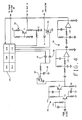
- a voltage controlled oscillator (VCO) 14 is modulated by a triangular waveform generated by an FM ramp generator 16 under control of a radar computer (computing means) 18.
- VCO voltage controlled oscillator
- the FM ramp generator 16 is controlled to provide a 1 millisecond ramp to the voltage controlled oscillator 14 to linearly sweep the frequency output of the voltage controlled oscillator 14 by a total of 250 MHz. This frequency deviation provides a range resolution of 0.6m.
- This FM ramp generator 16 includes a capacitor C1 whose charge is controlled in the specific example to provide the 1 millisecond ramp signal at 1.5 millisecond intervals.
- the capacitor C1 is held in a discharge condition by the radar computer 18.
- the radar computer 18 opens the circuit input to the FM ramp generator 16 to allow the capacitor C1 to be charged via the transistor T1 to provide a linearly increasing ramp voltage to the voltage controlled oscillator 14.
- the radar computer 18 again provides a ground signal to discharge the capacitor C1 and terminate the ramp signal. This cycle is repeated at 1.5 millisecond intervals.
- the frequency modulated output of the voltage controlled oscillator 14 is provided to a transmitting antenna 19 (transmitting means) which transmits the FMCW radar signal rearward from the automotive vehicle 10. If an object, such as the object 12, is present behind the automotive vehicle 10, the transmitted signal is reflected and received by a receiving antenna (receiving means) 20. The received RF signal is coupled from the receiving antenna 20 to an RF input of a mixer (mixing means) 22.
- a local oscillator signal LO is provided to the mixer 22 from the output of the voltage controlled oscillator 14 via a coupler 26 and a bistate phase shifter 28 having alternating 0 degree and 90 degree phase states as controlled by the radar computer 18.
- the radar computer 18 alternately shifts the phase state of the bistate phase shifter 28 with each ramp signal provided by the FM ramp generator 16.
- the resulting 0 and 90 degree phase states of the bistate phase shifter 28 will allow the evaluation of the DC coefficient C O of the Fourier series which equals the square root of the sum of the squares of A O and B O , where A O is the DC component of the IF output of the mixer 22 when the phase shifter is set at zero degrees while B O is the DC component of the IF output when the phase shifter is set at 90 degrees.
- the bistate phase shifter 28 is equivalent to using two mixers in quadrature. This arrangement assures the detection of an obstacle at a very close range avoiding misdetection when the local oscillator signal LO and the RF signal received from the object 12 are exactly 90 degrees out of phase.
- the IF signal output of the mixer 22 is provided to a low noise amplifier 30 which includes transistors T2 and T3 and associated circuitry that includes a capacitor C2 that helps reduce clutter by reducing the gain of the low noise amplifier at decreasing ranges to an obstacle.
- the radar computer 18 provides for automatic gain control of the low noise amplifier 30 by controlling the impedance of a field effect transistor 32 parallel coupled with a resistor R1 in the collector circuit of the transistor T3.
- the impedance of the field effect transistor 32 for controlling the gain of the low noise amplifier 30 is adjusted by the radar computer 18 to maintain a substantially constant peak-to-peak amplitude of the IF signal. This is accomplished by controlling the charge of a capacitor 36 connected to the gate of the field effect transistor 32.
- the capacitor 36 is discharged by the radar computer 18 through a diode 38 which has a high voltage normally applied to its cathode and charged by the radar computer through a diode 40 whose anode is normally grounded by the computer.
- the radar computer 18 determines the peak-to-peak value of the IF signal and adjusts the impedance of the field effect transistor 32 by incrementally charging or discharging the capacitor 36 via diodes 38 or 40 in direction to control the gain of the low noise amplifier 30 to maintain the desired constant peak-to-peak IF signal.
- the gain controlled signal from the low noise amplifier 30 is provided to a band pass filter 34 whose output comprises the IF signal input to the radar computer 18.
- the band pass filter 34 is a 1 to 8 KHz band pass filter with additional gain.
- the band pass filter circuit illustrated in Figure 4 provides for a 2 pole rolloff at 1 KHz and a 4 pole rolloff at 8 KHZ.
- the IF signal output of the band pass filter 34 is supplied to the radar computer 18 which analyzes the signal to determine the range to an object 12 rearward of the automotive vehicle 10.
- the radar computer 18 samples the IF signal at 32 points during the period of the ramp provided by the FM ramp generator 16.
- a 32 point discrete Fourier transform is performed to evaluate the DC and harmonic levels of the IF signal. From the DC and harmonic levels, the range to the object 12 from the rear of the automotive vehicle 10 is determined.
- the FM ramp generator 16 provides for the 250 megahertz sweep over a period of 1 millisecond
- the DC component of the Fourier series provides for detection of obstacles at ranges less than 0.3m.
- the lowest ordered harmonic, 1 KHz represents a range of 0.6m and each successive higher ordered 1 KHz harmonic represents an additional range of 0.6m.
- the resolution of the radar apparatus is 0.6m dictated by the 250 MHz sweep of the transmitted signal and the DC component of the IF signal is effective to provide an indication of an object within a range of 0.3m from the radar apparatus.
- the radar computer 18 provides an output to an indicator via an output driver transistor 42 for indicating the presence of an object 12 behind the automotive vehicle 10 and the range D to the object.
- the indicator may be a visual or audible indicator or both.
- the signal provided to the indicator takes the form of a variable frequency, square wave signal. In general, the period of the signal is proportional to range to the object 12 so that as the object becomes closer to the automotive vehicle, the frequency of the signal is increased exponentially. Other forms of indicators may be employed including a display providing a numerical indication of range.
- the radar computer 18 takes the form of a standard digital computer.
- the radar computer 18 may include a Motorola 68HC11 microprocessor along with a power supply generating the required voltages.
- the radar computer 18 includes a central processing unit (CPU) which executes an operating program permanently stored in a read only memory (ROM) which also stores tables and constants utilized in the determination of range and for controlling the various functions previously described. Contained within the CPU are the conventional counters, registers, accumulators, etc., along with a clock which provides a high frequency clock signal.
- the radar computer 18 also includes a random access memory (RAM) into which data may be temporarily stored and from which data may be read at various address locations determined in accordance with the program stored in the ROM.
- a power control unit (PCU) receives battery voltage and provides regulated power to the various operating circuits of the radar apparatus.
- the radar computer 18 further includes an input/output circuit (I/O) that includes conventional discrete and timer output sections.
- An analogue-to-digital unit (ADU) is included which provides for the measurement of the IF signal output of the band pass filter 34.
- the IF signal amplitude is sampled and converted under control of the CPU and stored in ROM designated RAM memory locations.
- the routine illustrated is executed once each 1.5 milliseconds as established by an internal timer counting clock pulses.
- the program proceeds to a step 44 where the FM ramp generator 16 is enabled to begin the voltage ramp by opening the circuit to the capacitor C1 of Figure 4.
- a series of steps are then executed to obtain 32 samples of the IF signal value at 32 microsecond intervals. In other embodiments, more or less samples may be taken. These steps begin at step 46 where the value of the IF signal output of the mixer 22 is sampled and stored.
- the value i of a counter register is compared to a value K representing the desired number of samples of the IF signal for each ramp output of the FM ramp generator 16 (equal to 32 in the present example). If i is not equal to K, i is incremented at step 50.
- the program waits for a time T1 until time for the next sampling of the IF signal.
- T i is 32 microseconds. With this interval, the 32 samples of the IF signal will take approximately 1 millisecond of time which is equal to the desired period of the ramp signal output of the FM ramp generator 16.
- the program repeats the steps 46 through 52. This sequence is repeated until such time that K samples of the IF signal have been taken.
- the program proceeds from decision step 48 to a step 54 where i is reset.
- the 32 samples of the IF signal at 32 microsecond intervals comprises the desired duration of the modulation of the transmitted RF signal. Accordingly at step 56 the ramp output of the FM ramp generator 16 is reset by applying a ground signal to the capacitor C1 which is discharged. As viewed in Figure 2, this results in the output of the voltage controlled oscillator 14 being returned to the frequency f1.
- the program determines the difference between the minimum and maximum values of the sampled IF values. If it is determined that the difference deviates from the desired peak-to-peak value of the IF signal, the radar computer 18 applies either a ground pulse to the diode 40 to incrementally discharge the capacitor 36 or a positive voltage pulse to the diode 38 to incrementally charge the capacitor 36 depending upon the sense of the required change in the gain of the low noise amplifier 30. The duration of the pulse is proportional to the gain error.
- the gain control pulse is provided immediately at the termination of the ramp output of the FM ramp generator 16 so as to allow time for the radar apparatus to settle prior to the generation of the next frequency modulated radar signal. If the difference in the minimum and maximum sampled values of the IF signal represents the desired peak-to-peak amplitude, the radar computer 18 does not issue a charge or discharge pulse to the capacitor 36.
- step 60 the bistate phase shifter 28 is toggled. This toggling shifts the output of the bistate phase shifter 28 between 0 and 90 degrees phase shift so as to enable the determination of the DC coefficient C0 of the Fourier series.
- the determination of the value of the DC coefficient C0 from the value of A0 of the Fourier series when the phase shifter output is set at 0 degrees and from B0 when the phase shifter output is set at 90 degrees avoids a potential misdetection when the local oscillator signal LO provided to the mixer 22 and the RF signal received from the object 12 are exactly 90 degrees out of phase. If the bistate phase shifter 28 last provided a 0 degree phase shift to the local oscillator signal, it will provide a 90 degree phase shift during the next execution of the routine of Figure 5.
- the program first executes the Fourier transform equations to determine the values of the coefficients A n , B n and A0 or B0 (depending on the phase of the local oscillator signal LO provided by the bistate phase shifter 28). Step 62 then determines the DC coefficient C o from the values of A0 and B0 determined during the last two executions of the 1.5 millisecond interrupt routine of Figure 5 and determines the harmonic frequency coefficients C n from the last determined values of A n and B n .
- the transform equations executed at step 62 are standard. In the present embodiment, step 62 executes discrete Fourier transform equations to determine the DC and frequency coefficients.
- the value of the DC coefficient C0 is compared with a calibration threshold. If the DC coefficient is greater than a calibration constant A indicating a range to the obstacle less than L/2 (0.3 m in the present example), the program proceeds to a step 66 to set the range equal to L/2. On the other hand, if the value of the DC coefficient C0 is less than A, the program proceeds to a step 68 where the first frequency coefficient C n that exceeds the constant A is identified. This identified harmonic frequency is a measure of the range to the object 12. For example, if the coefficient C1 (associated with the lowest ordered harmonic 1 KHz in the present example) is greater than A, the range to the object 12 is 0.6m. Similarly, if the first coefficient greater than A is C4 associated with the harmonic frequency 4 KHz, the range to the object 12 is 2.4m.
- the value of A is variable and set equal to the largest value of the harmonic frequency coefficients C n . In yet another embodiment, the value of A is set equal to the weighted sum of more than one of the harmonic coefficients.
- the sensed range to the obstacle is set equal to nL where n is the harmonic identified at step 68 and L is the minimum resolution determined by the frequency bandwidth of the transmitted RF signal (0.6m in this example).
- steps 68 and 70 provide for an indication of the range to the object 12 in 0.6m increments up to 5 meters corresponding to the 8th harmonic frequency cutoff of the band pass filter 34.
- the program next executes a series of steps to provide for limiting the change in the indicated range until the range reading has been determined to be in the same range bin for a predetermined consecutive number of range readings.
- this number may be seven.
- the program determines whether the new range determined at step 66 or 70 is the same as the range determined during the previous execution of the interrupt routine. If the range is equal to the old range, a number B stored in a register is incremented at step 74. This number is then compared at decision step 76 with a predetermined constant C such as seven.
- the program proceeds to a step 78 where B is reset to zero.
- the program proceeds from decision step 76 to a step 80 where the period of the signal for energizing the indicator is set as a function of the last sensed range.
- a number establishing the period of a square wave signal is set proportional to the detected range to the object 12 so that as the range decreases the frequency of the signal provided to the vehicle operator via the visual or audible indicator increases exponentially.
- the number set at step 80 may provide an indication to the vehicle operator via the audible or visual indicator having a one second period for a detected range of 5m to the object 12 decreasing to a period of 100 milliseconds for a detected range of 0.3m.
- step 82 a period count timing the period of the signal provided to the indicator is incremented.
- decision step 84 the value of the period count is compared to the period last set at step 80. If the set period has not expired, the program exits the interrupt routine. However, if the period has expired, the output to the indicator is toggled at step 86 and the period count is reset.
- the function of the steps 82 through 86 is to provide for the square wave output having a period determined by step 80 which in turn is established by the sensed range to the object 12. Accordingly, the operator is provided a visual or audible indication of the magnitude of the range to the object.
Landscapes
- Engineering & Computer Science (AREA)
- Radar, Positioning & Navigation (AREA)
- Remote Sensing (AREA)
- Physics & Mathematics (AREA)
- Computer Networks & Wireless Communication (AREA)
- General Physics & Mathematics (AREA)
- Electromagnetism (AREA)
- Radar Systems Or Details Thereof (AREA)
Applications Claiming Priority (2)
| Application Number | Priority Date | Filing Date | Title |
|---|---|---|---|
| US07/209,111 US4901083A (en) | 1988-06-20 | 1988-06-20 | Near obstacle detection system |
| US209111 | 1988-06-20 |
Publications (3)
| Publication Number | Publication Date |
|---|---|
| EP0348036A2 true EP0348036A2 (de) | 1989-12-27 |
| EP0348036A3 EP0348036A3 (de) | 1991-03-27 |
| EP0348036B1 EP0348036B1 (de) | 1994-08-03 |
Family
ID=22777373
Family Applications (1)
| Application Number | Title | Priority Date | Filing Date |
|---|---|---|---|
| EP89304801A Expired - Lifetime EP0348036B1 (de) | 1988-06-20 | 1989-05-11 | Frequenz-moduliertes Radargerät mit schmaler Bandbreite für die Hindernisermittlung |
Country Status (6)
| Country | Link |
|---|---|
| US (1) | US4901083A (de) |
| EP (1) | EP0348036B1 (de) |
| JP (1) | JP2522547B2 (de) |
| CA (1) | CA1338479C (de) |
| DE (1) | DE68917222T2 (de) |
| ES (1) | ES2057117T3 (de) |
Cited By (6)
| Publication number | Priority date | Publication date | Assignee | Title |
|---|---|---|---|---|
| EP0535780A1 (de) * | 1991-09-30 | 1993-04-07 | Trw Inc. | Kompakter, flexibler und integrierter Millimeterwellenradarsensor |
| EP1239299A3 (de) * | 2001-03-06 | 2003-03-05 | Murata Manufacturing Co., Ltd. | FMCW-Radarempfänger mit frequenzabhängiger Verstärkung |
| EP1127755A3 (de) * | 2000-02-25 | 2004-04-28 | Delphi Technologies, Inc. | Antidiebstahlsicherung und Sicherungssystem |
| EP0974851B1 (de) * | 1998-07-23 | 2005-05-11 | Eaton VORAD Technologies, L.L.C. | Verfahren und Vorrichtung zur Regen-Clutter-Beseitigung für eine Radarsystem |
| ITTO20090251A1 (it) * | 2009-04-01 | 2010-10-02 | Elsag Datamat Spa | Sensore di prossimita' per area di parcheggio |
| EP2293099A1 (de) * | 2009-09-07 | 2011-03-09 | Alps Electric Co., Ltd. | Drahtlose Sensorvorrichtung |
Families Citing this family (44)
| Publication number | Priority date | Publication date | Assignee | Title |
|---|---|---|---|---|
| US5087918A (en) * | 1990-04-02 | 1992-02-11 | Delco Electronics Corporation | FMCW/2FD implementation for vehicle near obstacle detection system |
| US5134411A (en) * | 1990-07-13 | 1992-07-28 | General Microwave Corporation | Near range obstacle detection and ranging aid |
| CA2222637C (en) * | 1990-07-13 | 1999-12-14 | Zdenek Adler | Monostatic radar system having a one-port impedance matching device |
| JP2981312B2 (ja) * | 1991-08-08 | 1999-11-22 | 富士通株式会社 | Fm−cwレーダ装置 |
| JP2657020B2 (ja) * | 1992-03-17 | 1997-09-24 | 富士通株式会社 | Fm−cwレーダ装置 |
| US5280288A (en) * | 1992-08-14 | 1994-01-18 | Vorad Safety Systems, Inc. | Interference avoidance system for vehicular radar system |
| DE4242700C2 (de) * | 1992-12-17 | 2003-01-30 | Bosch Gmbh Robert | Verfahren zur Messung des Abstandes und der Geschwindigkeit von Objekten |
| US5633642A (en) * | 1993-11-23 | 1997-05-27 | Siemens Aktiengesellschaft | Radar method and device for carrying out the method |
| US5600253A (en) * | 1995-05-08 | 1997-02-04 | Eaton Corporation At Eaton Center | Electromagnetic wave reflective type, low cost, active proximity sensor for harsh environments |
| US5905380A (en) * | 1995-05-08 | 1999-05-18 | Eaton Corporation | Electromagnetic wave, reflective type, low cost, active proximity sensor for harsh environments |
| DE19529180C1 (de) * | 1995-08-08 | 1997-04-03 | Siemens Ag | Schaltungsanordnung mit einem Radargerät zur Ermittlung eines Abstandes oder einer Relativgeschwindigkeit |
| DE19538309C2 (de) * | 1995-10-14 | 1998-10-15 | Volkswagen Ag | Radarverfahren zur Messung von Abständen und Relativgeschwindigkeiten zwischen einem Fahrzeug und einem oder mehreren Hindernissen |
| US5914683A (en) * | 1996-09-12 | 1999-06-22 | O'conner; Joe S. | Ultra high resolution ranging unit |
| KR100852810B1 (ko) * | 2000-08-16 | 2008-08-18 | 레이던 컴퍼니 | 차량 레이더 시스템들과 기술들 |
| US6577269B2 (en) * | 2000-08-16 | 2003-06-10 | Raytheon Company | Radar detection method and apparatus |
| AU2001288273A1 (en) * | 2000-08-16 | 2002-02-25 | Raytheon Company | Video amplifier for a radar receiver |
| AU2001284953A1 (en) * | 2000-08-16 | 2002-02-25 | Raytheon Company | Safe distance algorithm for adaptive cruise control |
| US6492949B1 (en) * | 2000-08-16 | 2002-12-10 | Raytheon Company | Slot antenna element for an array antenna |
| US20020075138A1 (en) * | 2000-08-16 | 2002-06-20 | Van Rees H. Barteld | Portable object detection system |
| US6784828B2 (en) * | 2000-08-16 | 2004-08-31 | Raytheon Company | Near object detection system |
| JP2004508627A (ja) * | 2000-09-08 | 2004-03-18 | レイセオン・カンパニー | 経路予測システムおよび方法 |
| US6489917B2 (en) | 2000-11-30 | 2002-12-03 | Georgia Tech Research Corporation | Phase-based sensing system |
| US6708100B2 (en) * | 2001-03-14 | 2004-03-16 | Raytheon Company | Safe distance algorithm for adaptive cruise control |
| US7183995B2 (en) | 2001-08-16 | 2007-02-27 | Raytheon Company | Antenna configurations for reduced radar complexity |
| US6970142B1 (en) | 2001-08-16 | 2005-11-29 | Raytheon Company | Antenna configurations for reduced radar complexity |
| US6995730B2 (en) * | 2001-08-16 | 2006-02-07 | Raytheon Company | Antenna configurations for reduced radar complexity |
| US6611227B1 (en) | 2002-08-08 | 2003-08-26 | Raytheon Company | Automotive side object detection sensor blockage detection system and related techniques |
| US6961006B2 (en) * | 2003-04-05 | 2005-11-01 | Delphi Technologies, Inc. | Object detection for a stopped vehicle |
| DE102006032539A1 (de) * | 2006-07-13 | 2008-01-17 | Robert Bosch Gmbh | FMCW-Radarsensor |
| US7973701B2 (en) * | 2008-03-31 | 2011-07-05 | Valeo Radar Systems, Inc. | Automotive radar sensor blockage detection system and related techniques |
| EP2629113B1 (de) * | 2009-04-06 | 2017-04-26 | Conti Temic microelectronic GmbH | Radarsystem mit anordnungen und verfahren zur entkopplung von sende- und empfangssignalen sowie unterdrückung von störeinstrahlungen |
| DE102010037163B4 (de) | 2009-08-27 | 2017-12-21 | Fujitsu Ten Ltd. | Signalverarbeitungsvorrichtung, Radarvorrichtung, Fahrzeugsteuersystem, Signalverarbeitungsverfahren und computerlesbares Medium |
| CN105891786B (zh) * | 2011-10-19 | 2019-07-26 | B·苏博拉曼亚 | 定向速度和距离传感器 |
| JP6212860B2 (ja) * | 2012-12-27 | 2017-10-18 | 株式会社デンソー | 車載レーダ装置 |
| US11004337B2 (en) | 2012-12-28 | 2021-05-11 | Balu Subramanya | Advanced parking management system |
| KR102214332B1 (ko) * | 2014-04-30 | 2021-02-10 | 주식회사 만도 | 운전자 편의 시스템 및 운전자 편의 시스템에서 레이더 센서의 수직각도 이상 판정 방법 |
| US9618612B2 (en) | 2015-02-13 | 2017-04-11 | Honeywell International Inc. | Marking tank obstructions using an electronic level gauge |
| US20210116537A1 (en) * | 2018-04-27 | 2021-04-22 | Mitsumi Electric Co., Ltd. | Proximity sensor |
| US11294030B2 (en) * | 2019-04-02 | 2022-04-05 | GM Global Technology Operations LLC | Adaptive range-selective gain control in radar system |
| CN112882058B (zh) * | 2021-01-08 | 2022-09-20 | 中国石油大学(华东) | 一种基于变尺寸栅格地图的船载激光雷达障碍物检测方法 |
| US12235341B2 (en) * | 2021-12-06 | 2025-02-25 | Microsoft Technology Licensing, Llc | Radar tracking with greater than range resolution precision |
| CN114578318B (zh) * | 2022-03-12 | 2025-06-27 | 深圳市华怡丰科技有限公司 | 用于光电传感测距系统的开环自动增益控制方法和电路 |
| CN115001917B (zh) * | 2022-08-01 | 2022-10-21 | 烟台初心航空科技有限公司 | 用于雷达通信一体化的调制信号产生方法 |
| WO2025022243A1 (en) * | 2023-07-25 | 2025-01-30 | Welch Allyn, Inc. | Low cost respiration sensing using mm wave radar |
Family Cites Families (17)
| Publication number | Priority date | Publication date | Assignee | Title |
|---|---|---|---|---|
| US2907023A (en) * | 1955-04-27 | 1959-09-29 | Leo V Skinner | Ground clearance indicator |
| US3108273A (en) * | 1958-03-31 | 1963-10-22 | Internat Telephone & Telegraph | Continuous wave narrow recognition zone radar system |
| US3182323A (en) * | 1960-12-19 | 1965-05-04 | Ford Motor Co | Continuous wave radar system |
| US3605094A (en) * | 1969-12-18 | 1971-09-14 | Us Army | Frequency modulated ranging device |
| JPS4878157U (de) * | 1971-12-27 | 1973-09-26 | ||
| JPS522525B2 (de) * | 1972-04-08 | 1977-01-22 | ||
| DE2514868C3 (de) * | 1975-04-04 | 1979-05-17 | Standard Elektrik Lorenz Ag, 7000 Stuttgart | FM-Schwebungs-Rückstrahlortungsgerät zur gleichzeitigen Entfernungs- und Geschwindigkeitsmessung |
| JPS5331992A (en) * | 1976-09-06 | 1978-03-25 | Yaskawa Denki Seisakusho Kk | Distance measuring device |
| JPS5481793A (en) * | 1977-12-13 | 1979-06-29 | Yaskawa Denki Seisakusho Kk | Device for measuring displacement |
| JPS5554483A (en) * | 1978-10-16 | 1980-04-21 | Nec Corp | Doppler radar |
| JPS5557166A (en) * | 1978-10-20 | 1980-04-26 | Nec Corp | Doppler radar |
| US4389649A (en) * | 1980-10-14 | 1983-06-21 | The United States Army As Represented By The Secretary Of The Army | Dual channel correlator for an FM-CW ranging radar |
| JPS5872077A (ja) * | 1981-10-26 | 1983-04-28 | Fujitsu Ten Ltd | Fm―cwレーダ |
| GB2137449A (en) * | 1983-03-18 | 1984-10-03 | Marconi Co Ltd | Target detection systems |
| US4620192A (en) * | 1983-09-29 | 1986-10-28 | Raytheon Company | Continuous wave radar with ranging capability |
| FR2581765B1 (fr) * | 1985-05-09 | 1987-06-19 | Snecma | Systeme electromagnetique de mesure de courtes distances |
| US4737791A (en) * | 1986-02-19 | 1988-04-12 | Idea, Incorporated | Radar tank gauge |
-
1988
- 1988-06-20 US US07/209,111 patent/US4901083A/en not_active Expired - Lifetime
-
1989
- 1989-05-11 ES ES89304801T patent/ES2057117T3/es not_active Expired - Lifetime
- 1989-05-11 EP EP89304801A patent/EP0348036B1/de not_active Expired - Lifetime
- 1989-05-11 DE DE68917222T patent/DE68917222T2/de not_active Expired - Fee Related
- 1989-06-16 CA CA000603013A patent/CA1338479C/en not_active Expired - Fee Related
- 1989-06-20 JP JP1158140A patent/JP2522547B2/ja not_active Expired - Lifetime
Cited By (10)
| Publication number | Priority date | Publication date | Assignee | Title |
|---|---|---|---|---|
| EP0535780A1 (de) * | 1991-09-30 | 1993-04-07 | Trw Inc. | Kompakter, flexibler und integrierter Millimeterwellenradarsensor |
| EP0974851B1 (de) * | 1998-07-23 | 2005-05-11 | Eaton VORAD Technologies, L.L.C. | Verfahren und Vorrichtung zur Regen-Clutter-Beseitigung für eine Radarsystem |
| EP1127755A3 (de) * | 2000-02-25 | 2004-04-28 | Delphi Technologies, Inc. | Antidiebstahlsicherung und Sicherungssystem |
| EP1239299A3 (de) * | 2001-03-06 | 2003-03-05 | Murata Manufacturing Co., Ltd. | FMCW-Radarempfänger mit frequenzabhängiger Verstärkung |
| US6593874B2 (en) | 2001-03-06 | 2003-07-15 | Murata Manufacturing Co., Ltd. | Radar for detecting the distance to a target |
| ITTO20090251A1 (it) * | 2009-04-01 | 2010-10-02 | Elsag Datamat Spa | Sensore di prossimita' per area di parcheggio |
| EP2237062A1 (de) * | 2009-04-01 | 2010-10-06 | ELSAG DATAMAT S.p.A. | Näherungssensor für einen Parkbereich |
| US8164508B2 (en) | 2009-04-01 | 2012-04-24 | Elsag Datamat Spa | Proximity sensor for a parking area |
| EP2293099A1 (de) * | 2009-09-07 | 2011-03-09 | Alps Electric Co., Ltd. | Drahtlose Sensorvorrichtung |
| US8358235B2 (en) | 2009-09-07 | 2013-01-22 | Alps Electric Co., Ltd. | Wireless sensor device |
Also Published As
| Publication number | Publication date |
|---|---|
| DE68917222T2 (de) | 1994-11-17 |
| US4901083A (en) | 1990-02-13 |
| ES2057117T3 (es) | 1994-10-16 |
| DE68917222D1 (de) | 1994-09-08 |
| EP0348036A3 (de) | 1991-03-27 |
| JPH0244274A (ja) | 1990-02-14 |
| EP0348036B1 (de) | 1994-08-03 |
| CA1338479C (en) | 1996-07-23 |
| JP2522547B2 (ja) | 1996-08-07 |
Similar Documents
| Publication | Publication Date | Title |
|---|---|---|
| EP0348036B1 (de) | Frequenz-moduliertes Radargerät mit schmaler Bandbreite für die Hindernisermittlung | |
| US4568938A (en) | Radar altimeter nearest return tracking | |
| US5483242A (en) | Method for measuring the distance and velocity of objects | |
| US8334800B2 (en) | On-vehicle radar device | |
| US5477226A (en) | Low cost radar altimeter with accuracy enhancement | |
| US5400034A (en) | Digital phase lock detector | |
| US7932855B2 (en) | Distance measuring device and distance measuring method | |
| US4893125A (en) | Vehicle diplex doppler near-obstacle detection system | |
| US4245221A (en) | FM-CW Radar ranging system with automatic calibration | |
| US4668952A (en) | Radar detector | |
| US4975889A (en) | Acoustic ranging apparatus and method | |
| US4599618A (en) | Nearest return tracking in an FMCW system | |
| EP4273577A1 (de) | Detektionsverfahren mit frequenzmodulierter kontinuierlicher welle und lidar | |
| EP0946884B1 (de) | Simulator zum prüfen eines kollisionsvermeidungs-radarsystems | |
| US4860014A (en) | Doppler radar with multiphase modulation of transmitted and reflected signal | |
| JP3516686B2 (ja) | ドップラー原理を利用した位置選択性速度測定装置 | |
| CA1114480A (en) | Method and apparatus for automatically calibrating a radio altimeter | |
| JP2864159B2 (ja) | 間欠fm―cwレーダ | |
| US4045797A (en) | Radar doppler frequency measuring apparatus | |
| JP2628737B2 (ja) | 周波数変調波を用いるレーダ装置 | |
| RU2044327C1 (ru) | Устройство для измерения параметров линейно-частотно-модулированного сигнала | |
| JPH0146836B2 (de) | ||
| JP2930740B2 (ja) | サーボスロープ式fm−cwレーダ | |
| JP2548354B2 (ja) | 周波数変調波を用いたレーダ装置 | |
| JPH0128915B2 (de) |
Legal Events
| Date | Code | Title | Description |
|---|---|---|---|
| PUAI | Public reference made under article 153(3) epc to a published international application that has entered the european phase |
Free format text: ORIGINAL CODE: 0009012 |
|
| AK | Designated contracting states |
Kind code of ref document: A2 Designated state(s): DE ES FR GB IT |
|
| PUAL | Search report despatched |
Free format text: ORIGINAL CODE: 0009013 |
|
| AK | Designated contracting states |
Kind code of ref document: A3 Designated state(s): DE ES FR GB IT |
|
| 17P | Request for examination filed |
Effective date: 19910516 |
|
| 17Q | First examination report despatched |
Effective date: 19930512 |
|
| GRAA | (expected) grant |
Free format text: ORIGINAL CODE: 0009210 |
|
| AK | Designated contracting states |
Kind code of ref document: B1 Designated state(s): DE ES FR GB IT |
|
| ITF | It: translation for a ep patent filed | ||
| REF | Corresponds to: |
Ref document number: 68917222 Country of ref document: DE Date of ref document: 19940908 |
|
| ET | Fr: translation filed | ||
| REG | Reference to a national code |
Ref country code: ES Ref legal event code: FG2A Ref document number: 2057117 Country of ref document: ES Kind code of ref document: T3 |
|
| PLBE | No opposition filed within time limit |
Free format text: ORIGINAL CODE: 0009261 |
|
| STAA | Information on the status of an ep patent application or granted ep patent |
Free format text: STATUS: NO OPPOSITION FILED WITHIN TIME LIMIT |
|
| 26N | No opposition filed | ||
| PGFP | Annual fee paid to national office [announced via postgrant information from national office to epo] |
Ref country code: FR Payment date: 19960524 Year of fee payment: 8 |
|
| PGFP | Annual fee paid to national office [announced via postgrant information from national office to epo] |
Ref country code: DE Payment date: 19960628 Year of fee payment: 8 |
|
| PGFP | Annual fee paid to national office [announced via postgrant information from national office to epo] |
Ref country code: GB Payment date: 19970421 Year of fee payment: 9 |
|
| PGFP | Annual fee paid to national office [announced via postgrant information from national office to epo] |
Ref country code: ES Payment date: 19970519 Year of fee payment: 9 |
|
| PG25 | Lapsed in a contracting state [announced via postgrant information from national office to epo] |
Ref country code: FR Free format text: LAPSE BECAUSE OF NON-PAYMENT OF DUE FEES Effective date: 19980130 |
|
| PG25 | Lapsed in a contracting state [announced via postgrant information from national office to epo] |
Ref country code: DE Free format text: LAPSE BECAUSE OF NON-PAYMENT OF DUE FEES Effective date: 19980203 |
|
| REG | Reference to a national code |
Ref country code: FR Ref legal event code: ST |
|
| PG25 | Lapsed in a contracting state [announced via postgrant information from national office to epo] |
Ref country code: GB Free format text: LAPSE BECAUSE OF NON-PAYMENT OF DUE FEES Effective date: 19980511 |
|
| PG25 | Lapsed in a contracting state [announced via postgrant information from national office to epo] |
Ref country code: ES Free format text: LAPSE BECAUSE OF EXPIRATION OF PROTECTION Effective date: 19980512 |
|
| GBPC | Gb: european patent ceased through non-payment of renewal fee |
Effective date: 19980511 |
|
| REG | Reference to a national code |
Ref country code: ES Ref legal event code: FD2A Effective date: 20000301 |
|
| PG25 | Lapsed in a contracting state [announced via postgrant information from national office to epo] |
Ref country code: IT Free format text: LAPSE BECAUSE OF NON-PAYMENT OF DUE FEES;WARNING: LAPSES OF ITALIAN PATENTS WITH EFFECTIVE DATE BEFORE 2007 MAY HAVE OCCURRED AT ANY TIME BEFORE 2007. THE CORRECT EFFECTIVE DATE MAY BE DIFFERENT FROM THE ONE RECORDED. Effective date: 20050511 |