EP0347968A1 - Verfahren und Vorrichtung zur Steuerung eines Waffensystems - Google Patents
Verfahren und Vorrichtung zur Steuerung eines Waffensystems Download PDFInfo
- Publication number
- EP0347968A1 EP0347968A1 EP89201478A EP89201478A EP0347968A1 EP 0347968 A1 EP0347968 A1 EP 0347968A1 EP 89201478 A EP89201478 A EP 89201478A EP 89201478 A EP89201478 A EP 89201478A EP 0347968 A1 EP0347968 A1 EP 0347968A1
- Authority
- EP
- European Patent Office
- Prior art keywords
- signals
- control device
- platform
- time span
- certain time
- Prior art date
- Legal status (The legal status is an assumption and is not a legal conclusion. Google has not performed a legal analysis and makes no representation as to the accuracy of the status listed.)
- Granted
Links
- 238000000034 method Methods 0.000 title claims description 22
- 238000006073 displacement reaction Methods 0.000 claims description 13
- 238000010998 test method Methods 0.000 description 7
- 238000012937 correction Methods 0.000 description 4
- 238000006243 chemical reaction Methods 0.000 description 3
- 238000005259 measurement Methods 0.000 description 3
- 238000012545 processing Methods 0.000 description 3
- 125000004122 cyclic group Chemical group 0.000 description 2
- 230000001133 acceleration Effects 0.000 description 1
- 230000006399 behavior Effects 0.000 description 1
- 239000006185 dispersion Substances 0.000 description 1
- 238000001914 filtration Methods 0.000 description 1
- 238000010304 firing Methods 0.000 description 1
- 230000000007 visual effect Effects 0.000 description 1
Images
Classifications
-
- F—MECHANICAL ENGINEERING; LIGHTING; HEATING; WEAPONS; BLASTING
- F41—WEAPONS
- F41G—WEAPON SIGHTS; AIMING
- F41G7/00—Direction control systems for self-propelled missiles
- F41G7/20—Direction control systems for self-propelled missiles based on continuous observation of target position
- F41G7/30—Command link guidance systems
-
- F—MECHANICAL ENGINEERING; LIGHTING; HEATING; WEAPONS; BLASTING
- F41—WEAPONS
- F41G—WEAPON SIGHTS; AIMING
- F41G5/00—Elevating or traversing control systems for guns
- F41G5/08—Ground-based tracking-systems for aerial targets
-
- F—MECHANICAL ENGINEERING; LIGHTING; HEATING; WEAPONS; BLASTING
- F41—WEAPONS
- F41G—WEAPON SIGHTS; AIMING
- F41G5/00—Elevating or traversing control systems for guns
- F41G5/14—Elevating or traversing control systems for guns for vehicle-borne guns
Definitions
- the invention relates to a control device suitable for application with a weapon system, for generating control signals with which at least one object can be manoeuvred towards a second object and where, for the purpose of generating the control signals, the control device is provided with target data obtained with a first sensor indicating the present position of the second object.
- the invention also relates to a method, suitable for application in a weapon system, for generating control signals with which at least one object can be manoeuvred towards a second object and where control signals are generated on the basis of target data obtained with a first sensor, indicating the present position of the second object.
- the control device computes an optimal gun aiming point for the gun to achieve that the first object, in this case a missile, fired by the gun is directed towards the vicinity of the moving target representing the second object.
- a measure for the operational quality of the system may be the hitting probability with respect to the projectile hitting the target.
- the hitting probability is not only determined by the operation of a target tracking sensor, the control device and the weapon system, but also by the target.
- the effectiveness of the control device is strongly determined by the quality of target measurements by the target tracking sensor and by the behaviour of the target.
- a well-known test procedure to specify the hitting probability of a weapon control system is to fire projectiles at a towed target. Although in this procedure all factors determining the hitting probability are included in the assessment, the procedure remains limited to a non-realistic target and target trajectory. Another disadvantage of this test procedure is that real ammunition is used, leading to high costs.
- Another well-known test procedure for a weapon system provided with a gun, in which no firing takes place, is to aim the gun, which is provided with well-known video registration equipment including a barrel camera, at a hitting point of projectile with target calculated by the control device, while a zero projectile time of flight is assumed.
- a disadvantage of this test procedure is that it does not include the influence of unexpected target manoeuvres occurring during the projectile time of flight.
- the present invention has for its object to provide a device and method for control, suitable for application with a weapon system, for generating control signals such as described in the opening paragraph, offering a possibility for a test procedure under operational conditions against realistic targets, while the above-mentioned objections are obviated.
- control device is characterised in that it generates quality-factor representing signals resulting from a continuous comparison of first signals, comprising information on the basis of which a certain time span ago control signals were generated, and second signals comprising information on the present position of the second object.
- the method according to the invention is characterised in that quality-factor representing signals are generated resulting from a continuous comparison of first signals, comprising information on the basis of which a certain time span ago control signals were generated, and second signals comprising information on the present position of the second object.
- the advantage of the present invention is that the influence of target manoeuvres occurring during the said time span on the control device is taken into account in the test procedure.
- patent specification WO-A 81/00149 describes a device where calculated aiming values are stored in a memory during a projectile flight time or part thereof, and are compared with target position measurements.
- this patent specification concerns a correction device with a completely different objective, viz. the automatic correction of calculated aiming values for guns.
- the correction device therefore does not calculate quality-factor representing signals.
- Storage and comparison in the correction device leads to active intervention in the calculation of the aiming values by means of feed-back, while in the device according to the invention, storage and comparison of the first signals do not affect the aiming values but only serve to obtain quality-factor representing signals as an assessment of the operation of the control device.
- a special embodiment is obtained when the second signals are obtained by means of an electro-optic sensor which is aimed by means of the first signals. Besides enabling assessment of the operation of the first sensor, this method also makes it possible to obtain a visual impression of the operation of the weapon control chain.
- the first signals represent, among other things, a predicted hitting point of the first and second objects
- a difference in predicted hitting point and present position of the second object can thus be shown.
- control device is suitable for mounting on a moving platform and where the control device is provided with platform signals containing information on the orientation, velocity and position of the platform with respect to a reference coordinate system
- platform signals containing information on the orientation, velocity and position of the platform with respect to a reference coordinate system
- the device and method for control according to the invention may be applied in various weapon systems.
- the control device continuously calculates, by means of a prediction of a projectile trajectory and a target trajectory, future hitting points and corresponding times of impact of target and projectile
- an embodiment of the invention is characterised in that the first signals relate to present hitting points and times of impact calculated a certain time span ago and relating to the present.
- an embodiment is obtained by the control device calculating a future maximum interception area of the projectile with the second object and the first signals concern the present interception area calculated a certain time span ago and relating to the present.
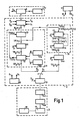
- Fig. 1 represents a first embodiment of a control device according to the invention applied in a weapon control system which is provided with a target sensor 1, the control device 2 and a weapon system 3.
- This figure shows a platform sensor unit 4 which is provided with suitable sensors for measuring the orientation S p and position P p of the platform on which the weapon control system is fitted.
- Target sensor 1 is fitted with a pulse radar apparatus 5 supplying bearing and range information of a target with respect to a line of sight of an antenna of the pulse radar apparatus.
- Target sensor 1 can also be an electro-optic sensor such as an IR or a TV camera, possibly provided with a laser range finder.
- the antenna is provided with aiming means 6, placing the antenna in the desired orientation by means of orientation readers recording the orientation S s of the antenna with respect to the platform.
- aiming means 6 are provided with servos and so-called synchros.
- the bearing and range information of the target, the information relating to the orientation S s of the antenna, the information with respect to the orientation S p of the platform and the data relating to the position P p of the platform are supplied to control device 2.
- the measured target data are, by means of data relating to the orientation S s of the antenna, the orientation S p and position P p of the platform, preferably converted (block 7) to a first reference coordinate system, which is preferably earth-orientated. Moreover, the measured target data are filtered ("target track filtering", block 7) for the purpose of control signals for aiming means 6.
- the converted target data P d (t1) indicated at regular intervals at a first point in time with t1 (block 8), are used to calculate a gun aiming point SP R (t1) for weapon system 3 (block 9).
- a future target position after this time of flight is calculated (block 10).
- This future hitting point TP(t1) calculated at a first point in time t1 is converted by means of data concerning the position P p of the platform to a relative future hitting point TP R (t1) with respect for the platform (block 11).
- a model of the projectile trajectory is used to make a new calculation (block 12) of the projectile time of flight TS(t1), which calculation is used as an improved estimation of the projectile time of flight in the new calculation of the future hitting point TP(t1).
- a relative gun aiming point SP R (t1) for weapon system 3 is calculated (block 12) by means of the projectile trajectory model.
- the projectile trajectory model uses stored ballistic and meteorological data B and M (blocks 12a and 12b).
- control signal S 1 When using the control device in a normal weapon control mode, indicated by control signal S 1, the calculated relative gun aiming point SP R (t1) is converted to platform coordinates by means of data concerning the orientation S p of the platform (block 13). On the basis of the converted gun aiming point, control signals are generated (block 13) for aiming means 14a which aim a launching system 14b.
- control device S1 Use of the control device in a mode suitable for assessment of the aiming of the weapon system at the target according to the invention is indicated with control signal S1.
- weapon system 3 is not controlled on the basis of gun aiming point SP R (t1), but on the basis of a previously calculated and stored (block 19) hitting point TP R (t2), which is valid at the present time t1.
- Time t2 relates to the point in time at which this hitting point was calculated.
- the calculated future hitting points TP(t1), a time validity TTP(t1) corresponding with this hitting point and the point in time t1 at which these data were calculated are stored in a memory (block 15) during a certain period of time.
- the time validity TTP(t1) is obtained by adding to t1 the corresponding projectile time of flight TS(t1).
- This memory consists of a cyclic buffer whose cycle time is longer than the longest expected projectile time of flight.
- two hitting points TP(t′) and TP(t ⁇ ) are taken from the memory in which the future hitting points are stored, together with the corresponding time validity TTP(t′) and TTP(t ⁇ ) for which t′ ⁇ t1 ⁇ t ⁇ (blocks 15 and 16).
- the present hitting point TP(t2), together with the time validity of t1 is calculated by means of a linear interpolation between hitting points TP(t′) and TP(t ⁇ ) (block 16).
- an embodiment may also store, during a particular time, the target trajectory data P d (t1) or data derived thereof. The present hitting point calculation will then have to be carried out at a time t1, on the basis of the stored target trajectory data which were valid at an earlier time t2.
- the present hitting points TP(t2) are converted by means of data P p , relating to the position of the platform (block 16a), to present hitting points TF R (t2) relative to the position of the platform. These relative present hitting points TP R (t2) are subsequently converted (block 13) by means of data S p , relating to the orientation of the platform, to a coordinate system connected to the platform for the purpose of generating control signals for continuous aiming of weapon system 3 at these present hitting points.
- a launching system 14b in the form of a gun has, for the purpose of the use of the control device in mode S1, been provided with a well-known barrel camera 17 for aligning the gun.
- a difference between the present hitting point and the present target position as visible on video 18 from barrel camera 17 may subsequently be further processed in various ways.
- the video information is continuously supplied to a user for assessment, which user is able to obtain an impression of the operation of the weapon control system.
- Another embodiment is obtained when assessment is automated by the calculation of quality values, such as hitting probability, by means of data concerning dispersion relating to the trajectory, effectiveness of the projectile and target dimensions.
- An embodiment including a barrel camera 17 is, strictly speaking, not required if the orientation of the gun has been calculated accurately enough. This orientation can be measured by the said readers, such as synchros, and compared by the control device with the stale hitting points.
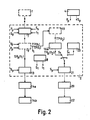
- Fig. 2 shows an embodiment of a control device in an application in a similar weapon control system which, for the purpose of aiming at the present hitting points, has been fitted with a second target sensor 22 provided with its own aiming means 20.
- the control device 2 is executed in such a way that, besides conversion of gun aiming points (block 13), simultaneous conversion of present hitting points is executed (block 21).
- the second target sensor is coupled in mode S1 to the control device and continuously aimed at the present hitting points. In mode S 1, the second target sensor is available for another weapon control channel 23.
- platform sensors 4 consist of means for once-only determination of the platform data relating to orientation S p and position P p .
- a distinction between earth-oriented coordinates and coordinates determined by the platform is not required. Conversion from and to relative coordinates is therefore no longer necessary.
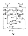
- Fig. 3 shows an embodiment of a control device applied in a weapon control system suitable for mounting on a moving platform.
- Platform sensors 4 continuously supply data relating to orientation S p , data relating to position P p , but also data relating to the own velocity V p of the platform.
- the platform sensors 4 may consist of well-known gyro's, acceleration and velocity meters.
- the control device by means of data relating to position P p and velocity V p of the platform, calculates the displacement of the platform at certain intervals at points in time indicated with t1 (block 24).
- Position P p (t1) at this time, velocity V p (t1) at this time and the time t1 are stored in a memory (block 25) during a certain period of time.
- This memory is executed as cyclic memory of which the cycle time exceeds the maximum expected projectile time of flight. Subsequently, the present hitting point TP(t2) (block 19) corresponding with a time t1 is corrected (block 16a) for own displacement ⁇ P p (t2) of the platform from time t2 till time t1. To determine this own displacement, two stored platform positions P p (t′) and P p (t ⁇ ) are retrieved from memory 25, with t′ ⁇ t2 ⁇ t ⁇ (block 26). Subsequently, the platform displacement ⁇ P p (t2) as from time t2 is found by linear interpolation between these platform positions (block 26).
Landscapes
- Engineering & Computer Science (AREA)
- General Engineering & Computer Science (AREA)
- Chemical & Material Sciences (AREA)
- Combustion & Propulsion (AREA)
- Aiming, Guidance, Guns With A Light Source, Armor, Camouflage, And Targets (AREA)
Applications Claiming Priority (2)
| Application Number | Priority Date | Filing Date | Title |
|---|---|---|---|
| NL8801576A NL8801576A (nl) | 1988-06-21 | 1988-06-21 | Inrichting en werkwijze voor sturing van een wapensysteem. |
| NL8801576 | 1988-06-21 |
Publications (2)
| Publication Number | Publication Date |
|---|---|
| EP0347968A1 true EP0347968A1 (de) | 1989-12-27 |
| EP0347968B1 EP0347968B1 (de) | 1996-10-30 |
Family
ID=19852494
Family Applications (1)
| Application Number | Title | Priority Date | Filing Date |
|---|---|---|---|
| EP89201478A Expired - Lifetime EP0347968B1 (de) | 1988-06-21 | 1989-06-08 | Verfahren und Vorrichtung zur Steuerung eines Waffensystems |
Country Status (6)
| Country | Link |
|---|---|
| EP (1) | EP0347968B1 (de) |
| JP (1) | JPH0244197A (de) |
| DE (1) | DE68927395T2 (de) |
| ES (1) | ES2094727T3 (de) |
| NL (1) | NL8801576A (de) |
| NO (1) | NO892538L (de) |
Cited By (1)
| Publication number | Priority date | Publication date | Assignee | Title |
|---|---|---|---|---|
| WO1996025675A1 (en) * | 1995-02-16 | 1996-08-22 | Hollandse Signaalapparaten B.V. | Fire control system |
Citations (8)
| Publication number | Priority date | Publication date | Assignee | Title |
|---|---|---|---|---|
| US3848509A (en) * | 1972-10-31 | 1974-11-19 | Us Navy | Closed-loop gun control system |
| FR2378318A1 (fr) * | 1977-01-21 | 1978-08-18 | Thomson Csf | Systeme de poursuite d'une cible mobile |
| WO1981000149A1 (en) * | 1979-06-29 | 1981-01-22 | Hollandse Signaalapparaten Bv | Automatic correction of aiming in firing at moving targets |
| US4320287A (en) * | 1980-01-25 | 1982-03-16 | Lockheed Electronics Co., Inc. | Target vehicle tracking apparatus |
| GB2095799A (en) * | 1981-03-27 | 1982-10-06 | Baasch Hans | An aiming device for use in firing at moving targets |
| EP0070541A2 (de) * | 1981-07-21 | 1983-01-26 | Siemens Aktiengesellschaft | Feuerleiteinrichtung für ein Flugabwehrsystem |
| EP0207521A1 (de) * | 1985-07-04 | 1987-01-07 | Contraves Ag | Zielvermessungssystem |
| US4647759A (en) * | 1983-07-07 | 1987-03-03 | The United States Of America As Represented By The Secretary Of The Air Force | Fire control apparatus for a laser weapon |
-
1988
- 1988-06-21 NL NL8801576A patent/NL8801576A/nl not_active Application Discontinuation
-
1989
- 1989-06-08 DE DE68927395T patent/DE68927395T2/de not_active Expired - Fee Related
- 1989-06-08 ES ES89201478T patent/ES2094727T3/es not_active Expired - Lifetime
- 1989-06-08 EP EP89201478A patent/EP0347968B1/de not_active Expired - Lifetime
- 1989-06-19 NO NO89892538A patent/NO892538L/no unknown
- 1989-06-19 JP JP1154793A patent/JPH0244197A/ja active Pending
Patent Citations (8)
| Publication number | Priority date | Publication date | Assignee | Title |
|---|---|---|---|---|
| US3848509A (en) * | 1972-10-31 | 1974-11-19 | Us Navy | Closed-loop gun control system |
| FR2378318A1 (fr) * | 1977-01-21 | 1978-08-18 | Thomson Csf | Systeme de poursuite d'une cible mobile |
| WO1981000149A1 (en) * | 1979-06-29 | 1981-01-22 | Hollandse Signaalapparaten Bv | Automatic correction of aiming in firing at moving targets |
| US4320287A (en) * | 1980-01-25 | 1982-03-16 | Lockheed Electronics Co., Inc. | Target vehicle tracking apparatus |
| GB2095799A (en) * | 1981-03-27 | 1982-10-06 | Baasch Hans | An aiming device for use in firing at moving targets |
| EP0070541A2 (de) * | 1981-07-21 | 1983-01-26 | Siemens Aktiengesellschaft | Feuerleiteinrichtung für ein Flugabwehrsystem |
| US4647759A (en) * | 1983-07-07 | 1987-03-03 | The United States Of America As Represented By The Secretary Of The Air Force | Fire control apparatus for a laser weapon |
| EP0207521A1 (de) * | 1985-07-04 | 1987-01-07 | Contraves Ag | Zielvermessungssystem |
Cited By (4)
| Publication number | Priority date | Publication date | Assignee | Title |
|---|---|---|---|---|
| WO1996025675A1 (en) * | 1995-02-16 | 1996-08-22 | Hollandse Signaalapparaten B.V. | Fire control system |
| NL9500285A (nl) * | 1995-02-16 | 1996-10-01 | Hollandse Signaalapparaten Bv | Vuurleidingssysteem. |
| AU689704B2 (en) * | 1995-02-16 | 1998-04-02 | Thales Nederland B.V. | Fire control system |
| US5920027A (en) * | 1995-02-16 | 1999-07-06 | Hollandse Signaalapparaten B.V. | Fire control system |
Also Published As
| Publication number | Publication date |
|---|---|
| EP0347968B1 (de) | 1996-10-30 |
| JPH0244197A (ja) | 1990-02-14 |
| NO892538L (no) | 1989-12-22 |
| NO892538D0 (no) | 1989-06-19 |
| DE68927395T2 (de) | 1997-05-15 |
| NL8801576A (nl) | 1990-01-16 |
| DE68927395D1 (de) | 1996-12-05 |
| ES2094727T3 (es) | 1997-02-01 |
Similar Documents
| Publication | Publication Date | Title |
|---|---|---|
| US5026158A (en) | Apparatus and method for displaying and storing impact points of firearm projectiles on a sight field of view | |
| US3955292A (en) | Apparatus for antiaircraft gunnery practice with laser emissions | |
| US4402250A (en) | Automatic correction of aiming in firing at moving targets | |
| EP0929787B1 (de) | Zielanvisierungssystem | |
| WO2001073369A1 (en) | Precision gunnery simulator system and method | |
| SE506468C2 (sv) | Träfflägesmarkerare för hagelgevärsskytte | |
| KR100928754B1 (ko) | 무기시스템의 조준 에러를 판단하기 위한 방법 및 장치와,이 장치의 용도 | |
| US8303308B2 (en) | Method and system for fire simulation | |
| US4253249A (en) | Weapon training systems | |
| US8944821B2 (en) | Simulation system and method for determining the compass bearing of directing means of a virtual projectile/missile firing device | |
| GB2107835A (en) | Correcting, from one shot to the next, the firing of a weapon | |
| RU2007124062A (ru) | Способ стрельбы боевой машины по цели (варианты) и информационно-управляющая система для его осуществления | |
| KR100917932B1 (ko) | 무기시스템의 조준 에러를 판단하기 위한 방법 및 장치와,이 장치의 용도 | |
| CA2023659A1 (en) | Method and apparatus for improving the accuracy of fire | |
| KR100914320B1 (ko) | 곡사화기 모의 훈련 장치 및 방법 | |
| GB2506733A (en) | Method for determining the probability of hitting a target with a shot, and for displaying the determined probability in an aiming device | |
| US3965582A (en) | Gunnery practice method and apparatus | |
| EP0347968A1 (de) | Verfahren und Vorrichtung zur Steuerung eines Waffensystems | |
| KR890000098B1 (ko) | 항공기의 광학관측시야자동교정시스템 | |
| CN112818546A (zh) | 一种直瞄弹药对移动目标命中概率的计算方法 | |
| EP1643206A1 (de) | Simulationssystem, -verfahren und Computerprogramm | |
| CA2366526C (en) | Shooting simulation method | |
| EP1580516A1 (de) | Vorrichtung und Verfahren zum Auswerten des Zielverhaltens einer Waffe | |
| EP4374128B1 (de) | System zur auswahl eines chokes | |
| JP2000249496A (ja) | 照準装置 |
Legal Events
| Date | Code | Title | Description |
|---|---|---|---|
| PUAI | Public reference made under article 153(3) epc to a published international application that has entered the european phase |
Free format text: ORIGINAL CODE: 0009012 |
|
| AK | Designated contracting states |
Kind code of ref document: A1 Designated state(s): BE CH DE ES FR GB IT LI NL SE |
|
| 17P | Request for examination filed |
Effective date: 19900609 |
|
| RAP1 | Party data changed (applicant data changed or rights of an application transferred) |
Owner name: HOLLANDSE SIGNAALAPPARATEN B.V. |
|
| 17Q | First examination report despatched |
Effective date: 19920828 |
|
| GRAG | Despatch of communication of intention to grant |
Free format text: ORIGINAL CODE: EPIDOS AGRA |
|
| GRAH | Despatch of communication of intention to grant a patent |
Free format text: ORIGINAL CODE: EPIDOS IGRA |
|
| GRAH | Despatch of communication of intention to grant a patent |
Free format text: ORIGINAL CODE: EPIDOS IGRA |
|
| GRAA | (expected) grant |
Free format text: ORIGINAL CODE: 0009210 |
|
| AK | Designated contracting states |
Kind code of ref document: B1 Designated state(s): BE CH DE ES FR GB IT LI NL SE |
|
| ITF | It: translation for a ep patent filed | ||
| REF | Corresponds to: |
Ref document number: 68927395 Country of ref document: DE Date of ref document: 19961205 |
|
| REG | Reference to a national code |
Ref country code: CH Ref legal event code: NV Representative=s name: ISLER & PEDRAZZINI AG |
|
| REG | Reference to a national code |
Ref country code: ES Ref legal event code: FG2A Ref document number: 2094727 Country of ref document: ES Kind code of ref document: T3 |
|
| ET | Fr: translation filed | ||
| PLBE | No opposition filed within time limit |
Free format text: ORIGINAL CODE: 0009261 |
|
| STAA | Information on the status of an ep patent application or granted ep patent |
Free format text: STATUS: NO OPPOSITION FILED WITHIN TIME LIMIT |
|
| 26N | No opposition filed | ||
| PGFP | Annual fee paid to national office [announced via postgrant information from national office to epo] |
Ref country code: CH Payment date: 19990517 Year of fee payment: 11 |
|
| PGFP | Annual fee paid to national office [announced via postgrant information from national office to epo] |
Ref country code: SE Payment date: 19990518 Year of fee payment: 11 |
|
| PGFP | Annual fee paid to national office [announced via postgrant information from national office to epo] |
Ref country code: FR Payment date: 19990528 Year of fee payment: 11 |
|
| PGFP | Annual fee paid to national office [announced via postgrant information from national office to epo] |
Ref country code: ES Payment date: 19990601 Year of fee payment: 11 |
|
| PGFP | Annual fee paid to national office [announced via postgrant information from national office to epo] |
Ref country code: GB Payment date: 19990602 Year of fee payment: 11 |
|
| PGFP | Annual fee paid to national office [announced via postgrant information from national office to epo] |
Ref country code: NL Payment date: 19990615 Year of fee payment: 11 |
|
| PGFP | Annual fee paid to national office [announced via postgrant information from national office to epo] |
Ref country code: DE Payment date: 19990616 Year of fee payment: 11 |
|
| PGFP | Annual fee paid to national office [announced via postgrant information from national office to epo] |
Ref country code: BE Payment date: 19990623 Year of fee payment: 11 |
|
| PG25 | Lapsed in a contracting state [announced via postgrant information from national office to epo] |
Ref country code: GB Free format text: LAPSE BECAUSE OF NON-PAYMENT OF DUE FEES Effective date: 20000608 |
|
| PG25 | Lapsed in a contracting state [announced via postgrant information from national office to epo] |
Ref country code: SE Free format text: LAPSE BECAUSE OF NON-PAYMENT OF DUE FEES Effective date: 20000609 Ref country code: ES Free format text: THE PATENT HAS BEEN ANNULLED BY A DECISION OF A NATIONAL AUTHORITY Effective date: 20000609 |
|
| PG25 | Lapsed in a contracting state [announced via postgrant information from national office to epo] |
Ref country code: LI Free format text: LAPSE BECAUSE OF NON-PAYMENT OF DUE FEES Effective date: 20000630 Ref country code: CH Free format text: LAPSE BECAUSE OF NON-PAYMENT OF DUE FEES Effective date: 20000630 Ref country code: BE Free format text: LAPSE BECAUSE OF NON-PAYMENT OF DUE FEES Effective date: 20000630 |
|
| BERE | Be: lapsed |
Owner name: HOLLANDSE SIGNAALAPPARATEN B.V. Effective date: 20000630 |
|
| PG25 | Lapsed in a contracting state [announced via postgrant information from national office to epo] |
Ref country code: NL Free format text: LAPSE BECAUSE OF NON-PAYMENT OF DUE FEES Effective date: 20010101 |
|
| GBPC | Gb: european patent ceased through non-payment of renewal fee |
Effective date: 20000608 |
|
| REG | Reference to a national code |
Ref country code: CH Ref legal event code: PL |
|
| EUG | Se: european patent has lapsed |
Ref document number: 89201478.8 |
|
| PG25 | Lapsed in a contracting state [announced via postgrant information from national office to epo] |
Ref country code: FR Free format text: LAPSE BECAUSE OF NON-PAYMENT OF DUE FEES Effective date: 20010228 |
|
| NLV4 | Nl: lapsed or anulled due to non-payment of the annual fee |
Effective date: 20010101 |
|
| REG | Reference to a national code |
Ref country code: FR Ref legal event code: ST |
|
| PG25 | Lapsed in a contracting state [announced via postgrant information from national office to epo] |
Ref country code: DE Free format text: LAPSE BECAUSE OF NON-PAYMENT OF DUE FEES Effective date: 20010403 |
|
| REG | Reference to a national code |
Ref country code: ES Ref legal event code: FD2A Effective date: 20020204 |
|
| PG25 | Lapsed in a contracting state [announced via postgrant information from national office to epo] |
Ref country code: IT Free format text: LAPSE BECAUSE OF NON-PAYMENT OF DUE FEES;WARNING: LAPSES OF ITALIAN PATENTS WITH EFFECTIVE DATE BEFORE 2007 MAY HAVE OCCURRED AT ANY TIME BEFORE 2007. THE CORRECT EFFECTIVE DATE MAY BE DIFFERENT FROM THE ONE RECORDED. Effective date: 20050608 |