EP0070541A2 - Feuerleiteinrichtung für ein Flugabwehrsystem - Google Patents
Feuerleiteinrichtung für ein Flugabwehrsystem Download PDFInfo
- Publication number
- EP0070541A2 EP0070541A2 EP82106430A EP82106430A EP0070541A2 EP 0070541 A2 EP0070541 A2 EP 0070541A2 EP 82106430 A EP82106430 A EP 82106430A EP 82106430 A EP82106430 A EP 82106430A EP 0070541 A2 EP0070541 A2 EP 0070541A2
- Authority
- EP
- European Patent Office
- Prior art keywords
- prediction
- time
- destination
- control device
- fire control
- Prior art date
- Legal status (The legal status is an assumption and is not a legal conclusion. Google has not performed a legal analysis and makes no representation as to the accuracy of the status listed.)
- Granted
Links
Images
Classifications
-
- F—MECHANICAL ENGINEERING; LIGHTING; HEATING; WEAPONS; BLASTING
- F41—WEAPONS
- F41G—WEAPON SIGHTS; AIMING
- F41G5/00—Elevating or traversing control systems for guns
- F41G5/08—Ground-based tracking-systems for aerial targets
Definitions
- the invention relates to a fire control device for an air defense system, in which a destination prediction and the weapon reserve are calculated in a computer using the flight destination data obtained by sensors (e.g. radar device).
- sensors e.g. radar device
- the defense against flight targets using a fire control device is based on the ongoing tracking of the flight targets with the help of suitable sensors e.g. instructed with radars.
- the data obtained from the sensors not only provide the current destination, but are also required to predict the destination for a future point in time.
- the destination prediction in turn is a prerequisite for determining the weapon reserve, which is calculated in a reserve calculator.
- the destination prediction is in principle error-prone, so that a predicted destination and the destination actually present after the prediction time have expired do not match. The reduction of the prediction error is crucial for a quick successful defense against flight targets.
- the invention has for its object to further improve the accuracy of the destination prediction with reasonable effort.
- This object is achieved according to the invention in that the calculated prediction of the destination is continuously compared with the actual destination determined by measurement when the prediction time has elapsed, and in that the deviation (error) determined by the comparison is used to correct the respectively calculated current prediction of the destination becomes.
- the correction of the target location of a prediction can be formed by averaging several calculated errors. It can also be advantageous to use the tendency of an error change, which can be identified by comparing successive errors, to correct the prediction of the destination.
- the prediction period is selected so that the probability of a flight maneuver within the prediction period is low.
- a correction value can be calculated as follows.
- Tv (t) means the prediction time.
- the measured value of the destination obtained at time (t + Tv (t)) is:
- the prediction is optionally corrected with the error:
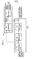
- the reserve computer VHR consists of a stage KT for coordinate transformation and smoothing of the data for the destination, a stage BZ for calculating the target speed and acceleration and a stage VO for predicting a location value for the time (t + Tv).
- the polar radar data are supplied to the reserve computer at time T.
- the transformation and smoothing stage KT supplies smoothed Cartesian location data at its output, which are calculated back to the time t, both to the next stage BZ for calculating the target speed and acceleration and to the circuit part VK for correcting the lead.
- the output of stage BZ supplies the smoothed location and speed data for the subsequent stage VO?
- the lead correction part VK consists of the circuit part SP for storing the prediction values and a comparison circuit for Comparison of the prediction values with the actual destination after the prediction time.
- the location predictions with the errors made in the past are corrected in an addition process.
- the meeting point for the meeting time (t + Tv) determined by the lead calculator VHR at time t is compared with the measured destination at the time (t + Tv) and the result of the lead calculation is improved by adding the correction value.
- the lead angles of the weapons to be controlled with the fire control device are corrected with the output data of the lead correction part.
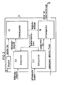
- the function of the memory and the comparison circuit SP of the lead correction part VK is further broken down in the block diagram according to FIG. 2.
- the correction level FK of the lead correction part VK requires no further explanations, since it consists of a known addition circuit.
- the meeting point determined by the reserve computer at time t is stored in a location memory OSP and the associated meeting time in a time memory ZSP.
- the meeting time results from the sum of the time t and the floor flight time.
- the memories ZSP and OSP are known memory circuits which have memory locations for 1 to n prediction times or predicted location values.
- a known timer ZG is started, which carries out a time measurement with respect to the start time t.
- a time comparator ZK On the input side, the time comparator ZK is connected to the timer ZG, which supplies the current time, and to the output of the time memory ZSP, which supplies the first prediction time. On the output side, the time comparator ZK sends a signal to the location comparator OK, which includes a comparison permission for the data of the first stored location and the data of the measured current destination.
- the determined in Ortskomparator OK error of the destination prediction is supplied to the K q rrekturculture FK and added to the result of the Vor mental illness.
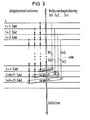
- a reserve calculation is carried out for each of the target data arriving one after the other and the meeting point (location) and the associated meeting point are stored one after the other in the local memory 0SP or time memory ZSP of the lead correction circuit VK. According to FIG. 3, these processes are repeated in the order given until the timer status becomes greater than or equal to the first meeting time. After fulfilling this condition, the following steps follow.
- the time comparator ZK determines whether the current time -t + n. Clock of the timer and the first prediction time Tv1 are the same. If this case has occurred, the time comparator ZK gives permission to compare the measured current location with the predicted first stored meeting point location in the location comparator OK.
- the target position of the weapon to be controlled is corrected with the difference between the prediction value (first meeting point) and the measured value. Then the first meeting point in the local memory OSP and the first meeting time in the time memory ZSP by a time comparator ZK The supplied memory reset command is deleted so that the second meeting point (location) and the second meeting point become the first and the third meeting point (location) and the third meeting point second and so on.
- the counting clock for the timer mechanism in a synchronously clocked system is the same as the clock with which the radar data is supplied, while the clock in an asynchronous free-running system is selected according to the desired time resolution.
- the (n + 1) th meeting point and meeting point becomes the first meeting point and meeting point.
- Fig. 3 is a complete There is no equality in time between measuring points and meeting points. This is corrected by interpolating the meeting point data to the time of the measuring point data.
Abstract
Description
- Die Erfindung bezieht sich auf eine Feuerleiteinrichtung für ein Flugabwehrsystem, bei der mit den durch Sensoren (z.B. Radargerät) erhaltenen Flugzieldaten in einem Rechner eine Zielortvorhersage und der Waffenvorhalt berechnet wird.
- Die Abwehr von Flugzielen unter Verwendung einer Feuerleiteinrichtung ist auf die laufende Verfolgung der Flugziele mit Hilfe geeigneter Sensoren z.B. mit Radargeräten angewiesen. Die von. den Sensoren-erhaltenen Daten liefern nicht nur den aktuellen Zielort, sondern sind auch zur Vorhersage des Zielortes für einen zukünftigen Zeitpunkt erforderlich. Die Zielortvorhersage wiederum ist Voraussetzung für die Bestimmung des Waffenvorhaltes, der in einem Vorhalterechner berechnet wird. Die Zielortvorhersage ist prinzipiell fehlerbehaftet, so daß ein vorhergesagter Zielort und der nach Ablauf der Vorhersagezeit tatsächlich vorliegende Zielort nicht übereinstimmen. Für eine schnelle erfolgreiche Abwehr von Flugzielen ist die Verringerung des Vorhersagefehlers ausschlaggebend.
- Verfahren, die unter Verwendung einer bestimmten Anzahl zurückliegender Sensor-Meßdaten versuchen, durch geeignete Mittelwertbildung oder durch Filterverfahren, z.B. Kalman-Filterung, den wahrscheinlichsten Zustandsvektor des Zieles (Ort Geschwindigkeit, Beschleunigung) über der Zeit t zu ermitteln, liefern nicht die gewünschte Genauigkeit, wenn das Ziel Flugmanöver ausführt, die nur mit einer gewissen Zeitkonstante nachvollzogen werden können. Selbst bei mathematisch optimalen und sehr rechenintensiven Verfahren mit automatischer Zeitkonstantenanpassung an das Zielverhalten ist das Ergebnis bei Flugmanöve.rn in der Praxis meistens unbefriedigend, da die-Zeitkonstantenanpassung zu langsam erfolgt.
- Der Erfindung liegt die Aufgabe zugrunde, die Genauigkeit der Zielortvorhersage mit vertretbarem Aufwand weiter zu verbessern. Diese Aufgabe wird gemäß der Erfindung dadurch gelöst, daß die berechnete Vorhersage des Zielortes laufend mit dem bei Ablauf der Vorhersagezeit durch Messung ermittelten tatsächlichen Zielort verglichen wird und daß die durch den Vergleich ermittelte Abweichung (Fehler) zur Korrektur der jeweils berechneten aktuellen Vorhersage des Zielortes verwendet wird.
- Ist der Fehler größer als eine empirisch ermittelte, von der Güte des Radargerätes abhängige maximale Fehleramplitude für geradlinige unbeschleunigte Zielbewegungen, so wird auf ein Flugmanöver des Zieles geschlossen. Bei der Abgabe der aktuellen Zielortvorhersage ist dann dem unkorrigierten Vorhersagewert der erkannte Fehler hinzuzuaddieren. Gemäß einer vorteilhaften Weiterbildung der Erfindung kann die Korrektur des Zielortes einer Vorhersage durch Mittelwertbildung aus mehreren errechneten Fehlern gebildet sein. Ebenso kann es vorteilhaft sein, die durch Vergleich aufeinander folgender Fehler erkennbare Tendenz einer Fehleränderung zur Korrektur der Vorhersage des Zielortes heranzuziehen.
- Gemäß einer vorteilhaften Ausgestaltung der Erfindung wird die Vorhersagedauer so gewählt, daß die Wahrscheinlichkeit eines Flugmanövers innerhalb der Vorhersagedauer gering ist.
- Für die durch Vergleich ermittelte Abweichung läßt sich ein Korrekturwert wie folgt errechnen.
- Für die zum Zeitpunkt t abgegebene Zielortvorhersage für den Zeitpunkt (t + Tv (t)) gilt:

- Darin bedeutet Tv (t) die Vorhersagedauer.
- Der zum Zeitpunkt (t + Tv (t)) erhaltene Meßwert des Zielortes beträgt:

- Der zum Zeitpunkt (t + Tv (t)) durch Vergleich erkannte Fehler zwischen Vorhersage und Messung beträgt:

- Nach der Entscheidung, ob der Fehler größer ist als eine maximal zulässige Fehleramplitude bei geradlinigen unbeschleunigten Zielbewegungen, erfolgt gegebenenfalls eine additive Korrektur der Vorhersage mit dem Fehler:

- Die Erfindung und weitere Einzelheiten der Erfindung werden anhand der Figuren näher erläutert.
- ,Es zeigen
- Fig. 1 ein Blockschaltbild einer Einrichtung für ein Flugabwehrsystem gemäß der Erfindung,
- Fig. 2 ein Blockschaltbild-mit einer detaillierten Aufgliederung des Vorhaltekorrkturteils aus Fig. 1,
- Fig. 3 eine Darstellung eines Zeitdiagramms der Funktionen der Anordnung nach Fig. 1 und.2.
- Das Blockschaltbild nach Fig. 1 zeigt den prinzipiellen Aufbau eines bekannten Vorhalterechners VHR mit dem Schaltungsteil VK zur Korrektur des Vorhaltes gemäß der Erfindung. Der Vorhalterechner VHR besteht aus einer Stufe KT zur Koordinatentransformation und Glättung der Daten für den Zielort, einer Stufe BZ zur Berechnung der Zielgeschwindigkeit und Beschleunigung und einer Stufe VO zur Vorhersage eines Ortswertes für den Zeitpunkt (t + Tv). Dem Vorhalterech-, ner werden die polaren Radardaten zum Zeitpunkt T zugeführt. Die Transformations- und Glättungsstufe KT liefert an ihrem Ausgang geglättete kartesische Ortsdaten, die auf den Zeitpunkt t zurückgerechnet sind, sowohl an die nächste Stufe BZ zur Berechnung der Zielgeschwindigkeit und Beschleunigung als auch an den Schaltungsteil VK zur Korrektur des Vorhaltes. Der Ausgang der Stufe BZ liefert die ebenfalls auf den Zeitpunkt t zurückgerechneten geglätteten Orts-und Geschwindigkeitsdaten für die nachfolgende Stufe VO? in der die Vorhersage eines Ortswertes für den Zeitpunkt (t + Tv) berechnet wird. Das Ergebnis der Vorhalterechnung der Stufe VO wird einem zweiten Eingang des Schaltungsteils VK zur Korrektur des Vorhaltes zugeführt. Der Vorhaltekorrekturteil VK besteht aus dem Schaltungsteil SP zur Speicherung der Vorhersagewerte und aus einer Vergleichsschaltung zum Vergleich der Vorhersagewerte mit dem tatsächlichen Zielort nach der Vorhersagezeit. In einer weiteren Stufe FK des Vorhaltekorrekturteils VK erfolgt in einem Additionsvorgang die Korrektur der Ortsvorhersagen mit den in der Vergangenheit gemachten Fehlern. Im Vorhaltekorrekturteil VK wird somit der vom Vorhalterechner VHR zum Zeitpunkt t ermittelte Treffpunkt für die Treffzeit (t + Tv) mit dem vermessenen Zielort zur Zeit (t + Tv) verglichen und durch Addition des Korrekturwertes das Ergebnis der Vorhalterechnung verbessert. Die Vorhaltewinkel der mit der Feuerleiteinrichtung zu steuernden Waffen werden mit den Ausgangsdaten des Vorhaltekorrekturteils korrigiert.
- Im Blockschaltbild nach Fig. 2 ist die Funktion des Speichers und der Vergleichsschaltung SP des Vorhaltekorrekturteils VK weiter aufgeschlüsselt. Die Korrekturstufe FK des Vorhaltekorrekturteils VK bedarf keiner weiteren Ausführungen, da sie aus einer bekannten Additionsschaltung besteht.
- Der zum Zeitpunkt t vom Vorhalterechner ermittelte Treffpunkt wird in einem Ortsspeicher OSP und der zugehörige Treffzeitpunkt in einem Zeitspeicher ZSP abgespeichert. Der Treffzeitpunkt ergibt sich bei-der Vorhalterechnung aus der Summe der Zeit t und der Geschoßflugzeit, Bei den Speichern ZSP und OSP handelt es sich um bekannte Speicherschaltungen, die Speicherplätze für 1 bis n Vorhersagezeitpunkte bzw. vorhergesagte Ortswerte aufweisen. Mit Beginn der Einspeicherung wird ein bekannter Zeitgeber ZG gestartet, der eine Zeitmessung bezüglich der Startzeit t durchführt.
- Weitere Schaltungsteile der.Speicher- und Vergleichsschaltung SP sind ein Zeitkomparator ZK und ein Ortskomparator OK. Eingangsseitig ist der Zeitkomparator ZK mit dem Zeitgeber ZG,-der die aktuelle Zeit liefert und mit dem Ausgang des Zeitspeichers ZSP, der den ersten Vorhersagezeitpunkt liefert, verbunden. Vom Zeitkomparator ZK gelangt ausgangsseitig ein Signal an den Ortskomparator OK, das eine Vergleichserlaubnis für die Daten des ersten gespeicherten Ortes und die Daten des vermessenen aktuellen Zielortes beinhaltet. Der im Ortskomparator OK ermittelte Fehler der Zielortsvorhersage wird der Kqrrekturstufe FK zugeführt und zum Ergebnis der Vorhälterechnung hinzuaddiert.
- Von den nacheinander eintreffenden Zieldaten wird jeweils eine Vorhalteberechnung durchgeführt und nacheinander Treffpunkt (Ort) und der zugehörige Treffzeitpunkt im Ortsspeicher 0SP bzw. Zeitspeicher ZSP der Vorhaltekorrekturschaltung VK abgespeichert. Diese Vorgänge wiederholen sich gemäß Fig. 3 in der angegebenen Reihenfolge solange, bis der Zeitgeberstand größer oder gleich der ersten Treffzeit wird. Nach Erfüllung dieser Bedingung schließen sich die folgenden beschriebenen Schritte an. Im Zeitkomparator ZK wird festgestellt, ob die aktuelle Zeit -t + n . Takt des Zeitgebers und der erste Vorhersagezeitpunkt Tv1 gleich groß sind. Ist dieser Fall eingetreten, gibt der Zeitkomparator ZK eine Vergleichserlaubnis des vermessenen aktuellen Ortes mit dem vorhergesagten ersten gespeicherten Treffpunktort im Ortskomparator OK. Mit der Differenz zwischen dem Vorhersagewert (erster Treffpunkt) und dem Meßwert wird die Sollposition der zu steuernden Waffe korrigiert. Danach werden der erste Treffpunkt im Ortsspeicher OSP und die erste Treffzeit im Zeitspeicher ZSP durch einen vom Zeitkomparator ZK gelieferten Speicherrücksetzbefehl gelöscht, so daß der zweite Treffpunkt (Ort) und der zweite Treffzeitpunkt zum ersten und der dritte Treffpunkt (Ort) und der dritte Treffzeitpunkt zum zweiten wird usw..
- Der Zähltakt für den Zeitgebermechanismus ist in einem synchron getakteten System gleich dem Zeittakt, mit der die Radardaten geliefert werden, während der Takt in einem asynchron freilaufenden System nach der gewünschten Zeitauflösung gewählt wird.
- Bei einem synchron getakteten System können mehrere aufeinander folgend abgespeicherte Treffzeiten auf absolute Treffzeitpunkte führen, die zeitlich geringer auseinander liegen als die Taktzeit. Entsprechendes gilt in einem asynchron freilaufenden System für die größtmögliche Schrittweite des Zählers. Dieser Vorgang ist in Fig. 3 im zweiten Vergleich dargestellt.. In diesem Falle ist nicht nur der erste Treffpunkt und Treffzeitpunkt aus den Speichern zu eliminieren, sondern auch alle folgenden Treffpunkte und Treffzeitpunkte, die zeitlich zu nah am ersten Treffpunkt liegen. Andernfalls würde der Zählvorgang auf der linken Seite der Fig. 3 nicht mehr mit den Treffzeiten auf der rechten Seite dieses Zeitdiagramms übereinstimmen.
- Wird eine Anzahl von n Treffpunkten und Treffzeitpunkten gleichzeitig aus dem Speicher eliminiert, so wird der (n + 1)te Treffpunkt und Treffzeitpunkt zum ersten Treffpunkt und Treffzeitpunkt.
- Wie aus der Fig. 3 ersichtlich, ist eine völlige zeitliche Gleichheit zwischen Meßpunkten und Treff- punkten nicht gegeben. Diese wird durch Interpolation der Treffpunktdaten auf die Zeit der Meßpunktdaten korrigiert.
Claims (4)
Priority Applications (1)
| Application Number | Priority Date | Filing Date | Title |
|---|---|---|---|
| AT82106430T ATE49654T1 (de) | 1981-07-21 | 1982-07-16 | Feuerleiteinrichtung fuer ein flugabwehrsystem. |
Applications Claiming Priority (2)
| Application Number | Priority Date | Filing Date | Title |
|---|---|---|---|
| DE3128761A DE3128761C2 (de) | 1981-07-21 | 1981-07-21 | Feuerleiteinrichtung für ein Flugabwehrsystem |
| DE3128761 | 1981-07-21 |
Publications (3)
| Publication Number | Publication Date |
|---|---|
| EP0070541A2 true EP0070541A2 (de) | 1983-01-26 |
| EP0070541A3 EP0070541A3 (en) | 1985-10-09 |
| EP0070541B1 EP0070541B1 (de) | 1990-01-17 |
Family
ID=6137380
Family Applications (1)
| Application Number | Title | Priority Date | Filing Date |
|---|---|---|---|
| EP82106430A Expired - Lifetime EP0070541B1 (de) | 1981-07-21 | 1982-07-16 | Feuerleiteinrichtung für ein Flugabwehrsystem |
Country Status (3)
| Country | Link |
|---|---|
| EP (1) | EP0070541B1 (de) |
| AT (1) | ATE49654T1 (de) |
| DE (1) | DE3128761C2 (de) |
Cited By (1)
| Publication number | Priority date | Publication date | Assignee | Title |
|---|---|---|---|---|
| EP0347968A1 (de) * | 1988-06-21 | 1989-12-27 | Hollandse Signaalapparaten B.V. | Verfahren und Vorrichtung zur Steuerung eines Waffensystems |
Citations (1)
| Publication number | Priority date | Publication date | Assignee | Title |
|---|---|---|---|---|
| US3848509A (en) * | 1972-10-31 | 1974-11-19 | Us Navy | Closed-loop gun control system |
Family Cites Families (2)
| Publication number | Priority date | Publication date | Assignee | Title |
|---|---|---|---|---|
| US3798795A (en) * | 1972-07-03 | 1974-03-26 | Rmc Res Corp | Weapon aim evaluation system |
| US4146780A (en) * | 1976-12-17 | 1979-03-27 | Ares, Inc. | Antiaircraft weapons system fire control apparatus |
-
1981
- 1981-07-21 DE DE3128761A patent/DE3128761C2/de not_active Expired
-
1982
- 1982-07-16 AT AT82106430T patent/ATE49654T1/de not_active IP Right Cessation
- 1982-07-16 EP EP82106430A patent/EP0070541B1/de not_active Expired - Lifetime
Patent Citations (1)
| Publication number | Priority date | Publication date | Assignee | Title |
|---|---|---|---|---|
| US3848509A (en) * | 1972-10-31 | 1974-11-19 | Us Navy | Closed-loop gun control system |
Cited By (1)
| Publication number | Priority date | Publication date | Assignee | Title |
|---|---|---|---|---|
| EP0347968A1 (de) * | 1988-06-21 | 1989-12-27 | Hollandse Signaalapparaten B.V. | Verfahren und Vorrichtung zur Steuerung eines Waffensystems |
Also Published As
| Publication number | Publication date |
|---|---|
| ATE49654T1 (de) | 1990-02-15 |
| DE3128761A1 (de) | 1983-04-28 |
| EP0070541A3 (en) | 1985-10-09 |
| EP0070541B1 (de) | 1990-01-17 |
| DE3128761C2 (de) | 1986-01-02 |
Similar Documents
| Publication | Publication Date | Title |
|---|---|---|
| DE2636925C2 (de) | ||
| DE112017008157T5 (de) | Hinderniserkennungsvorrichtung und Hinderniserkennungsverfahren | |
| DE10236900A1 (de) | Verfahren und System zum Bitfehlerratentesten in minimaler Zeit | |
| DE3716606C2 (de) | ||
| EP1150186B1 (de) | Modellbasierte Online-Optimierung | |
| EP0291553A1 (de) | Verfahren zur Regelung einer Differential-Dosierwaage, insbesondere für Schüttgüter, und Differential-Dosierwaage zur Durchführung des Verfahrens | |
| CH660807A5 (de) | Digitaler ballistikrechner fuer ein feuerleitsystem einer rohrwaffe. | |
| DE2600023C2 (de) | Vorrichtung zur Bestimmung der Standardabweichung von Meßwerten eines Gegenstandsmerkmals von einem Zielwert | |
| WO2019149664A1 (de) | Verfahren zum ermitteln eines zeitlichen verlaufs einer messgrösse, prognosesystem, aktorsteuerungssystem, verfahren zum trainieren des aktorsteuerungssystems, trainingssystem, computerprogramm und maschinenlesbares speichermedium | |
| EP0070541B1 (de) | Feuerleiteinrichtung für ein Flugabwehrsystem | |
| DE3540066C2 (de) | Prozeß-Eingabe/Ausgabe-Gerät für eine Folgesteuervorrichtung | |
| EP3724610B1 (de) | Verfahren zum betreiben eines magnetisch-induktiven durchflussmessgeräts und magnetisch-induktives durchflussmessgerät | |
| DE2318856A1 (de) | Zielobjektauswerter fuer marine-ueberwasserradaranlage | |
| DE3624608A1 (de) | Verfahren und anordnung zur automatischen steuerung von luftbildaufnahmekameras | |
| DE4035520C2 (de) | Verfahren und Anordnung zur Messung der Geschwindigkeit eines Fahrzeuges | |
| DE102020212127A1 (de) | Verfahren zur Überprüfung einer technischen Funktion einer elektrischen und/oder mechanischen ersten Vorrichtung eines Eisenbahnsystems | |
| DE2907543C1 (de) | Feuerleiteinrichtung fuer ein Flugabwehrsystem | |
| EP3295126B1 (de) | Verfahren zum bestimmen von zuständen eines systems mittels eines schätzfilters | |
| DE3222255C2 (de) | ||
| EP0992758A1 (de) | Verfahren und Vorrichtung zur Berechnung und Korrektur der Zerlegungszeit eines drallstabilisierten programmierbaren Geschosses | |
| DE3047016C2 (de) | ||
| EP1186908A2 (de) | Verfahren zum Verfolgen eines sich bewegenden Ziels | |
| DE1165459B (de) | Einrichtung zur Vorausbestimmung des oder der Winkel, unter dem oder denen zu einem bestimmten Zeitpunkt ein Flugkoerper seinen Startort verlassen muss, um mit einem vorausbestimmten Ziel zu kollidieren | |
| DE1937093C (de) | Recheneinrichtung zur Erzeugung eines für den Verschleiß eines Geschützrohres charakteristischen Signals | |
| DE2809273C2 (de) | Taxameter |
Legal Events
| Date | Code | Title | Description |
|---|---|---|---|
| PUAI | Public reference made under article 153(3) epc to a published international application that has entered the european phase |
Free format text: ORIGINAL CODE: 0009012 |
|
| AK | Designated contracting states |
Designated state(s): AT BE CH FR GB IT LI NL |
|
| 17P | Request for examination filed |
Effective date: 19841219 |
|
| PUAL | Search report despatched |
Free format text: ORIGINAL CODE: 0009013 |
|
| AK | Designated contracting states |
Designated state(s): AT BE CH FR GB IT LI NL |
|
| 17Q | First examination report despatched |
Effective date: 19871127 |
|
| GRAA | (expected) grant |
Free format text: ORIGINAL CODE: 0009210 |
|
| AK | Designated contracting states |
Kind code of ref document: B1 Designated state(s): AT BE CH FR GB IT LI NL |
|
| REF | Corresponds to: |
Ref document number: 49654 Country of ref document: AT Date of ref document: 19900215 Kind code of ref document: T |
|
| ET | Fr: translation filed | ||
| ITF | It: translation for a ep patent filed |
Owner name: STUDIO JAUMANN |
|
| GBT | Gb: translation of ep patent filed (gb section 77(6)(a)/1977) | ||
| PGFP | Annual fee paid to national office [announced via postgrant information from national office to epo] |
Ref country code: GB Payment date: 19900614 Year of fee payment: 9 |
|
| PGFP | Annual fee paid to national office [announced via postgrant information from national office to epo] |
Ref country code: AT Payment date: 19900704 Year of fee payment: 9 |
|
| PGFP | Annual fee paid to national office [announced via postgrant information from national office to epo] |
Ref country code: BE Payment date: 19900719 Year of fee payment: 9 |
|
| PGFP | Annual fee paid to national office [announced via postgrant information from national office to epo] |
Ref country code: FR Payment date: 19900724 Year of fee payment: 9 |
|
| ITTA | It: last paid annual fee | ||
| PGFP | Annual fee paid to national office [announced via postgrant information from national office to epo] |
Ref country code: NL Payment date: 19900731 Year of fee payment: 9 |
|
| PGFP | Annual fee paid to national office [announced via postgrant information from national office to epo] |
Ref country code: CH Payment date: 19901024 Year of fee payment: 9 |
|
| PLBE | No opposition filed within time limit |
Free format text: ORIGINAL CODE: 0009261 |
|
| STAA | Information on the status of an ep patent application or granted ep patent |
Free format text: STATUS: NO OPPOSITION FILED WITHIN TIME LIMIT |
|
| 26N | No opposition filed | ||
| PG25 | Lapsed in a contracting state [announced via postgrant information from national office to epo] |
Ref country code: GB Effective date: 19910716 Ref country code: AT Effective date: 19910716 |
|
| PG25 | Lapsed in a contracting state [announced via postgrant information from national office to epo] |
Ref country code: LI Effective date: 19910731 Ref country code: CH Effective date: 19910731 Ref country code: BE Effective date: 19910731 |
|
| BERE | Be: lapsed |
Owner name: SIEMENS A.G. Effective date: 19910731 |
|
| PG25 | Lapsed in a contracting state [announced via postgrant information from national office to epo] |
Ref country code: NL Effective date: 19920201 |
|
| GBPC | Gb: european patent ceased through non-payment of renewal fee | ||
| NLV4 | Nl: lapsed or anulled due to non-payment of the annual fee | ||
| PG25 | Lapsed in a contracting state [announced via postgrant information from national office to epo] |
Ref country code: FR Effective date: 19920331 |
|
| REG | Reference to a national code |
Ref country code: CH Ref legal event code: PL |
|
| REG | Reference to a national code |
Ref country code: FR Ref legal event code: ST |