EP0347912B1 - Procédé de mesure de déformations et appareil utilisant la fonction de corrélation croisée entre images-speckle - Google Patents
Procédé de mesure de déformations et appareil utilisant la fonction de corrélation croisée entre images-speckle Download PDFInfo
- Publication number
- EP0347912B1 EP0347912B1 EP89111389A EP89111389A EP0347912B1 EP 0347912 B1 EP0347912 B1 EP 0347912B1 EP 89111389 A EP89111389 A EP 89111389A EP 89111389 A EP89111389 A EP 89111389A EP 0347912 B1 EP0347912 B1 EP 0347912B1
- Authority
- EP
- European Patent Office
- Prior art keywords
- speckle pattern
- cross
- pattern data
- correlation function
- peak value
- Prior art date
- Legal status (The legal status is an assumption and is not a legal conclusion. Google has not performed a legal analysis and makes no representation as to the accuracy of the status listed.)
- Expired - Lifetime
Links
- 238000005314 correlation function Methods 0.000 title claims description 49
- 238000000034 method Methods 0.000 title claims description 35
- 238000006073 displacement reaction Methods 0.000 claims description 28
- 238000004364 calculation method Methods 0.000 claims description 22
- 230000015654 memory Effects 0.000 claims description 10
- 230000004044 response Effects 0.000 claims description 4
- 230000006870 function Effects 0.000 claims 2
- 230000001678 irradiating effect Effects 0.000 claims 1
- 238000005259 measurement Methods 0.000 description 18
- 238000003491 array Methods 0.000 description 8
- 238000006243 chemical reaction Methods 0.000 description 4
- 238000010586 diagram Methods 0.000 description 4
- 230000003247 decreasing effect Effects 0.000 description 3
- 238000010276 construction Methods 0.000 description 2
- 238000007796 conventional method Methods 0.000 description 2
- 238000013519 translation Methods 0.000 description 2
- 238000009792 diffusion process Methods 0.000 description 1
- 238000009826 distribution Methods 0.000 description 1
- 238000005516 engineering process Methods 0.000 description 1
- 238000000691 measurement method Methods 0.000 description 1
- 230000003287 optical effect Effects 0.000 description 1
- 230000001902 propagating effect Effects 0.000 description 1
- 238000011160 research Methods 0.000 description 1
Images


Classifications
-
- G—PHYSICS
- G01—MEASURING; TESTING
- G01B—MEASURING LENGTH, THICKNESS OR SIMILAR LINEAR DIMENSIONS; MEASURING ANGLES; MEASURING AREAS; MEASURING IRREGULARITIES OF SURFACES OR CONTOURS
- G01B11/00—Measuring arrangements characterised by the use of optical techniques
- G01B11/16—Measuring arrangements characterised by the use of optical techniques for measuring the deformation in a solid, e.g. optical strain gauge
- G01B11/161—Measuring arrangements characterised by the use of optical techniques for measuring the deformation in a solid, e.g. optical strain gauge by interferometric means
- G01B11/162—Measuring arrangements characterised by the use of optical techniques for measuring the deformation in a solid, e.g. optical strain gauge by interferometric means by speckle- or shearing interferometry
Definitions
- This invention relates to a deformation measuring method and device, and more particularly to an improvement of deformation measuring method and device in which a part of the surface of an object is irradiated with a laser beam before and after being deformed, to obtain speckle patterns.
- the amount of deformation of the object is determined on the basis of the cross-correlation function between the speckle patterns.
- a speckle pattern is formed by interference of diffusion lights which are reflected from a rough surface of an object when a laser beam is applied to the surface.
- the speckle pattern is displaced while gradually deformed.
- a speckle correlation method has been proposed in the art in which a speckle pattern is photoelectrically scanned and the speckle displacement is obtained from the correlative peak positions of the signals thus obtained, and the relations between the speckle displacement and the displacement (or deformation) of the surface are utilized to measure the minute deformation of the object due to translation, rotation and distortion or the like. This method is disclosed in detail in Japanese Patent Publication No. 52963/1984; "Laser Science Research” No.6, pp 152-154 (1984) and “Latest Precision Measurement Technology” pp 241-244, on July 1, 1987.
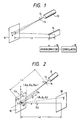
- the most practical method uses a one-dimensional image sensor 15 and a micro-computer 16 as shown in Fig. 1. By this method, a parallel movement of 1 ⁇ m or more and a rotation of the order of 10 ⁇ 5 rad can be measured.
- a laser beam about 1 mm in diameter which is generated by a laser source 12 is applied to a measuring point on an object, through a magnifying lens 14 if necessary, and the one-dimensional image sensor 15 is disposed in the propagating passage of the light beam reflected from the measuring point.
- the beam diameter W on the object 10 and the distance Lo between the object 10 and the image sensor 15 are adjusted so that an average diameter of the speckle pattern is approximately ⁇ Lo/W ( ⁇ : wavelength of the laser beam) on the sensor 15 is larger than the pitch (10 to 20 ⁇ m) of the sensor.
- the axis of the one-dimensional image sensor 15 is adjusted so as to be coincided with the direction of displacement of the speckle pattern which is determined by the optical system and the kind of displacement (the direction of parallel movement, rotation or distortion) of the object.
- the output of the one-dimensional image sensor 15 is subjected to A-D (analog-to-digital) conversion and applied to a micro-computer 16.
- a correlation unit 18 calculates a cross-correlation function between the outputs of the micro-computer which correspond to the speckle patterns before and after the deformation of the object, and the speckle displacement is obtained from the peak positions of the correlation function substantially in real time.
- a method of calculating a "characteristic correlation” has been proposed in the art.
- the output signals of the one-dimensional image sensor 15 are binary-coded with respect of the average thereof.
- the speckle pattern thus obtained has high contrast, so that the peak position is coincided with that of the ordinary cross-correlation function at all times. Accordingly, the speckle displacement can be detected from the extreme position of the cross-correlation function.
- the cross-correlation function is obtained as follows:
- the speckle pattern provided by a scanning operation before the deformation of the object is used as a fixed reference speckle pattern (data) and the speckle pattern provided by a scanning operation while the object is being deformed is utilized as a comparison speckle pattern (data).
- Those data are compared with each other to obtain the cross-correlation function therebetween.
- the speckle pattern provided by a scanning operation while the object is being deformed is employed as a comparison data, but the data obtained by the preceding scanning operation, which is carried out immediately before the present scanning operation for the comparison data, is used as a reference data. That is, the cross-correlation function is obtained while the reference data is renewed every time.
- the speckle pattern to be compared is largely changed with the deformation of the object in comparison with the reference speckle pattern, and therefore the extreme value of the cross-correlation function becomes lower than the unrelated peak values around it, as a result of which it is impossible to obtain the position of the extreme value correctly, and the range of measurement is limited.
- the reference data is identical to the comparison data, so that the position of the extreme value is not moved and the displacement of the object is disregarded. Since this error occurs every scanning operation, the low speed displacement of the speckle pattern cannot be detected particularly when the displacement between two successive scanning operations is less than half of the pitch interval of the image sensor.
- JP-A-62 150 111 From JP-A-62 150 111 it is known that an object will be irradiated by means of a laser beam before and after deformation of the objected is provided. Cross-correlation coefficients of speckle patterns at four observation points before and after the deformation of the object will be stored in an operator. Using these coefficients the amount of deformation of the object is determined.
- An object of this invention is to eliminate the above-described difficulties accompanying a conventional speckle correlation method.
- an object of the invention is to provide a deformation measuring method which is improved in the accuracy of measurement by widening the range of measurement of displacement with no errors.
- Another object of the invention is to provide a deformation measuring method which is improved also in the accuracy of measurement by minimizing the error in measurement of the displacement of an object in the case where the speckle pattern is less changed.
- Still another object of the invention is to provide a deformation measuring device to which the deformation measuring method can be applied.
- the foregoing objects of the invention have been achieved by the provision of deformation measuring method and device in which a part of the surface of an object is irradiated with a laser beam before and after being deformed, thereby obtaining speckle patterns before and after deformation of the object.
- the speckle patterns thus obtained are subjected to photo-electric conversion to provide electrical signals, and the cross-correlation function between the electrical signals is calculated, so that the amount of deformation of the object is determined from the amount of displacement of the speckle pattern which is obtained as the position of the peak value of the cross-correlation function.
- a reference speckle pattern for mutual correlation is renewed, when the peak value of the cross-correlation function becomes lower than a predetermined value, or when the position of the peak value comes out of a predetermined range.
- a reference pattern for the cross-correlation function is renewed, and when displacement of the position of the peak value comes out of a predetermined range, a calculation range for the cross-correlation function is changed.
- a laser beam 13 outputted by a laser source 12 is applied to a measuring region O of an object 10, through a magnifying lens 14 if necessary, and the resultant speckle pattern is observed on an observation plane 30.
- Speckle patterns are formed at the observation point P before and after deformation of the object.
- the output waveform of the image sensor changes as shown in FIG. 3A after and before deformation of the object, the auto-correlation waveform is as shown in FIG 3(B), and the cross-correlation waveform is as shown in FIG. 3(C).
- the reference data (speckle pattern) is fixed or renewed every time to obtain the cross-correlation function
- the reference data (speckle pattern) is renewed in this invention only when the extreme value or a peak-value respectively of the cross-correlation function is lower than a predetermined value or the position of the extreme value comes out of a predetermined range.
- the speckle pattern is displaced greatly with the deformation of the object, the reference pattern is renewed and therefore the range of measurement is not limited.
- the reference speckle pattern is fixed, so that the displacement at a low speed can be detected unlike the conventional method in which the reference data is renewed every time. Accordingly, the accuracy of measurement can be increased while the range of displacement measurement is increased with no errors.
- FIG. 4 shows the arrangement of one example of a deformation measuring device to which the deformation measuring method according to the invention is applied.
- the device as shown in FIG. 4, comprises: a laser source 12 for applying a laser beam 13 to the surface of an object 10 to be measured to form a speckle pattern.
- a laser source 12 for applying a laser beam 13 to the surface of an object 10 to be measured to form a speckle pattern.
- two photosensitive element arrays 20 and 24 are arranged with an angle therebetween.
- each of the photosensitive element arrays has a strip structure in which each of the photosensitive elements (---, 22 n-1 , 22 n , 22 n+1 , ---) constituting a photosensitive element array has a rectangular form with a large ratio of a long side to a short side, (for example, a short side of 13 ⁇ m and a long side of 2.5 mm) which are arranged at intervals of 25 ⁇ m in a strip form.
- the speckle patterns after being subjected to photo-electric conversion by the photosensitive element arrays 20 and 24, are applied to correlators 40 and 42 according to the invention as shown in FIG.4, in each of which the change in position of the extreme value of the cross-correlation function before and after the speckle pattern displacement is detected.
- correlators 40 and 42 are identical in construction, and therefore only the correlator 40 will be described with reference to FIG. 6.
- the correlator 40 as shown in FIG. 6, comprises: a memory 40A for temporarily storing the preceding speckle pattern (one-frame) data of the binary-coded (A/D-converted) electrical signal A which is obtained by the preceding scanning operation through the photosensitive element array 20 as shown in FIG. 4 (in the case of the correlator 42, through the photosensitive element array 24) as shown in FIG. 4; correlation IC 40B (for instance TDC1023 manufactured by TRW Company) for receiving a reference speckle pattern data B from the memory 40A and a comparison speckle pattern data C from the photosensitive element array 20 or 24 (as shown in FIG.
- correlation IC 40B for instance TDC1023 manufactured by TRW Company
- a gate 40C for renewing the reference speckle pattern data B; a maximum value detecting circuit 40D for outputting the extreme value E of the correlation values D provided every shift clock pulse CL, and its timing output F; a counter 40E for receiving the timing output F and the shift clock pulse CL to output a signal G representing the position of the extreme value (in this case, maximum value); and a comparison circuit 40F for comparing the extreme value E outputted from the maximum value detecting circuit 40D with a predetermined threshold value, to output a reference pattern exchange signal H when the extreme value E is less than the threshold value.
- the correlator 40 further comprises: a comparison circuit 40G for comparing the shift of the position G of the extreme value outputted from the counter 40E with a predetermined maximum threshold value for the maximum range, and outputting a reference pattern exchange signal I when the position of the extreme value exceeds the maximum threshold value; a comparison circuit 40H for comparing the shift of the position G of the extreme value with a predetermined minimum threshold value (for the minimum range), and outputting a reference pattern exchange signal J when the position G of the extreme value is less than the minimum threshold value; an Or gate 40I for performing add operation between the reference pattern exchange signals E, I and J and outputting the resultant to the gate 40C and an FIFO (first-in first-out) memory 40J (described later); and the FIFO memory 40J for temporarily storing the position G of the extreme value outputted from the counter 40E and the reference pattern exchange signal H+I+J and applying them to a CPU bus 40K.
- a comparison circuit 40G for comparing the shift of the position G of the extreme value outputted
- the shift of the position of the extreme values detected by the correlators 40 and 42 as shown in FIG. 4 are applied to and processed by the computer 44, in which the amount of deformation of the object is calculated from the amount of displacement of the speckle pattern.
- the computer 44 applies an instruction to the stepping motor controller 46 to move along the x-axis the linear stage 48 on which the object 10 is placed, so that the speckle pattern is displaced along the x-axis, and at the same time applies necessary timing signals to the correlators 40 and 42.
- FIG. 8 is a graph showing the relation between the measured and actual data with the threshold value of the extreme value E set to 100%, 90%, 80%, 70% and 60% in the case where the linear stage 48 as shown in FIG. 4 is moved 6 mm along the x-axis.
- the threshold value of 100% the reference speckle pattern is renewed every time. This is identical to the conventional measurement in which a speckle pattern of the just preceding frame is employed as the reference pattern.
- the threshold value of 60% the reference pattern is not renewed because the threshold value is low. This is substantially identical to the conventional measurement in which the reference pattern is fixed.
- the speckle pattern is moved over the image sensor with small displacement.
- the position of the extreme value is moved. Accordingly, the number of times at which the position of the extreme value comes out of the predetermined range is increased and therefore the number of exchanging the reference pattern of the cross-correlation pattern is greatly increased.
- An exchange of the reference pattern causes an error of the half of the pitch interval of the photosensitive element in the image sensor at maximum, so that the total error corresponding to the product of the pitch interval and the number of exchanging the reference pattern may be caused.
- the following second embodiment is employed: When, in obtaining the cross-correlation function, the extreme value of the cross-correlation function is smaller than a predetermined value, the reference pattern of the mutual-correlation function is renewed; and when the position of the extreme value comes out of the predetermined range, the reference pattern of the cross-correlation function is not renewed, and instead thereof the range of calculation for cross-correlation function is changed (or shifted).
- the frequency of exchanging the reference pattern is decreased and therefore the measurement error can be decreased. Accordingly, in measurement of the displacement of an object when the speckle pattern is less changed, the error is minimized and the accuracy of measurement is increased.
- the deformation measuring device to which the second embodiment of this invention is applied has the same fundamental construction as that in the first embodiment shown in FIG. 4; however, it should be noted that the correlators of the first and second embodiments are greatly different from each other.
- the correlator 40 (or 42) of the second embodiment as shown in FIG. 9, comprises three shift registers (140A, 140B and 140C) for holding reference pattern data B for the binary-coded electrical signal A of the speckle pattern provided by the photosensitive element array 20 (or 24) shown in FIG. 4, for holding comparison data C for calculation of the correlation function with the reference pattern data B, and for holding the binary-coded electrical signal A provided by the photosensitive element array 20 (or 24) during calculation of the correlation function.
- the roles of three shift registers are dynamically swapped for one another by means of a sequencer 140D; that is, the shift registers are used alternately as a reference pattern data shift register, a comparison data shift register, and a buffer shift register.
- the shift register selected for holding the reference pattern data is connected in ring mode by the sequencer 140D, so that the reference pattern data is held for the next correlation calculation.
- the sequencer 140D selects the input of a multiplexer (MPX) 140E to apply one of the outputs of the three shift registers, as the reference pattern data B, to a correlation calculation circuit 140G; and further it selects the input of the other multiplexer (MPX) 140F to apply another of the outputs of the three shift registers, as the comparison data C, to the circuit 140G.
- MPX multiplexer
- the correlation calculation circuit 140G is shown in detail in FIG. 10.
- the circuit 140G comprises: a shift register 140H; an array 140I of, for example, 16 EXCLUSIVE OR circuits; and an array 140J of 16 binary counters, so that sixteen points of the correlation function can be simultaneously calculated.
- a maximum value detecting circuit 140K shown in FIG. 9 receives the values of sixteen points of the correlation function which has been calculated by the correlation calculation circuit 140G, to detect the extreme value of the correlation function and its position E, and outputs them to comparison circuits 140L, 140M and an FIFO (first-in first-out) memory 140N.
- the comparison circuit 140L the extreme value D provided by the maximum value detecting circuit 140K is compared with a predetermined threshold value Dth. When the extreme value D is lower then the threshold value Dth, the comparison circuit 140L applies a reference pattern exchange signal F to the sequencer 140D and the FIFO memory 140N.
- the comparison circuit 140M the position E of the extreme value provided by the maximum value detecting circuit 140K is compared with a predetermined correlation calculation range threshold value H. According to the result of the comparison, the comparison circuit 140M applies a correlation calculation range shift signal I to the sequencer 140D and the FIFO memory 140N to shift the correlation calculation range to the positive side or to the negative side.
- the sequencer 140D In response to the reference pattern exchange signal F, the sequencer 140D causes the roles of the shift registers 140A, 140B and 140C to be exchanged for one another, and changes the selected input terminals of the multiplexers 140E and 140F. In addition, in response to the correlation calculation range shift signal I, the sequencer 140D applies a shift clock pulse to the reference pattern data shift register to shift the correlation calculation range.
- the shifts in the position of the extreme value detected by the correlators 40 and 42 are applied to and processed by the computer 44, and the amount of deformation of the object to be detected is calculated from the amount of displacement of the speckle pattern.
- the computer 44 applies an instruction to the stepping motor controller 46 to move the linear stage 48 along the x-axis on which the object 10 is placed, thereby to displace the speckle pattern along the x-axis, and at the same time applies timing signals to the correlators 40 and 42.
- the photosensitive element arrays 20 and 24 comprising photosensitive elements are in the strip form and each photosensitive element has a rectangular form of a large ratio of a long side to a short side, that is, is in a strip of fancy paper, and further at least two of the photosensitive element arrays are provided.
- the configuration of the photosensitive elements and the number of photosensitive element arrays are not limited only to those in the above-described embodiments.
- the number of photosensitive element arrays to be provided may be only one.
- the provision of more than two photosensitive element arrays will allow the measurement with high accuracy.
Landscapes
- Physics & Mathematics (AREA)
- General Physics & Mathematics (AREA)
- Length Measuring Devices By Optical Means (AREA)
Claims (10)
- Procédé de mesure de déformation destiné à détecter la valeur de déformation d'un objet à partir d'un déplacement d'un motif moucheté de l'objet, comprenant les étapes de :
irradiation de l'objet avec un faisceau laser avant et après déformation de l'objet afin d'obtenir des motifs mouchetés ;
conversion des motifs mouchetés en signaux électriques ;
calcul d'une fonction de corrélation croisée entre les motifs mouchetés à partir des signaux électriques ; et
utilisation de la fonction de corrélation croisée pour déterminer la valeur de la déformation de l'objet,
dans lequel ladite étape de calcul comprend l'étape de comparaison de données de motif moucheté de comparaison à des données de motif moucheté de référence pour obtenir la fonction de corrélation croisée et de remplacement des données de motif moucheté de référence ;
caractérisé par les étapes suivantes :
obtention de la valeur de pic de la fonction de corrélation croisée ;
obtention de la valeur de décalage de position de la valeur de pic de la fonction de corrélation croisée afin de déterminer la valeur de la déformation de l'objet ; et par la fait que
ladite étape de calcul comprend le remplacement du motif moucheté de référence lorsque la valeur de pic de corrélation croisée est inférieure en niveau à une valeur prédéterminée. - Procédé de mesure de déformation selon la revendication 1, dans lequel lesdites données de motif moucheté de référence remplacées comprennent des données de motif moucheté obtenues au moyen de l'opération de balayage qui précède immédiatement l'opération de balayage courante qui produit les données de motif moucheté de comparaison.
- Procédé de mesure de déformation selon la revendication 1, dans lequel ladite étape de calcul comprend en outre l'étape de remplacement des données de motif moucheté de référence lorsque la position de la valeur de pic de la fonction de corrélation croisée tombe à l'extérieur d'une plage prédéterminée.
- Procédé de mesure de déformation selon la revendication 3, dans lequel ladite plage prédéterminée a pour valeur minimale une valeur qui correspond à un intervalle d'un demi-pas d'un réseau d'éléments photo-sensibles prévu pour effectuer ladite étape de conversion.
- Procédé de mesure de déformation selon la revendication 1, dans lequel ladite étape de calcul comprend en outre l'étape de décalage de la plage de calcul pour obtenir la fonction de corrélation croisée lorsque la position de la valeur de pic de la fonction de corrélation croisée tombe à l'extérieur d'une plage prédéterminée.
- Procédé de mesure de déformation selon la revendication 5, dans lequel ladite étape de décalage comprend l'étape de décalage de la plage de calcul au niveau d'un côté positif ou d'un côté négatif de celle-ci.
- Dispositif de mesure de déformation destiné à détecter la valeur d'une déformation d'un objet à partir d'un déplacement d'un motif moucheté de l'objet, comprenant :
une source de lumière (12) pour irradier l'objet (10) avec un faisceau laser (13) afin d'obtenir des motifs mouchetés avant et après déformation de l'objet (10) ;
au moins un réseau d'éléments photosensibles (20 ; 24) comprenant plusieurs éléments photosensibles pour convertir les motifs mouchetés de l'objet (10) en signaux électriques correspondants ; et
au moins un corrélateur (40 ; 42) pour calculer la fonction de corrélation croisée entre les motifs mouchetés à partir des signaux électriques ;
caractérisé en ce que :
ledit corrélateur (40 ; 42) est prévu pour obtenir la position de la valeur de pic de la fonction de corrélation croisée ;
ledit corrélateur (40 ; 42) est en outre prévu pour remplacer les données de motif moucheté de référence lorsque la valeur de pic est inférieure en niveau à une valeur prédéterminée ou lorsque la valeur de pic tombe à l'extérieur de la plage prédéterminée ; et
un microcalculateur (44) est prévu pour obtenir la valeur du décalage en position de la valeur de pic (E) de la fonction de corrélation croisée et pour déterminer la valeur de la déformation de l'objet (10) à partir de la valeur du décalage. - Dispositif de mesure de déformation selon la revendication 7, caractérisé en ce que ledit corrélateur (40 ; 42) comprend un moyen de mémoire (40A) pour stocker temporairement les données de motif moucheté précédent, un moyen de calcul de corrélation (40B) pour recevoir des données de motif moucheté de référence (B) en provenance de ladite mémoire (40A) et des données de motif moucheté de comparaison (C) en provenance dudit réseau d'éléments photosensibles (20 ; 24) et pour émettre en sortie les valeurs de corrélation (D) entre les données de motif moucheté de référence et les données de motif moucheté de comparaison (B, C), un circuit de détection de valeur maximale (40D) pour émettre en sortie la valeur de pic (E) des valeurs de corrélation (D), un moyen de comparaison (40F, 40G, 40H) pour comparer le niveau de la valeur de pic (E) et sa position respectivement à une valeur prédéterminée et à une plage prédéterminée et pour émettre en sortie un signal d'instruction (H, I, J) destiné à remplacer les données de motif moucheté de référence (B) lorsque la valeur de pic (E) est inférieure en niveau à la valeur prédéterminée ou lorsque la position de la valeur de pic (E) tombe à l'extérieur de la plage prédéterminée, et une porte (40C) pour remplacer les données de motif moucheté de référence (B) par les données de motif moucheté précédent en réponse au signal d'instruction.
- Dispositif de mesure de déformation selon la revendication 7, caractérisé en ce que ledit corrélateur (40 ; 42) comprend trois registres à décalage (140A, 140B, 140C) destinés à servir de premier registre à décalage pour bloquer les signaux électriques en tant que données de motif moucheté de référence, de second registre à décalage pour bloquer les signaux électriques en tant que données de motif moucheté de comparaison, et de registre à décalage tampon pour bloquer les signaux électriques pendant le calcul de la fonction de corrélation croisée, lesdits trois registres à décalage (140A, 140B, 140C) étant dynamiquement accédés par passage de l'un à l'autre, un premier multiplexeur (140E) pour recevoir des signaux de sortie en provenance desdits registres à décalage (140A, 140B, 140C) et pour émettre en sortie l'un des signaux de sortie en tant que données de motif moucheté de référence (B) et un second multiplexeur (140F) pour recevoir des signaux de sortie en provenance desdits registres à décalage (140A, 140B, 140C) et pour émettre en sortie l'un des signaux de sortie en tant que données de motif moucheté de comparaison (C), un circuit de calcul de corrélation (140G) pour recevoir les données de motif moucheté de référence et les données de motif moucheté de comparaison (B, C) en provenance desdits premier et second multiplexeurs (140E, 140F) et pour calculer la fonction de corrélation croisée entre elles, un circuit de détection de valeur maximale (140K) pour obtenir la valeur de pic de la fonction de corrélation croisée et sa position, un premier circuit de comparaison (140L) pour comparer la valeur de pic à une valeur prédéterminée (D-ième) et pour émettre en sortie un premier signal d'instruction pour remplacer les données de motif moucheté de référence (B) lorsque la valeur de pic est inférieure du point de vue du niveau à la valeur prédéterminée (D-ième), un second circuit de comparaison (140M) pour comparer la position de la valeur de pic par rapport à une plage prédéterminée (H) et pour émettre en sortie un second signal d'instruction pour décaler la plage de corrélation croisée en vue du calcul de la fonction de corrélation croisée lorsque la position de la valeur de pic tombe à l'extérieur de la plage prédéterminée (H) et un contrôleur de séquence (140D) pour permuter les fonctions desdits trois registres à décalage (140A, 140B, 140C) et pour modifier les bornes d'entrée sélectionnées desdits premier et second multiplexeurs (140E, 140F) en réponse auxdits premier et second signaux d'instruction pour ainsi remplacer les données de motif moucheté de référence (B) et décaler la plage de calcul de corrélation croisée.
- Dispositif de mesure de déformation selon l'une quelconque des revendications 7 à 9, dans lequel ledit réseau d'éléments photosensibles (20, 24) présente une forme rectangulaire dont le rapport longueur sur largeur est grand.
Applications Claiming Priority (4)
| Application Number | Priority Date | Filing Date | Title |
|---|---|---|---|
| JP15429888A JPH0629703B2 (ja) | 1988-06-22 | 1988-06-22 | 変形の測定方法 |
| JP154298/88 | 1988-06-22 | ||
| JP17835288A JPH0629704B2 (ja) | 1988-07-18 | 1988-07-18 | 変形の測定方法 |
| JP178352/88 | 1988-07-18 |
Publications (3)
| Publication Number | Publication Date |
|---|---|
| EP0347912A2 EP0347912A2 (fr) | 1989-12-27 |
| EP0347912A3 EP0347912A3 (en) | 1990-07-04 |
| EP0347912B1 true EP0347912B1 (fr) | 1993-02-24 |
Family
ID=26482622
Family Applications (1)
| Application Number | Title | Priority Date | Filing Date |
|---|---|---|---|
| EP89111389A Expired - Lifetime EP0347912B1 (fr) | 1988-06-22 | 1989-06-22 | Procédé de mesure de déformations et appareil utilisant la fonction de corrélation croisée entre images-speckle |
Country Status (3)
| Country | Link |
|---|---|
| US (1) | US4967093A (fr) |
| EP (1) | EP0347912B1 (fr) |
| DE (1) | DE68904993T2 (fr) |
Families Citing this family (34)
| Publication number | Priority date | Publication date | Assignee | Title |
|---|---|---|---|---|
| FR2670282B1 (fr) * | 1990-12-10 | 1994-04-01 | Cachan Labo Meca Techn Ecole Nor | Procede de mesure de champ de deplacement. |
| DE4039972A1 (de) * | 1990-12-14 | 1992-06-17 | Man Technologie Gmbh | Verfahren und einrichtung zur erfassung der oberflaechendeformation von bauteilen mittels elektronischer speckle-interferometrie |
| JPH074928A (ja) * | 1993-06-15 | 1995-01-10 | Shimadzu Corp | 歪測定装置 |
| US6097477A (en) * | 1994-05-27 | 2000-08-01 | American Research Corporation Of Virginia | Laser speckle strain and deformation sensor using linear array image cross-correlation method for specifically arranged triple-beam triple-camera configuration |
| JP2692599B2 (ja) * | 1994-07-27 | 1997-12-17 | 株式会社島津製作所 | レーザー非接触伸び計 |
| WO1997000482A1 (fr) * | 1995-06-15 | 1997-01-03 | The Regents Of The University Of Michigan | Procede et appareil de composition et d'affichage d'une image tridimensionnelle a partir de donnees bidimensionnelles d'exploration aux ultrasons |
| JPH10185526A (ja) * | 1996-12-27 | 1998-07-14 | Japan Atom Energy Res Inst | 非接触歪み計 |
| US6642506B1 (en) | 2000-06-01 | 2003-11-04 | Mitutoyo Corporation | Speckle-image-based optical position transducer having improved mounting and directional sensitivities |
| US6873422B2 (en) | 2000-12-08 | 2005-03-29 | Mitutoyo Corporation | Systems and methods for high-accuracy displacement determination in a correlation based position transducer |
| DE10110969B4 (de) * | 2001-03-07 | 2004-02-12 | Carl v. Ossietzky Universität Oldenburg, vertreten durch den Kanzler | Verfahren zur Erfassung von out-of-plane-Oberflächenverformungen |
| US7065258B2 (en) * | 2001-05-21 | 2006-06-20 | Mitutoyo Corporation | Systems and methods for reducing accumulated systematic errors in image correlation displacement sensing systems |
| US6996291B2 (en) * | 2001-08-06 | 2006-02-07 | Mitutoyo Corporation | Systems and methods for correlating images in an image correlation system with reduced computational loads |
| GB2383411B (en) * | 2001-08-06 | 2005-11-09 | Mitutoyo Corp | Systems and methods for correlating images in an image correlation system with reduced computational loads |
| US6990254B2 (en) | 2001-08-06 | 2006-01-24 | Mitutoyo Corporation | Systems and methods for correlating images in an image correlation system with reduced computational loads |
| US7085431B2 (en) | 2001-11-13 | 2006-08-01 | Mitutoyo Corporation | Systems and methods for reducing position errors in image correlation systems during intra-reference-image displacements |
| CN1244044C (zh) * | 2003-01-20 | 2006-03-01 | 张宏志 | 一种鼠标光学信号处理方法 |
| US6937349B2 (en) * | 2003-05-02 | 2005-08-30 | Mitutoyo Corporation | Systems and methods for absolute positioning using repeated quasi-random pattern |
| US7773070B2 (en) * | 2004-05-21 | 2010-08-10 | Cypress Semiconductor Corporation | Optical positioning device using telecentric imaging |
| US7295324B2 (en) * | 2004-07-13 | 2007-11-13 | Mitutoyo Corporation | System and method for improving accuracy in a speckle-based image correlation displacement sensor |
| JP2007170955A (ja) * | 2005-12-21 | 2007-07-05 | Nagasaki Univ | 変位/ひずみ計測方法及び変位/ひずみ計測装置 |
| US9582883B2 (en) * | 2006-06-16 | 2017-02-28 | Lyle G. Shirley | Method and apparatus for remote sensing and comparing utilizing radiation speckle |
| US8073287B1 (en) * | 2007-02-26 | 2011-12-06 | George Mason Intellectual Properties, Inc. | Recognition by parts using adaptive and robust correlation filters |
| US20100287083A1 (en) * | 2007-12-28 | 2010-11-11 | Mastercard International, Inc. | Detecting modifications to financial terminals |
| RU2403536C1 (ru) * | 2009-04-13 | 2010-11-10 | Учреждение Российской Академии Наук Институт Физики Прочности И Материаловедения Сибирского Отделения Ран (Ифпм Со Ран) | Способ отображения зон локализации деформации поверхности |
| US8600147B2 (en) | 2009-06-03 | 2013-12-03 | The United States of America as represented by the Secreatary of the Navy | System and method for remote measurement of displacement and strain fields |
| WO2012147495A1 (fr) * | 2011-04-28 | 2012-11-01 | 三洋電機株式会社 | Dispositif d'acquisition d'informations et dispositif de détection d'objet |
| WO2013019992A1 (fr) | 2011-08-02 | 2013-02-07 | The Government Of The United States Of America, As Represented By The Secretary Of The Navy | Système et procédé de mesures tridimensionnelles de déplacement et de contrainte plein champ à distance |
| US9311566B2 (en) | 2012-08-03 | 2016-04-12 | George Mason Research Foundation, Inc. | Method and system for direct strain imaging |
| DE102014108643B3 (de) | 2014-06-19 | 2015-06-25 | Lavision Gmbh | Verfahren zur Ermittlung eines räumlichen Verschiebungsvektorfeldes |
| AT517150B1 (de) * | 2015-04-23 | 2018-02-15 | Ait Austrian Inst Tech Gmbh | Inspektion mit Polarisationsfiltern |
| JP6619823B2 (ja) * | 2015-06-04 | 2019-12-11 | ルーミンコード エーエス | 自由空間位置ファインダー |
| CN110307785B (zh) * | 2019-07-11 | 2020-08-21 | 清华大学 | 基于记忆效应的光斑位置精准定位的方法、装置及系统 |
| US11391563B2 (en) * | 2020-02-06 | 2022-07-19 | Purdue Research Foundation | Ultra-sensitive speckle analyzing system |
| JP7679224B2 (ja) * | 2021-04-28 | 2025-05-19 | キヤノン株式会社 | 変位計及び物品の製造方法 |
Family Cites Families (9)
| Publication number | Priority date | Publication date | Assignee | Title |
|---|---|---|---|---|
| US3617625A (en) * | 1969-04-28 | 1971-11-02 | Itek Corp | Image correlation system |
| WO1987007365A1 (fr) * | 1986-05-23 | 1987-12-03 | Vachon Reginald I | Appareil et procede permettant de determiner la contrainte et la deformation dans des conduites, des enceintes sous pression, des elements de structure et autres corps deformables |
| JPS5952963A (ja) * | 1982-09-20 | 1984-03-27 | Toshiba Corp | 走査装置 |
| US4539651A (en) * | 1983-02-09 | 1985-09-03 | Ludman Jacques E | Optical correlator |
| US4657393A (en) * | 1983-12-29 | 1987-04-14 | Robotic Vision Systems, Inc. | Pattern optimization when measuring depth to a surface using lens focusing |
| US4641972A (en) * | 1984-09-14 | 1987-02-10 | New York Institute Of Technology | Method and apparatus for surface profilometry |
| US4636069A (en) * | 1984-11-15 | 1987-01-13 | Matrix Instruments Inc. | Method for reading deformation images on electrophotographic media |
| US4678920A (en) * | 1985-06-17 | 1987-07-07 | General Motors Corporation | Machine vision method and apparatus |
| JPH0615968B2 (ja) * | 1986-08-11 | 1994-03-02 | 伍良 松本 | 立体形状測定装置 |
-
1989
- 1989-06-19 US US07/367,659 patent/US4967093A/en not_active Expired - Lifetime
- 1989-06-22 EP EP89111389A patent/EP0347912B1/fr not_active Expired - Lifetime
- 1989-06-22 DE DE8989111389T patent/DE68904993T2/de not_active Expired - Fee Related
Also Published As
| Publication number | Publication date |
|---|---|
| EP0347912A2 (fr) | 1989-12-27 |
| US4967093A (en) | 1990-10-30 |
| DE68904993T2 (de) | 1993-06-17 |
| DE68904993D1 (de) | 1993-04-01 |
| EP0347912A3 (en) | 1990-07-04 |
Similar Documents
| Publication | Publication Date | Title |
|---|---|---|
| EP0347912B1 (fr) | Procédé de mesure de déformations et appareil utilisant la fonction de corrélation croisée entre images-speckle | |
| US6151118A (en) | Three-dimensional measuring system and method of measuring the shape of an object | |
| EP0181553B1 (fr) | Détecteur d'images à trois dimensions | |
| US5319442A (en) | Optical inspection probe | |
| US7587094B2 (en) | Phase measurement system | |
| US5311599A (en) | Method and apparatus for optical testing of samples | |
| JPS6184515A (ja) | 対象物上の複数の点までの距離を求める方法及び装置 | |
| KR20130032368A (ko) | 삼차원 계측장치, 삼차원 계측방법 및 기억매체 | |
| US5329458A (en) | Device and method for detecting position of edge of cutting tool | |
| EP0302512B1 (fr) | Calibration simplifiée pour un dispositif d'obtention d'information à distance | |
| US4682041A (en) | Coating quality measuring device and method | |
| JPH09113223A (ja) | 非接触距離姿勢測定方法及び装置 | |
| EP0347911B1 (fr) | Procédé de mesure de déformations et appareil utilisant un réseau d'éléments photo-électriques | |
| US20020005956A1 (en) | Method and device for measuring three-dimensional position | |
| US5600123A (en) | High-resolution extended field-of-view tracking apparatus and method | |
| Gruen et al. | Real-time photogrammetry at the digital photogrammetric station (DIPS) of ETH Zurich | |
| JPH0635921B2 (ja) | スペックル測長計 | |
| JPH0629703B2 (ja) | 変形の測定方法 | |
| EP0157431A1 (fr) | Procédé de mesure d'un corps en mouvement dans un espace en trois dimensions et appareil optoélectronique pour la mise en oeuvre d'un tel procédé | |
| JPH0629704B2 (ja) | 変形の測定方法 | |
| JP3463967B2 (ja) | 測距装置と方法 | |
| JP2946381B2 (ja) | 表面粗さ測定方法及び装置 | |
| JP2941007B2 (ja) | スペックル測長計 | |
| JPS5861436A (ja) | 投影型mtf測定装置の受光素子 | |
| JPH0933248A (ja) | パッシブ三角測量式距離計 |
Legal Events
| Date | Code | Title | Description |
|---|---|---|---|
| PUAI | Public reference made under article 153(3) epc to a published international application that has entered the european phase |
Free format text: ORIGINAL CODE: 0009012 |
|
| AK | Designated contracting states |
Kind code of ref document: A2 Designated state(s): DE GB |
|
| PUAL | Search report despatched |
Free format text: ORIGINAL CODE: 0009013 |
|
| AK | Designated contracting states |
Kind code of ref document: A3 Designated state(s): DE GB |
|
| 17P | Request for examination filed |
Effective date: 19900608 |
|
| 17Q | First examination report despatched |
Effective date: 19910606 |
|
| GRAA | (expected) grant |
Free format text: ORIGINAL CODE: 0009210 |
|
| AK | Designated contracting states |
Kind code of ref document: B1 Designated state(s): DE GB |
|
| REF | Corresponds to: |
Ref document number: 68904993 Country of ref document: DE Date of ref document: 19930401 |
|
| PLBE | No opposition filed within time limit |
Free format text: ORIGINAL CODE: 0009261 |
|
| STAA | Information on the status of an ep patent application or granted ep patent |
Free format text: STATUS: NO OPPOSITION FILED WITHIN TIME LIMIT |
|
| 26N | No opposition filed | ||
| REG | Reference to a national code |
Ref country code: GB Ref legal event code: IF02 |
|
| PGFP | Annual fee paid to national office [announced via postgrant information from national office to epo] |
Ref country code: GB Payment date: 20040616 Year of fee payment: 16 |
|
| PGFP | Annual fee paid to national office [announced via postgrant information from national office to epo] |
Ref country code: DE Payment date: 20040701 Year of fee payment: 16 |
|
| PG25 | Lapsed in a contracting state [announced via postgrant information from national office to epo] |
Ref country code: GB Free format text: LAPSE BECAUSE OF NON-PAYMENT OF DUE FEES Effective date: 20050622 |
|
| PG25 | Lapsed in a contracting state [announced via postgrant information from national office to epo] |
Ref country code: DE Free format text: LAPSE BECAUSE OF NON-PAYMENT OF DUE FEES Effective date: 20060103 |
|
| GBPC | Gb: european patent ceased through non-payment of renewal fee |
Effective date: 20050622 |