EP0347872B1 - Dispositif d'aération pour un réservoir d'huile fabriqué de préférence en matière plastique - Google Patents
Dispositif d'aération pour un réservoir d'huile fabriqué de préférence en matière plastique Download PDFInfo
- Publication number
- EP0347872B1 EP0347872B1 EP89111272A EP89111272A EP0347872B1 EP 0347872 B1 EP0347872 B1 EP 0347872B1 EP 89111272 A EP89111272 A EP 89111272A EP 89111272 A EP89111272 A EP 89111272A EP 0347872 B1 EP0347872 B1 EP 0347872B1
- Authority
- EP
- European Patent Office
- Prior art keywords
- tank
- oil
- filter
- connecting piece
- wall
- Prior art date
- Legal status (The legal status is an assumption and is not a legal conclusion. Google has not performed a legal analysis and makes no representation as to the accuracy of the status listed.)
- Expired - Lifetime
Links
- 229920003023 plastic Polymers 0.000 title claims description 5
- 239000004033 plastic Substances 0.000 title claims description 5
- 238000009423 ventilation Methods 0.000 claims description 4
- 230000014759 maintenance of location Effects 0.000 description 16
- 239000000945 filler Substances 0.000 description 4
- 238000011144 upstream manufacturing Methods 0.000 description 3
- 238000000034 method Methods 0.000 description 2
- 230000000717 retained effect Effects 0.000 description 2
- 238000001914 filtration Methods 0.000 description 1
- 239000002184 metal Substances 0.000 description 1
- 230000000149 penetrating effect Effects 0.000 description 1
- 238000013022 venting Methods 0.000 description 1
Images


Classifications
-
- F—MECHANICAL ENGINEERING; LIGHTING; HEATING; WEAPONS; BLASTING
- F15—FLUID-PRESSURE ACTUATORS; HYDRAULICS OR PNEUMATICS IN GENERAL
- F15B—SYSTEMS ACTING BY MEANS OF FLUIDS IN GENERAL; FLUID-PRESSURE ACTUATORS, e.g. SERVOMOTORS; DETAILS OF FLUID-PRESSURE SYSTEMS, NOT OTHERWISE PROVIDED FOR
- F15B1/00—Installations or systems with accumulators; Supply reservoir or sump assemblies
- F15B1/26—Supply reservoir or sump assemblies
-
- B—PERFORMING OPERATIONS; TRANSPORTING
- B01—PHYSICAL OR CHEMICAL PROCESSES OR APPARATUS IN GENERAL
- B01D—SEPARATION
- B01D35/00—Filtering devices having features not specifically covered by groups B01D24/00 - B01D33/00, or for applications not specifically covered by groups B01D24/00 - B01D33/00; Auxiliary devices for filtration; Filter housing constructions
- B01D35/02—Filters adapted for location in special places, e.g. pipe-lines, pumps, stop-cocks
- B01D35/027—Filters adapted for location in special places, e.g. pipe-lines, pumps, stop-cocks rigidly mounted in or on tanks or reservoirs
- B01D35/0276—Filtering elements with a vertical rotation or symmetry axis mounted on tanks or reservoirs
-
- B—PERFORMING OPERATIONS; TRANSPORTING
- B01—PHYSICAL OR CHEMICAL PROCESSES OR APPARATUS IN GENERAL
- B01D—SEPARATION
- B01D36/00—Filter circuits or combinations of filters with other separating devices
- B01D36/001—Filters in combination with devices for the removal of gas, air purge systems
-
- F—MECHANICAL ENGINEERING; LIGHTING; HEATING; WEAPONS; BLASTING
- F15—FLUID-PRESSURE ACTUATORS; HYDRAULICS OR PNEUMATICS IN GENERAL
- F15B—SYSTEMS ACTING BY MEANS OF FLUIDS IN GENERAL; FLUID-PRESSURE ACTUATORS, e.g. SERVOMOTORS; DETAILS OF FLUID-PRESSURE SYSTEMS, NOT OTHERWISE PROVIDED FOR
- F15B21/00—Common features of fluid actuator systems; Fluid-pressure actuator systems or details thereof, not covered by any other group of this subclass
- F15B21/04—Special measures taken in connection with the properties of the fluid
- F15B21/044—Removal or measurement of undissolved gas, e.g. de-aeration, venting or bleeding
Definitions
- the invention relates to a ventilation device on an oil tank, preferably made of plastic, with an oil return filter attached to a tank opening, the oil return filter having an expansion chamber connected to the outside atmosphere in the area of the tank opening and an annular oil retention chamber connected upstream of the expansion chamber towards the inside of the tank.
- An oil return filter with an expansion chamber is known from DE-B-1941 153.
- the expansion chamber of this filter was further improved by providing an oil retention space upstream of it, which was arranged between the outer wall of the filter and the inner wall of an additional sleeve surrounding the filter. This reliably ensures that entrained oil is retained in the retention space and in the expansion chamber when the filter is vented and does not escape into the open.
- the invention has for its object to simplify a generic ventilation device compared to the known prior art and to adapt it in particular to an oil tank made of plastic.
- a tank neck in the form of a cylindrical sleeve is provided at the tank opening, the outer region of which, together with a housing of the filter, forms the expansion chamber in that the oil retention space is formed between an outer wall of the oil return filter and the inner wall of the tank neck that the tank neck has at its end facing the tank interior a lip directed inwards towards the oil return filter, which separates the oil retention chamber from the tank interior, and that one or more small passage openings are provided for the passage of air from the tank interior into the oil retention room.
- the configuration and arrangement according to the invention ensure that a part of the tank neck itself is used for delimiting the expansion chamber and the oil retention space, this part constantly remaining on the tank.
- the remaining limits of the expansion chamber and oil retention space are formed in a simple manner on the oil return filter itself.
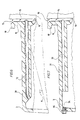
- an oil return filter 1 is arranged at the tank opening 2 of an oil tank 3.
- the tank 3 is preferably made of plastic and is produced in a centrifugal process. Basically, the tank 3 can also consist of metal.
- the oil return filter 1 comprises, in a known manner, an oil return nozzle 5 via which the oil flows back into the tank 3 after appropriate filtering.
- the oil level in the tank is indicated by the arrowhead 6.
- the displaced air escapes via an air filter 7 known per se on the oil return filter 1.
- the following measures are taken in the illustrated oil return filter and the tank: at the tank opening there is a fixed, preferably one-piece, filler neck 8 in the form of a cylinder sleeve.
- the tank neck 8 is interspersed with the interposition of a seal 9 from an outer housing 11 of the oil return filter 1 such that an expansion chamber 12 is formed in the outer region of the neck, from which air flowing in from the interior of the tank can expand via the filter 7 to the outside.
- the expansion chamber has baffles in a manner known per se, from which entrained oil is retained. Such baffles are known per se, so that they do not need to be described in detail here.
- annular oil retention space 15 is formed, which is upstream of the expansion chamber 12 in terms of flow.
- the filler neck 8 has a lip 16, which is directed in a ring inward towards the wall 13 of the oil return filter 1 and separates the oil retention space 15 from the inside of the tank.
- the lip 16 does not rest on the wall 13 of the filter.
- a small annular gap 17 thus remains between the lip 16 and the wall 13 for air.
- the housing 11 of the filter 1 is connected to the tank neck 8 by a bayonet lock.
- the filler neck 8 has at its outer end at an angular interval of 90 ° four outwardly directed tabs 18 which cooperate in a known manner with corresponding tabs 19 projecting inwardly from the housing 11.
- the oil return filter 1 is inserted with the housing 11 by pressing onto the seal so that the tabs 19 are initially in the space between the tabs 18. Subsequently the filter 1 is rotated by 90 °, the tabs 19 engaging under the tabs 18 and the filter 1 is held securely on the tank 3 by the bayonet lock thus imparted.
- a screw 22 which can be screwed in is arranged in a lateral projection 21 of the filter housing 11; whose downward shaft forms a locking pin 24.
- the screw 22 is screwed in so far that the locking pin 24 engages in a recess 25 formed next to the tank neck 8 and thereby secures the bayonet catch against rotation.
- the bayonet lock can therefore only be opened again when the pin 24 has been unscrewed from the recess 25.
- FIG. 4 shows a modified embodiment of the filler neck 8.
- the annular lip 16 projects so far inwards that it lies against the outer wall 13 of the filter.
- two small passage openings 26 are formed directly on the tank neck 8.
- the inner wall of the tank neck 8 has inwardly directed towards the wall 13 of the filter, annular projections, which represent baffles 27 for entrained oil.
- the lip 16 also bears on the outer wall 13 of the filter.
- one or more passage openings 28 are formed directly in the area of the lip 16.
- a pipe 32 (in the course of the centrifugal process) is let into an upper wall 31 of the tank 3, on which the tank neck 8 is formed, and is connected on the one hand to the oil retention space 15 and on the other hand to the inside of the tank.
- the lip 16 of the tank neck 8 again lies tightly against the outer wall 13 of the filter. If the oil level 6 in the tank 3 assumes the inclined position shown, air can still escape through the pipe 32 into the oil retention space without oil directly penetrating into this space.
- FIG. 7 works in the same way. There, however, the tube is replaced by a bore 33 in the correspondingly thickened wall 31, which is subsequently produced via an additional bore 34 with a correspondingly long drill. The bore 34 is then sealed with a screw 35.
Landscapes
- Chemical & Material Sciences (AREA)
- Engineering & Computer Science (AREA)
- Chemical Kinetics & Catalysis (AREA)
- Physics & Mathematics (AREA)
- Fluid Mechanics (AREA)
- Mechanical Engineering (AREA)
- General Engineering & Computer Science (AREA)
- Analytical Chemistry (AREA)
- Lubrication Details And Ventilation Of Internal Combustion Engines (AREA)
- Supply Devices, Intensifiers, Converters, And Telemotors (AREA)
Claims (8)
Applications Claiming Priority (2)
| Application Number | Priority Date | Filing Date | Title |
|---|---|---|---|
| DE3821331A DE3821331C2 (de) | 1988-06-24 | 1988-06-24 | Lüftungseinrichtung für einen vorzugsweise aus Kunststoff gefertigten Öltank |
| DE3821331 | 1988-06-24 |
Publications (2)
| Publication Number | Publication Date |
|---|---|
| EP0347872A1 EP0347872A1 (fr) | 1989-12-27 |
| EP0347872B1 true EP0347872B1 (fr) | 1991-01-16 |
Family
ID=6357160
Family Applications (1)
| Application Number | Title | Priority Date | Filing Date |
|---|---|---|---|
| EP89111272A Expired - Lifetime EP0347872B1 (fr) | 1988-06-24 | 1989-06-21 | Dispositif d'aération pour un réservoir d'huile fabriqué de préférence en matière plastique |
Country Status (3)
| Country | Link |
|---|---|
| EP (1) | EP0347872B1 (fr) |
| DE (1) | DE3821331C2 (fr) |
| FI (1) | FI93196C (fr) |
Families Citing this family (5)
| Publication number | Priority date | Publication date | Assignee | Title |
|---|---|---|---|---|
| DE4310234C1 (de) * | 1993-03-30 | 1994-08-18 | Argo Feinmechanik | Rücklauffilter für Flüssigkeiten |
| DE29701824U1 (de) * | 1997-02-03 | 1997-03-27 | Still GmbH, 22113 Hamburg | Tankanordnung |
| FI3649U1 (fi) * | 1998-06-01 | 1998-10-09 | Hydrox Pipeline Ltd | Esisuodatusyksikkö |
| DE102008061283A1 (de) | 2008-12-11 | 2010-07-15 | Innovatun Gmbh | Be- und Entlüftungsventil, Brennfluidtank mit einem solchen Ventil und Verfahren zur Be- und Entlüftung eines Brennfluidtanks |
| CN111795017A (zh) * | 2020-07-06 | 2020-10-20 | 东风汽车股份有限公司 | 一种转向油罐 |
Family Cites Families (2)
| Publication number | Priority date | Publication date | Assignee | Title |
|---|---|---|---|---|
| US3288289A (en) * | 1964-10-12 | 1966-11-29 | Rosaen Filter Co | Mobile filter with contaminant collecting means |
| DE1941153B2 (de) * | 1969-08-13 | 1970-10-01 | Argo Feinmechanik | Be- und Entlueftungseinrichtung fuer einen OElbehaelter |
-
1988
- 1988-06-24 DE DE3821331A patent/DE3821331C2/de not_active Expired - Fee Related
-
1989
- 1989-06-21 EP EP89111272A patent/EP0347872B1/fr not_active Expired - Lifetime
- 1989-06-22 FI FI893087A patent/FI93196C/fi not_active IP Right Cessation
Also Published As
| Publication number | Publication date |
|---|---|
| FI893087A0 (fi) | 1989-06-22 |
| FI893087A (fi) | 1989-12-25 |
| FI93196B (fi) | 1994-11-30 |
| DE3821331A1 (de) | 1989-12-28 |
| DE3821331C2 (de) | 1996-08-08 |
| EP0347872A1 (fr) | 1989-12-27 |
| FI93196C (fi) | 1995-03-10 |
Similar Documents
| Publication | Publication Date | Title |
|---|---|---|
| EP0395841B1 (fr) | Ouverture de remplissage pour le remplissage de l'huile de lubrification dans un moteur à combustion interne | |
| EP1174597B1 (fr) | Ensemble pour un moteur à combustion avec un filtre à huile | |
| DE2125117C3 (fr) | ||
| DE3814683A1 (de) | Siebdeckel fuer einen reinigungseinsatz in einer wasseraufbereitungsvorrichtung mit einem hohlrohr | |
| DE102004003438A1 (de) | Fließbecher für eine Farbspritzpistole | |
| DE2355064A1 (de) | Anschlussvorrichtung mit absperrmittel | |
| DE2346286C3 (de) | Vorrichtung zur Gasabscheidung | |
| DE202018101974U1 (de) | Basiskörper für eine Wasserpfeife | |
| DE202004003116U1 (de) | Fließbecher für eine Farbspritzpistole | |
| EP0347872B1 (fr) | Dispositif d'aération pour un réservoir d'huile fabriqué de préférence en matière plastique | |
| DE3206965C2 (fr) | ||
| DE3201217C2 (de) | Be- und Entlüftungseinrichtung für ein Getriebegehäuse, insbesondere ein Motorrad-Kardangehäuse | |
| DE3341675C1 (de) | Sicherheitsverschluss fuer zweiteilige Gehaeuse zum Filtern von Fluessigkeiten | |
| DE102019132227A1 (de) | Entlüftungseinheit mit Gewindeabschnitt | |
| DE8906695U1 (de) | Cerumen-Schutzkappe | |
| DE19602819B4 (de) | Kraftstoffbehälter | |
| DE4221263C2 (de) | Pipettierhilfe | |
| DE2014832A1 (de) | Rohrverbindung | |
| DE19900472C1 (de) | Ventil zum Entlüften, Befüllen oder Entleeren insbesondere für Heizkörper oder Heizanlagen | |
| DE19653515C2 (de) | Vorrichtung zum Einfüllen und Abscheiden von Schmieröl an einer Brennkraftmaschine | |
| DE29900221U1 (de) | Entlüftungsvorrichtung mit einem Entlüftungsventil, insbesondere für Heizkörper | |
| DE9112555U1 (de) | Vorrichtung zur Entlüftung von Maschinengehäusen | |
| DE3886252T3 (de) | Leuchte mit einer wasserdichten Belüftungsöffnung. | |
| DE8324849U1 (de) | Verschluss fuer einen Tank | |
| EP2037154B1 (fr) | Dispositif d'aération pour un boîtier |
Legal Events
| Date | Code | Title | Description |
|---|---|---|---|
| PUAI | Public reference made under article 153(3) epc to a published international application that has entered the european phase |
Free format text: ORIGINAL CODE: 0009012 |
|
| AK | Designated contracting states |
Kind code of ref document: A1 Designated state(s): FR GB IT NL |
|
| 17P | Request for examination filed |
Effective date: 19900226 |
|
| 17Q | First examination report despatched |
Effective date: 19900629 |
|
| GRAA | (expected) grant |
Free format text: ORIGINAL CODE: 0009210 |
|
| AK | Designated contracting states |
Kind code of ref document: B1 Designated state(s): FR GB IT NL |
|
| ITF | It: translation for a ep patent filed | ||
| GBT | Gb: translation of ep patent filed (gb section 77(6)(a)/1977) | ||
| ET | Fr: translation filed | ||
| PLBE | No opposition filed within time limit |
Free format text: ORIGINAL CODE: 0009261 |
|
| STAA | Information on the status of an ep patent application or granted ep patent |
Free format text: STATUS: NO OPPOSITION FILED WITHIN TIME LIMIT |
|
| 26N | No opposition filed | ||
| PGFP | Annual fee paid to national office [announced via postgrant information from national office to epo] |
Ref country code: FR Payment date: 19940610 Year of fee payment: 6 |
|
| PGFP | Annual fee paid to national office [announced via postgrant information from national office to epo] |
Ref country code: NL Payment date: 19940630 Year of fee payment: 6 |
|
| PG25 | Lapsed in a contracting state [announced via postgrant information from national office to epo] |
Ref country code: NL Effective date: 19960101 |
|
| PG25 | Lapsed in a contracting state [announced via postgrant information from national office to epo] |
Ref country code: FR Effective date: 19960229 |
|
| NLV4 | Nl: lapsed or anulled due to non-payment of the annual fee |
Effective date: 19960101 |
|
| REG | Reference to a national code |
Ref country code: FR Ref legal event code: ST |
|
| PGFP | Annual fee paid to national office [announced via postgrant information from national office to epo] |
Ref country code: GB Payment date: 19960612 Year of fee payment: 8 |
|
| PG25 | Lapsed in a contracting state [announced via postgrant information from national office to epo] |
Ref country code: GB Free format text: LAPSE BECAUSE OF NON-PAYMENT OF DUE FEES Effective date: 19970621 |
|
| GBPC | Gb: european patent ceased through non-payment of renewal fee |
Effective date: 19970621 |
|
| PG25 | Lapsed in a contracting state [announced via postgrant information from national office to epo] |
Ref country code: IT Free format text: LAPSE BECAUSE OF NON-PAYMENT OF DUE FEES;WARNING: LAPSES OF ITALIAN PATENTS WITH EFFECTIVE DATE BEFORE 2007 MAY HAVE OCCURRED AT ANY TIME BEFORE 2007. THE CORRECT EFFECTIVE DATE MAY BE DIFFERENT FROM THE ONE RECORDED. Effective date: 20050621 |