EP0347833A2 - Changeur de fréquence à bande latérale unique à plusieurs étages - Google Patents
Changeur de fréquence à bande latérale unique à plusieurs étages Download PDFInfo
- Publication number
- EP0347833A2 EP0347833A2 EP89111182A EP89111182A EP0347833A2 EP 0347833 A2 EP0347833 A2 EP 0347833A2 EP 89111182 A EP89111182 A EP 89111182A EP 89111182 A EP89111182 A EP 89111182A EP 0347833 A2 EP0347833 A2 EP 0347833A2
- Authority
- EP
- European Patent Office
- Prior art keywords
- phase
- frequency
- signal
- hundred
- arrangement
- Prior art date
- Legal status (The legal status is an assumption and is not a legal conclusion. Google has not performed a legal analysis and makes no representation as to the accuracy of the status listed.)
- Withdrawn
Links
- 238000000034 method Methods 0.000 claims abstract description 16
- 238000001914 filtration Methods 0.000 claims description 3
- 230000004913 activation Effects 0.000 claims 1
- 230000010363 phase shift Effects 0.000 claims 1
- 230000007704 transition Effects 0.000 claims 1
- 238000006243 chemical reaction Methods 0.000 abstract description 3
- 230000001052 transient effect Effects 0.000 abstract description 3
- 238000012360 testing method Methods 0.000 abstract description 2
- 239000013078 crystal Substances 0.000 abstract 1
- 239000012071 phase Substances 0.000 description 34
- 238000012546 transfer Methods 0.000 description 6
- 238000005259 measurement Methods 0.000 description 3
- 238000013016 damping Methods 0.000 description 2
- 238000011156 evaluation Methods 0.000 description 2
- 238000012986 modification Methods 0.000 description 2
- 230000004048 modification Effects 0.000 description 2
- 230000001629 suppression Effects 0.000 description 2
- 230000002123 temporal effect Effects 0.000 description 2
- 239000012072 active phase Substances 0.000 description 1
- 230000005540 biological transmission Effects 0.000 description 1
- 230000000694 effects Effects 0.000 description 1
- 230000002349 favourable effect Effects 0.000 description 1
- 230000000737 periodic effect Effects 0.000 description 1
Images

Classifications
-
- H—ELECTRICITY
- H03—ELECTRONIC CIRCUITRY
- H03D—DEMODULATION OR TRANSFERENCE OF MODULATION FROM ONE CARRIER TO ANOTHER
- H03D7/00—Transference of modulation from one carrier to another, e.g. frequency-changing
Definitions
- the invention relates to a method for realizing a multi-stage single-sideband shifter.
- Switchable phase shifters are cascaded for this purpose, since the suppression of the undesired sideband increases with an increasing number of cascaded phase switches.
- the number of phase switches is denoted by N
- the effective number of stages of the single-sideband shifter is denoted by N eff if it deviates from the number of phase switches.
- Such single-sideband shifters are used, for example, for the implementation of homodyne network analyzers.
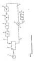
- an oscillator signal (1) of frequency ft is divided via a signal divider (2) into a measurement signal branch (3) and a reference signal branch (4).
- the N switchable phase shifters, here for example three in number (5), (6) and (7), and the test object (8) are arranged in a chain in the measuring branch.
- the mixer must be operated quasilinear in a known manner, which means that the mixer either works like an ideal multiplier and / or the signal of the reference branches must be large compared to the signal of the measuring branch.
- Ko also contains the complex conversion factor of the mixer.
- the object of this invention is to form the weighted sum analogously in a suitable manner quickly and accurately.
- the phase switches are set in such a way that the magnitude of their transfer function is as equal as possible in both positions, ie
- ⁇ 1, i 1 ... N, applies.
- Suitable phase switching values are also selected, for example in which any combination of the signs of the exponents can be chosen; the following examples use the positive values.
- the 180 ° switch fulfills important functions in that it eliminates the mixer offset voltage and increases the efficiency of the single sideband shifter.
- this phase switch could also be replaced by an amplitude modulator, which assumes the states 'on' and 'off' in the same way as the phase switch the states 0 ° and 180 °, so that the number of stages of the single sideband shifter would again be identical to the number of phase shifters .
- each active phase is denoted by ⁇ , the time interval between two successive active phases is r, where:
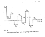
- Figure 2 shows a voltage curve as it can occur at the mixer output in the above arrangement; the voltages of the plateaus agree with the voltages U 1 , ..., U 8 , whereby, however, a suitable sequence must be observed, which is described here in Art to choose.
- Eq. (17) is used in conjunction with Eq. (15) clearly shows that the valid weighting factor p i changes with each step by the factor e -j45 ° or generally e -i36 ° / 2 . That is, the switching signals are arranged in time so that their start times applies, where to is any start time.
- this choice of the sign of the exponents in Eq. (12) also applies to others that under the p; each multiple of 360/2 N occurs exactly once.
- the temporal arrangement of the switching states shown and the bandpass filtering mean that the signal U a is weighted in the same way as the sum voltage U l according to equation (8).
- the sinusoidal output signal U l of the bandpass is an increasingly good measure of the complex transfer function of the high-frequency branch (3), namely in terms of amount and phase.
- the sequence of the phase switching states must be inverted in time.
- phase shifters can be fitted in the reference branch, it being important to note that in this case the weighting factors according to are to be chosen.
- the 180 switch can be replaced by an amplitude modulator in the high-frequency branch, just as individual phase switches can be put back in the reference branch.
Landscapes
- Engineering & Computer Science (AREA)
- Power Engineering (AREA)
- Networks Using Active Elements (AREA)
- Digital Transmission Methods That Use Modulated Carrier Waves (AREA)
- Amplitude Modulation (AREA)
Applications Claiming Priority (2)
| Application Number | Priority Date | Filing Date | Title |
|---|---|---|---|
| DE3821040A DE3821040C2 (de) | 1988-06-22 | 1988-06-22 | Mehrstufiger Einseitenbandversetzer |
| DE3821040 | 1988-06-23 |
Publications (2)
| Publication Number | Publication Date |
|---|---|
| EP0347833A2 true EP0347833A2 (fr) | 1989-12-27 |
| EP0347833A3 EP0347833A3 (fr) | 1990-07-11 |
Family
ID=6356997
Family Applications (1)
| Application Number | Title | Priority Date | Filing Date |
|---|---|---|---|
| EP89111182A Withdrawn EP0347833A3 (fr) | 1988-06-22 | 1989-06-20 | Changeur de fréquence à bande latérale unique à plusieurs étages |
Country Status (3)
| Country | Link |
|---|---|
| US (1) | US5142220A (fr) |
| EP (1) | EP0347833A3 (fr) |
| DE (1) | DE3821040C2 (fr) |
Family Cites Families (6)
| Publication number | Priority date | Publication date | Assignee | Title |
|---|---|---|---|---|
| US3290624A (en) * | 1964-02-10 | 1966-12-06 | Microwave Ass | Phase shifter in iterative circuits using semiconductors |
| GB1343033A (en) * | 1970-02-27 | 1974-01-10 | Emi Ltd | Frequency shift simulator |
| US3792378A (en) * | 1971-09-08 | 1974-02-12 | Us Navy | Digitally controlled rf sweep generator |
| DE3425961A1 (de) * | 1983-09-21 | 1985-04-04 | Bergwerksverband Gmbh, 4300 Essen | Verfahren und anordnung zur ermittlung und bestimmung des amplitudenverhaeltnisses und der phasendifferenz von signalen gleicher frequenz |
| US4709170A (en) * | 1984-08-20 | 1987-11-24 | National Semiconductor Corp. | Subnanosecond programmable phase shifter for a high frequency digital PLL |
| US4626796A (en) * | 1985-03-01 | 1986-12-02 | General Electric Company | Digital apparatus and method for programmably phase shifting an audio tone |
-
1988
- 1988-06-22 DE DE3821040A patent/DE3821040C2/de not_active Expired - Fee Related
-
1989
- 1989-06-20 EP EP89111182A patent/EP0347833A3/fr not_active Withdrawn
- 1989-06-22 US US07/369,809 patent/US5142220A/en not_active Expired - Fee Related
Also Published As
| Publication number | Publication date |
|---|---|
| EP0347833A3 (fr) | 1990-07-11 |
| DE3821040A1 (de) | 1989-12-28 |
| US5142220A (en) | 1992-08-25 |
| DE3821040C2 (de) | 1996-11-28 |
Similar Documents
| Publication | Publication Date | Title |
|---|---|---|
| DE2219085B2 (de) | Frequenzanalysator | |
| DE2513948C3 (de) | Stufig einstellbarer Frequenzgenerator mit einer phasengerasteten Regelschleife | |
| DE2603730A1 (de) | Anordnung und verfahren zur frequenzumschaltung insbesondere zur verwendung fuer die frequenzmessung | |
| EP0080157A2 (fr) | Procédé et montage pour la démodulation de signaux modulés en fréquence à partir de valeurs échantillonnées | |
| DE3425961C2 (fr) | ||
| DE4207045C2 (de) | Digitales Frequenzerzeugungsgerät | |
| DE2627586A1 (de) | Verfahren und schaltungsanordnung zur multiplikation von elektrischen signalen | |
| DE69330597T2 (de) | Mehrstufige frequenzmodulierte Schaltung | |
| EP0908735B1 (fr) | Procédé pour déterminer la fréquence d'un signal | |
| EP0347833A2 (fr) | Changeur de fréquence à bande latérale unique à plusieurs étages | |
| DE2310242A1 (de) | Anordnung zur gleichen verstaerkung von wenigstens zwei hochfrequenzspannungen | |
| EP0047477A1 (fr) | Radar Doppler à impulsion du type à élimination d'échos fixes utilisant un circuit à filtres récursifs | |
| DE2725099A1 (de) | Bodenstation fuer ein navigationssystem mit einer antenne fuer elektronische strahlschwenkung | |
| EP0015424A1 (fr) | Circuit pour produire successivement les valeurs de fonction de plusieurs oscillations dont les fréquences de répétition correspondent à N fois la valeur d'une fréquence fondamentale | |
| DE838788C (de) | Anordnung zur Erzeugung und Messung von Frequenzen | |
| DE1297157C2 (de) | Verfahren und Anordnung zur zentralen Erzeugung von Traegerfrequenzen eines TF-Systems | |
| DE1766797A1 (de) | Elektronische Anordnung mit mehreren Signalein- und -ausgaengen | |
| DE2753398C2 (de) | Verfahren zur digitalen Frequenzteilung | |
| DE963355C (de) | Verfahren und Schaltungsanordnung zur Messung des Phasenwinkels zwischen zwei gleichfrequenten elektrischen Wechselspannungen | |
| EP0260545B1 (fr) | Filtre actif | |
| DE2653475A1 (de) | Verfahren und schaltungsanordnung zu dessen durchfuehrung zur interpolation einer phasengerasteten frequenz | |
| DE2504763C3 (de) | Gyromagnetisches Resonanzspektrometer | |
| DE2855458C2 (de) | Rasteroszillator | |
| DE2603382B1 (de) | UEberlagerungsempfaenger mit phasenstarrer mehrmaliger Umsetzung eines Signals | |
| DE2660001C2 (de) | Vorrichtung zur Frequenzmessung |
Legal Events
| Date | Code | Title | Description |
|---|---|---|---|
| PUAI | Public reference made under article 153(3) epc to a published international application that has entered the european phase |
Free format text: ORIGINAL CODE: 0009012 |
|
| AK | Designated contracting states |
Kind code of ref document: A2 Designated state(s): AT CH DE ES FR GB IT LI NL SE |
|
| PUAL | Search report despatched |
Free format text: ORIGINAL CODE: 0009013 |
|
| AK | Designated contracting states |
Kind code of ref document: A3 Designated state(s): AT CH DE ES FR GB IT LI NL SE |
|
| 17P | Request for examination filed |
Effective date: 19910102 |
|
| 17Q | First examination report despatched |
Effective date: 19931105 |
|
| STAA | Information on the status of an ep patent application or granted ep patent |
Free format text: STATUS: THE APPLICATION HAS BEEN WITHDRAWN |
|
| 18W | Application withdrawn |
Withdrawal date: 19940421 |