EP0347790B1 - Flüssigkristallanzeigeeinheit und Methode zur Anzeige eines Bildes mit einer derartigen Einheit - Google Patents
Flüssigkristallanzeigeeinheit und Methode zur Anzeige eines Bildes mit einer derartigen Einheit Download PDFInfo
- Publication number
- EP0347790B1 EP0347790B1 EP89111071A EP89111071A EP0347790B1 EP 0347790 B1 EP0347790 B1 EP 0347790B1 EP 89111071 A EP89111071 A EP 89111071A EP 89111071 A EP89111071 A EP 89111071A EP 0347790 B1 EP0347790 B1 EP 0347790B1
- Authority
- EP
- European Patent Office
- Prior art keywords
- panel
- blue
- color
- liquid crystal
- image
- Prior art date
- Legal status (The legal status is an assumption and is not a legal conclusion. Google has not performed a legal analysis and makes no representation as to the accuracy of the status listed.)
- Expired - Lifetime
Links
- 238000000034 method Methods 0.000 title claims description 35
- 239000004973 liquid crystal related substance Substances 0.000 title claims description 33
- 239000000654 additive Substances 0.000 claims description 30
- 230000000996 additive effect Effects 0.000 claims description 30
- 239000003086 colorant Substances 0.000 claims description 21
- 230000005855 radiation Effects 0.000 claims description 11
- 239000000463 material Substances 0.000 claims description 10
- 230000005540 biological transmission Effects 0.000 claims description 7
- 239000011159 matrix material Substances 0.000 claims description 7
- 230000004044 response Effects 0.000 claims description 7
- 239000011521 glass Substances 0.000 claims description 6
- 230000000903 blocking effect Effects 0.000 claims 1
- 238000013459 approach Methods 0.000 description 11
- 230000002123 temporal effect Effects 0.000 description 10
- 230000000694 effects Effects 0.000 description 9
- 239000004020 conductor Substances 0.000 description 7
- 230000008901 benefit Effects 0.000 description 5
- 230000015572 biosynthetic process Effects 0.000 description 5
- 230000003595 spectral effect Effects 0.000 description 5
- 238000010586 diagram Methods 0.000 description 4
- 230000010354 integration Effects 0.000 description 4
- 239000002184 metal Substances 0.000 description 4
- 230000003287 optical effect Effects 0.000 description 4
- 238000001228 spectrum Methods 0.000 description 4
- 238000003786 synthesis reaction Methods 0.000 description 4
- 230000000007 visual effect Effects 0.000 description 4
- 238000003384 imaging method Methods 0.000 description 3
- 230000035945 sensitivity Effects 0.000 description 3
- 238000011161 development Methods 0.000 description 2
- 230000003292 diminished effect Effects 0.000 description 2
- 230000004927 fusion Effects 0.000 description 2
- 239000012212 insulator Substances 0.000 description 2
- 239000000203 mixture Substances 0.000 description 2
- 238000009877 rendering Methods 0.000 description 2
- 238000012163 sequencing technique Methods 0.000 description 2
- 239000010409 thin film Substances 0.000 description 2
- 241000385223 Villosa iris Species 0.000 description 1
- 230000004913 activation Effects 0.000 description 1
- 239000011149 active material Substances 0.000 description 1
- 230000002950 deficient Effects 0.000 description 1
- 230000001419 dependent effect Effects 0.000 description 1
- 239000000975 dye Substances 0.000 description 1
- 238000002474 experimental method Methods 0.000 description 1
- 230000036039 immunity Effects 0.000 description 1
- 230000007246 mechanism Effects 0.000 description 1
- 238000003672 processing method Methods 0.000 description 1
- 230000006798 recombination Effects 0.000 description 1
- 238000005215 recombination Methods 0.000 description 1
- 238000011160 research Methods 0.000 description 1
- 230000032554 response to blue light Effects 0.000 description 1
- 238000005406 washing Methods 0.000 description 1
Images


Classifications
-
- G—PHYSICS
- G02—OPTICS
- G02F—OPTICAL DEVICES OR ARRANGEMENTS FOR THE CONTROL OF LIGHT BY MODIFICATION OF THE OPTICAL PROPERTIES OF THE MEDIA OF THE ELEMENTS INVOLVED THEREIN; NON-LINEAR OPTICS; FREQUENCY-CHANGING OF LIGHT; OPTICAL LOGIC ELEMENTS; OPTICAL ANALOGUE/DIGITAL CONVERTERS
- G02F1/00—Devices or arrangements for the control of the intensity, colour, phase, polarisation or direction of light arriving from an independent light source, e.g. switching, gating or modulating; Non-linear optics
- G02F1/01—Devices or arrangements for the control of the intensity, colour, phase, polarisation or direction of light arriving from an independent light source, e.g. switching, gating or modulating; Non-linear optics for the control of the intensity, phase, polarisation or colour
- G02F1/13—Devices or arrangements for the control of the intensity, colour, phase, polarisation or direction of light arriving from an independent light source, e.g. switching, gating or modulating; Non-linear optics for the control of the intensity, phase, polarisation or colour based on liquid crystals, e.g. single liquid crystal display cells
- G02F1/133—Constructional arrangements; Operation of liquid crystal cells; Circuit arrangements
- G02F1/1333—Constructional arrangements; Manufacturing methods
- G02F1/1347—Arrangement of liquid crystal layers or cells in which the final condition of one light beam is achieved by the addition of the effects of two or more layers or cells
- G02F1/13475—Arrangement of liquid crystal layers or cells in which the final condition of one light beam is achieved by the addition of the effects of two or more layers or cells in which at least one liquid crystal cell or layer is doped with a pleochroic dye, e.g. GH-LC cell
Definitions
- the present invention relates to a liquid crystal color display unit and to a method for displaying an image with such unit.
- Liquid crystal mosaic display technology is being developed as a possible successor to color cathode ray tubes (CRTs) in many display applications, including those applications in the avionics field.
- This technology offers important advantages such as higher reliability along with reduced power, size and weight.
- capability of this technology for the rendering of an image falls short of the image capability achievable using CRT technology.
- This invention addresses three specific problem areas still remaining in liquid crystal mosaic displays: color definition; image resolution; and display brightness.
- color definition the liquid crystal mosaic display color rendition suffers from effects similar to those observed on a misaligned CRT display tube. The primary hues, the red, green and blue colors, do not blend properly.
- a white line for example, appears to have multicolored fringes, symptomatic of deficient color synthesis.
- Part of the problem can be attributed to the symbol generator which controls the formation of graphics on the flat panel.
- part of the problem can also be attributed to the display itself, a contribution addressed by this invention.
- Fig. 1A the low degree of spatial sensitivity that the human visual system has for blue light as compared to the other primary colors is illustrated.
- the eye's peak response to blue light occurs at about one half the frequency of peak response for the red radiation and half again the frequency for green radiation. This result indicates that blue radiation contributes only a minor amount to image shape and spatial detail.
- blue pixels on the display surface of the panel tend to degrade the overall resolution capability of color mosaic displays, a feature addressed by the present invention.
- the backlight technology includes the lamp and the electronics controlling the backlight lamp.
- the chief figure of merit for achieving a given level of brightness is how much power is needed to achieve that brightness level. Research is being aggressively pursued to make backlight technology more efficient.
- the present invention addresses the brightness problem from a different perspective.
- the pixel arrangement on the surface of the flat panel display can account for a considerable portion of the problem.
- Blue pixels contribute little to the total perceived luminance of the panel display.
- the photopic response of the eye accounts for this phenomenon.
- Figure 1B illustrates that red and green radiation provide a larger contribution to perceived brightness than blue radiation. Blue radiation can typically provide only about a ten percent contribution to the overall brightness of the panel.
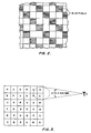
- FIG. 2 the effect of having blue pixels occupying space in the pixel arrangement is shown. Wherever a blue pixel is present, the effect on the pattern of pixels is to occlude the perceivable luminance passing through the display surface. No appreciable contribution to luminance capability is available at the sites of the blue pixels. As a result, these blue pixel regions of Figure 2 can be considered as black regions. These regions occupy thirty percent of useful area in a typical Red/Green/Blue (RGB) pixel mosaic arrangement.
- RGB Red/Green/Blue
- liquid crystal mosaic displays In order to compete successfully with the cathode ray tube technology in a multiplicity of applications, the liquid crystal mosaic displays must evolve to the point where they efficiently achieve enough brightness to prevent bright sunshine from washing out displayed information. Additionally, they must also exhibit higher resolution and improved color mixture attributes for higher quality imagery to be displayed. Achieving these goals has proven difficult in the past.
- Additive techniques use spatial proximity, temporal superposition or spatial superposition techniques to mix primary hues into different colors.
- Additive spatial proximity methods are the most common approach used in liquid crystal flat panel technology.
- Figure 3 illustrates the basic technique of spatial proximity. Small dots (pixels) of primary colors, typically red, green and blue, are evenly dispersed across the surface of the flat panel display. If the dots (pixels) are small enough and close enough, then the eye fuses or integrates the contribution of each color dot together with its neighbors.
- the additive method can achieve enhanced resolution by making the pixels smaller and more densely packed.
- the differently colored pixels can be arranged into different patterns, in hopes of striking a better fit with the characteristics of the human visual system.
- Full color imagery is therefore perceived.
- Excellent resolution can result because each pixel is capable of full color control and full luminance control.
- Color definition is faulty in the case of computer generated imagery (unless signal processing methods are used) resulting in color fringing and rainbows effects.
- As the pixels are made smaller color integration is improved but light output is worsened because a greater percentage of the primary display area gets consumed by address lines and interconnecting conductors.
- blue contributes very little to perceived brightness yet consumes typically one quarter to one third the active display area as indicated previously. Blue also detracts from resolution capability, limiting edge definition and image sharpness.
- the three principal problems with this approach then are: 1) poor color integration and 2) wasted luminance and 3) wasted resolution.
- the primary hues are rapidly sequenced before the eye.
- Figure 4 shows one possible sequence.
- the red portion of the image is flashed on the flat panel display, then the green portion of the image is flashed on the flat panel display and, a short time later, the blue portion of the image is flashed on the flat panel display.
- Successful color synthesis using this temporal additive technique depends on the limited temporal frequency response of human vision. If the sequencing occurs rapidly enough, the eye cannot discern the separate primary hues, but, instead, perceives their overall integrated image.
- Temporal superposition suffers from smearing effects, jitter and image instability as the observer shifts his viewing position rapidly or vibration induces similar motion.
- todays liquid crystal materials exhibit such slow optical response times, rapid temporal sequencing using them is virtually impossible.
- additive spatial superposition methods separate images, each comprised of only one primary hue, are optically fused into one full color image.
- three images corresponding to red, green and blue hues, are used.
- These separate images are formed from three separate image sources.
- the output images of these three sources are then fused by optics into one full color image to be viewed by the observer (cf. Figure 5).
- Excellent resolution is typical of this approach because each pixel is capable of full color and full luminance control.
- Brightness can also be high since three image forming sources are operated in parallel.
- Additive spatial superposition techniques suffer from complexity problems and performance difficulties. These systems also tend to be prohibitively large for many applications, especially those of the aerospace market. Cost generally rises due to the fact that three separate imaging devices are needed. Then additional hardware must be used to combine the three images. Frequently, this hardware must be extremely precise and rigid to maintain color purity.
- the object of the present invention to provide a liquid crystal color display unit and a method of displaying a color image on such a display unit that provides increased display brightness, increased image resolution and better color reproduction.
- Independent claim 7 is directed to a method for solving the indicated object.
- a liquid crystal display system in which a first panel has liquid crystal pixel elements that control the transmission of red and green image components and a second panel, aligned with the first panel for which liquid crystal pixel elements control the transmission blue image components therethrough.
- the first panel controls the red and green color components by additive spatial proximity techniques.
- the second panel controls the blue image component by subtractive techniques. Because of the reduced sensitivity of the eye to blue color components, the pixel array of the second panel can have diminished resolution and can have a diminished refresh rate compared to the first panel.
- Figure 1A illustrates the eye's lower spatial frequency for blue as compared to other primary colors.
- Figure 1B illustrates the reduced sensitivity to blue radiation as compared to radiation of the other primary colors.
- Figure 2 illustrates the regions (blue pixels) that do not contribute to the mosaic display luminance.
- Figure 3 illustrates how the eye integrates neighboring pixels to provide a full color spectrum from primary hues.
- Figure 4A and Figure 4B illustrate temporal integration of a sequence of primary color images to provide a complete image.
- Figure 5 is a block diagram illustrating the development of an image using spatial superposition of image portions.
- Figure 6 illustrates a controllable filter for creating a color image by removing selected portion of broad band optical transmission passing therethrough.
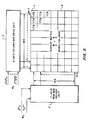
- Figure 7 is a schematic diagram of a first panel of an additive/subtractive display panel of the present invention.
- Figure 8A illustrates the passband characteristics of a magenta filter
- Figure 8B shows the passband characteristics of a cyan filter
- 8C illustrates the passband characteristics of dichroic filter for transmitting blue light.
- Figure 9 is a schematic diagram of a second panel of the additive/subtractive display of the present invention.
- Figure 10 is a cross-sectional view of the additive/subtractive display system according to the present invention.
- Figure 11 is a table illustrating the colors available with the additive/subtractive display panel of Fig. 10.
- Figure 12 is a CIE diagram illustrating the colors that can be achieved using the additive subtractive display system of the present invention.
- the liquid crystal display has an MxN matrix of pixels, each pixel being addressed by one of M column conductors and one of N row conductors.
- the M column conductors are selected by x-axis column bus drive unit 2 in response to groups of address signals, Wx, and the N row conductors are selected by y-row bus drive unit 3 in response to groups of address signals, Wy.
- Wx groups of address signals
- y-row bus drive unit 3 in response to groups of address signals
- the intersection of activated column conductors and an activated row conductor activates the associated pixels along the row. Either active matrix methods or multiplexing methods can be used to activate the pixels, techniques known in the related art.
- active devices such as thin film transistors or metal insulator metal diodes are used as switching or non-linear devices to control the storage of charge across each pixel.
- no active device is present.
- the relationships of voltage signals on row bus lines with respect to voltages present on column bus lines controls charge storage across each pixel which in turn controls the state of the pixel (liquid crystal) optically active material. This method depends on the sharp electro-optical threshold of the liquid crystal material itself rather than on the threshold behavior of intervening electronic devices used in active matrices.
- FIG. 7 the color pixel arrangement of the top layer of the additive subtractive display is illustrated. Pixels of one complimentary primary hue, (magenta filter) pixel 4, for example, are distributed in a checkerboard pattern with pixels of another complimentary primary hue (cyan filter) pixel 5.
- the checkerboard pattern is used by way of example and is not meant to be limiting.
- the optical passband characteristics of the magenta and cyan filters are shown in Fig. 8A and 8B. No blue primary hue pixels are present in the pixel pattern of the top surface. The use of only magenta and cyan filter pixels leads to the resolution and brightness advantages described earlier in the disclosure.
- the second panel 6 of the additive/subtractive display is shown.
- the matrix is shown with half the number (M/2 x N/2) of rows and columns used in the first panel 1.
- This degraded resoluticn is possible because of the lower spatial resolution capability human vision has for blue light modulation as compared to red and green light modulation.
- the drive units and address waveforms used for second panel 6 can be identical to those used for the first panel 1.
- the refresh rate of images displayed on the second panel 6 can be lowered relative to the refresh rate of the first panel 1 because human vision is less sensitive to blue light in terms of temporal resolution as well as spatial resolution.
- red/green images When red/green images are displayed on a display device whose images decay with time, the red/green images need to be refreshed periodically at a typical frequency of 60Hz.
- This critical fusion frequency allows the eye to integrate the flashing images into a steady scene absent of flicker or image decay. Blue light images can be seen without flicker at much lower refresh frequencies, 10Hz for example. This phenomenon can be used to have the overall effect of lowering the drive requirements for the blue color portion of the system.
- each pixel 7 controls the passage of blue light through the display.
- Each pixel can block blue light from passing through or, alternatively, can be energized so blue light can pass through unimpeded.
- a guest host dichroic liquid crystal material (Merck ZLI2010 for example) is used.
- the passband characteristics of this liquid crystal material are shown in Fig. 8c.
- the passband spectral characteristic is variable and is a function of applied voltage. If voltage of one value is applied, then the passband is 9 as shown by Fig. 8c. No blue light is allowed to be transmitted.
- the additive/subtractive display unit 100 includes a glass plate 14 and a glass plate 13 which enclose a region 16 containing dichroic material combined with a liquid crystal material.
- Pixel control devices 10 in region 16 and pixel control devices 11 in region 12 are also shown.
- These pixel control devices 10 and 11 can be active matrix control devices (thin film transistors or metal/insulator/metal diodes for example) or, alternatively, can represent the intersection points of the row/column electrodes of multiplexed display technology described above.
- the blue control devices 10 are shown with twice the spacing and, therefore, half the resolution of the red/green control devices 11. This reduced element spacing reflects the physical differences of human vision resolution for resolving colors described previously.
- the resolution of the second panel 6 can be identical to that of the first panel 1. This configuration has the effect of adding a higher degree of fault tolerance capability in addition to increased blue light resolution capability.
- Several blue panel control devices and their associated blue pixels can be activated simultaneously in this configuration to cover the same area as a lower resolution blue control pixel.
- the blue panel control devices 10 provide control over each pixel, enabling the additive/subtractive display to control the passage of blue light over the area of each cell or pixel 7 of Fig. 9 in the matrix of the second panel 6. Each pixel can either permit white light or yellow light to pass through the second panel 6 to the first panel 1.
- the red/green control devices 11 control the passage of light through the top layer 1. The red/green control devices determine whether any light is free to pass through the red-blue (magenta) 4 and green-blue (cyan) 5 filters located on the color filter surface of the top panel 1. Consequently, this layer not only controls hue but, significantly, controls brightness. Each pixel can be controlled to render gray shades as well as hue. This capability builds on the advantageous methods for rendering gray shades established by additive technology and avoids the distinctly complex luminance/chrominance interrelationships manifest in subtractive technology, alone.
- a black pixel 12 is desired, then the condition of the second panel 6 is inconsequential because any light passing through this panel will be blocked by the off condition of the magenta and cyan pixels in the first panel 1.
- lf a white region 13 is desired, then one half of the pixels of the second panel 6 must be in the pass "yellow plus blue" (white) state and the magenta 4 and cyan 5 pixels in first panel 1 must be fully ON.
- the panel in actuality produces only discrete magenta and cyan pixels in this state, the eye fuses them into white because of the close proximity of these hues.
- the pixels must be small enough and close enough to fall within the integration zone of the eye.
- the second panel 6 In order to produce a red region 14, the second panel 6 must be placed in the yellow or minus blue state 9 shown in Fig. 8.
- the magenta pixels 4 in the first panel 1 must be ON and the cyan pixels 5 in the desired region must be placed in the OFF state.
- a CIE color chart illustrating the range of colors which can be produced by gray level control of all pixels. If the blue control pixels 7 of the second panel 6 are varied from the pass blue state 8 plus 9 (all wavelengths are passed yielding white) to the block blue state 9, then each magenta pixel 4 moves from the magenta state to red along line 15 and each cyan pixel 5 moves from cyan to green along line 16 shown in Fig. 12. If blue is blocked entirely by pixels on layer 6, and if the cyan pixels 5 are ON and the magenta pixels are varied along a continuum from OFF to ON, then colors along line segment 17 will be produced, ending in yellow when the resultant green and red pixels are finally integrated by the eye.
- the present invention differs from prior art by tailoring the panel in better accord with the human visual system. Specifically, the invention addresses the fact that human vision relies almost exclusively on non-blue light, the red colors and the green colors, for spatial and intensity information. Further, the invention takes into account the fact that the eye uses blue light energy almost exclusively for chromatic information alone. Because blue light contributes very little to spatial detail and brightness, the invention removes blue light control from the principal display surface and dedicates this surface to the brighter and more resolvable red and green pixels. To achieve a wide range of colors, blue light control is placed behind the principal imaging layer, using techniques developed recently for the subtractive superpositional approach. Together, these two image planes add and subtract light to synthesize higher resolution, higher brightness images with a broad range of colors. The invention combines the simplicity and superior luminance control of one approach (additive juxtaposition) with the resolution enhancement of the second approach (superpositional subtractive).
- the display system of the present invention produces up to one third more luminance and resolution capability than predominant methods without incurring the volume and complexity cost of the other methods.
- Blue pixel control useful for color synthesis, but wasteful for brightness and image sharpness, is relegated to a secondary surface. This control leaves the primary display surface free to display the highly useful red and green pixels. These two display surfaces are sandwiched together into one compact flat panel display. Because imagery is not rapidly sequenced as a function of primary hue, the invention does not suffer from the temporal anomalies of temporal superposition approaches. Because it does not require recombination optics, it has a size advantage over spatial superposition methods. Finally, because it is primarily an additive display and uses only two imaging layers with blue on the secondary layer, it delivers more manageable luminance and color control, less complexity and parallax stability than the subtractive approach.
Landscapes
- Physics & Mathematics (AREA)
- Nonlinear Science (AREA)
- Mathematical Physics (AREA)
- Chemical & Material Sciences (AREA)
- Crystallography & Structural Chemistry (AREA)
- General Physics & Mathematics (AREA)
- Optics & Photonics (AREA)
- Devices For Indicating Variable Information By Combining Individual Elements (AREA)
- Liquid Crystal (AREA)
- Liquid Crystal Display Device Control (AREA)
- Video Image Reproduction Devices For Color Tv Systems (AREA)
Claims (7)
- Flüssigkristall-Farbanzeigeeinheit zur Verwendung mit einer Breitband-Lichtquelle, welche Anzeigeeinheit eine erste Flüssigkristallplatte (1) umfaßt, die auf einer zweiten Flüssigkristallplatte (6) gestapelt ist, wobei die erste Platte (1) die Übertragung roter und grüner Lichtkomponenten steuert und umfaßt- ein Flüssigkristallmaterial (12) das zwischen zwei zueinander parallelen Glasplatten (13,15) eingegrenzt ist;- kombinierte Farbelemente, von denen jedes ein Mosaik von Rot/Blau-Farbfiltern und Grün/Blau-Farbfiltern umfaßt, wobei die kombinierten Farbelemente auf der äußeren Glasplatte (13) angeordnet sind;- mehrere erste Steuerelemente (11), welche definierena) mehrere erste steuerbare Pixeleinheiten (4) für die Steuerung der Lichtübertragung durch das Rot/Blau-Farbfilter undb) mehrere zweite steuerbare Pixeleinheiten (5) für die Steuerung der Lichtübertragung durch das Grün/Blau-Farbfilter;wobei die zweite Platte (6) die Übertragung der blauen Lichtkomponente der Breitband-Lichtquelle steuert, die die erste Platte durch die zweite Platte beleuchtet, welche zweite Platte umfaßt- ein dichroitisches Material;- ein Flüssigkristallmaterial (16), das zwischen zwei zueinander parallelen Glasplatten (13,14) eingegrenzt ist;- mehrere zweite Steuerelemente (10), die mehrere dritte steuerbare Pixeleinheiten (7) definieren, von denen jedes auf ein kombiniertes Farbelement auf der ersten Platte ausgerichtet ist; und
wobei die zweite Platte steuerbar die blaue Komponente aus dem Beleuchtungslicht subtrahiert, so daß die Rot/Blau- und Grün/Blau-Farbfilter auf der ersten Platte steuerbar mit Licht beleuchtet werden, das die blaue Komponente enhält bzw. nicht enthält, wodurch eine Farbanzeige auf Grund der additiven Farbmischung im Auge des Beobachters erzeugt wird. - Anzeigeeinheit nach Anspruch 1, dadurch gekennzeichnet, daß die Bildauflösung durch die Pixeleinheiten (4,5) der ersten Platte (1) festgelegt ist.
- Anzeigeeinheit nach Anspruch 1, dadurch gekennzeichnet, daß die Helligkeitsparameter eines Bildes durch die Pixeleinheiten (4,5) der ersten Platte (1) gesteuert werden.
- Anzeigeeinheit nach Anspruch 3, dadurch gekennzeichnet, daß mehrere Pixeleinheiten (4,5,7) unter Verwendung der Matrix-Adressiertechnik gesteuert werden.
- Anzeigeeinheit nach einem der Ansprüche 1 bis 4, dadurch gekennzeichnet, daß die Pixeleinheiten (7) der zweiten Platte (6) wenigstens so groß wie die Pixeleinheiten (4,5) der ersten Platte sind, wobei eine Pixeleinheit (7) der zweiten Platte Strahlung von der Breitband-Lichtquelle zu mehreren Pixeleinheiten der ersten Platte überträgt.
- Anzeigeeinheit nach Anspruch 5, dadurch gekennzeichnet, daß Farben des Bildes erhalten werden durch die Kombination der durch mehrere benachbarte Pixeleinheiten (4,5) der ersten Platte (1) übertragenen Strahlung.
- Verfahren für die Darstellung eines Farbbildes auf einer Flüssigkristall-Anzeigeeinheit, gekennzeichnet durch die Schritte:
steuerbare Blockierung oder Übertragung von blauen Bildkomponenten in einer ersten Flüssigkristallplatte auf Grund des von einer Breitband-Lichtquelle zugeführten weißen Lichtes; und
Verwendung von solchem gefilterten oder nicht-gefiltertem Licht zur Beleuchtung eines Mosaiks von Rot/Blau- und Grün/Blau-Filterelementen auf einer zweiten Flüssigkristallplatte, um den Farbenbereich zu erzeugen, der für die Erzeugung des Farbbildes im Auge eines Beobachters durch additive Farbmischung erforderlich ist.
Applications Claiming Priority (2)
| Application Number | Priority Date | Filing Date | Title |
|---|---|---|---|
| US07/211,827 US4886343A (en) | 1988-06-20 | 1988-06-20 | Apparatus and method for additive/subtractive pixel arrangement in color mosaic displays |
| US211827 | 1988-06-20 |
Publications (3)
| Publication Number | Publication Date |
|---|---|
| EP0347790A2 EP0347790A2 (de) | 1989-12-27 |
| EP0347790A3 EP0347790A3 (en) | 1990-08-22 |
| EP0347790B1 true EP0347790B1 (de) | 1994-02-16 |
Family
ID=22788505
Family Applications (1)
| Application Number | Title | Priority Date | Filing Date |
|---|---|---|---|
| EP89111071A Expired - Lifetime EP0347790B1 (de) | 1988-06-20 | 1989-06-19 | Flüssigkristallanzeigeeinheit und Methode zur Anzeige eines Bildes mit einer derartigen Einheit |
Country Status (6)
| Country | Link |
|---|---|
| US (1) | US4886343A (de) |
| EP (1) | EP0347790B1 (de) |
| JP (1) | JP2797199B2 (de) |
| CA (1) | CA1331408C (de) |
| DE (1) | DE68913084T2 (de) |
| ES (1) | ES2050188T3 (de) |
Families Citing this family (90)
| Publication number | Priority date | Publication date | Assignee | Title |
|---|---|---|---|---|
| US5032007A (en) * | 1988-04-07 | 1991-07-16 | Honeywell, Inc. | Apparatus and method for an electronically controlled color filter for use in information display applications |
| US5225875A (en) * | 1988-07-21 | 1993-07-06 | Proxima Corporation | High speed color display system and method of using same |
| US5276436A (en) * | 1988-07-21 | 1994-01-04 | Proxima Corporation | Television signal projection system and method of using same |
| US5153568A (en) * | 1988-07-21 | 1992-10-06 | Proxima Corporation | Liquid crystal display panel system and method of using same |
| US5300944A (en) * | 1988-07-21 | 1994-04-05 | Proxima Corporation | Video display system and method of using same |
| US5264835A (en) * | 1988-07-21 | 1993-11-23 | Proxima Corporation | Enhanced color display system and method of using same |
| USRE36654E (en) | 1989-03-28 | 2000-04-11 | In Focus Systems, Inc. | Stacked LCD color display |
| JPH03231288A (ja) * | 1990-01-30 | 1991-10-15 | Proxima Corp | 液晶表示パネル装置及びその使用法 |
| US5206749A (en) * | 1990-12-31 | 1993-04-27 | Kopin Corporation | Liquid crystal display having essentially single crystal transistors pixels and driving circuits |
| DE69125125T2 (de) * | 1990-12-27 | 1997-08-21 | Philips Electronics Nv | Farbbildanzeigevorrichtung und Schaltung zur Ansteuerung vom Lichtventil einer solcher Vorrichtung |
| US5743614A (en) * | 1990-12-31 | 1998-04-28 | Kopin Corporation | Housing assembly for a matrix display |
| US5444557A (en) * | 1990-12-31 | 1995-08-22 | Kopin Corporation | Single crystal silicon arrayed devices for projection displays |
| US5751261A (en) * | 1990-12-31 | 1998-05-12 | Kopin Corporation | Control system for display panels |
| US5661371A (en) * | 1990-12-31 | 1997-08-26 | Kopin Corporation | Color filter system for light emitting display panels |
| US6320568B1 (en) | 1990-12-31 | 2001-11-20 | Kopin Corporation | Control system for display panels |
| US5376979A (en) * | 1990-12-31 | 1994-12-27 | Kopin Corporation | Slide projector mountable light valve display |
| US5861929A (en) * | 1990-12-31 | 1999-01-19 | Kopin Corporation | Active matrix color display with multiple cells and connection through substrate |
| JP2829149B2 (ja) * | 1991-04-10 | 1998-11-25 | シャープ株式会社 | 液晶表示装置 |
| EP0516076B1 (de) * | 1991-05-27 | 1999-04-07 | Dainippon Ink And Chemicals, Inc. | Flüssigkristallvorrichtung |
| EP0543658B1 (de) * | 1991-11-21 | 1999-03-31 | Fujitsu Limited | Farbige Flüssigkristall-Anzeigevorrichtung |
| WO1993011452A1 (en) * | 1991-11-25 | 1993-06-10 | Magnascreen Corporation | Microprojection display system with fiber-optic illuminator, and method of display and illumination |
| DE4300246A1 (en) * | 1992-01-08 | 1993-07-15 | Terumo Corp | Depth scanner for displaying three=dimensional pictures without lenses - projects collimated light through object to be scanned and condenses light and filters to remove direct flow component |
| JP2672055B2 (ja) * | 1992-05-08 | 1997-11-05 | 信幸 山村 | 液晶表示素子とその製造方法及びこれを使用する表示装置 |
| US5289301A (en) * | 1992-06-12 | 1994-02-22 | Boit, Inc. | Liquid crystal color modulation displays with dyes of different orders and circuitry for providing modulated AC excitation voltage |
| JP3329887B2 (ja) * | 1992-06-17 | 2002-09-30 | ゼロックス・コーポレーション | 2光路液晶ライトバルブカラー表示装置 |
| US5315418A (en) * | 1992-06-17 | 1994-05-24 | Xerox Corporation | Two path liquid crystal light valve color display with light coupling lens array disposed along the red-green light path |
| US5414543A (en) * | 1992-08-24 | 1995-05-09 | Samsung Electronics Co., Ltd. | Method for manufacturing a multiple level liquid crystal display using alternating metal and metal oxide layers |
| JPH06202099A (ja) * | 1992-09-17 | 1994-07-22 | Fujitsu Ltd | 液晶表示パネル |
| US5724109A (en) * | 1992-09-17 | 1998-03-03 | Fujitsu Limited | Liquid crystal display panel with electrodes or a passivation layer intermediate two liquid crystal layers |
| US5781164A (en) * | 1992-11-04 | 1998-07-14 | Kopin Corporation | Matrix display systems |
| KR100230354B1 (ko) * | 1992-11-26 | 1999-11-15 | 윤종용 | 광산란형 액정 표시 장치의 제조 방법 |
| US5371618A (en) * | 1993-01-05 | 1994-12-06 | Brite View Technologies | Color liquid crystal display employing dual cells driven with an EXCLUSIVE OR relationship |
| US5309169A (en) * | 1993-02-01 | 1994-05-03 | Honeywell Inc. | Visor display with fiber optic faceplate correction |
| KR970000357B1 (ko) * | 1993-04-29 | 1997-01-08 | 삼성전자 주식회사 | 액정 표시소자와 그 제조방법 |
| US5563727A (en) * | 1994-06-30 | 1996-10-08 | Honeywell Inc. | High aperture AMLCD with nonparallel alignment of addressing lines to the pixel edges or with distributed analog processing at the pixel level |
| JP3071658B2 (ja) * | 1994-11-02 | 2000-07-31 | シャープ株式会社 | 液晶表示素子 |
| FR2737829B1 (fr) * | 1995-08-11 | 1997-09-12 | Sextant Avionique | Afficheur d'images video en couleur |
| US5801796A (en) * | 1996-05-10 | 1998-09-01 | International Business Machines Corporation | Stacked parallax-free liquid crystal display cell |
| US6046716A (en) * | 1996-12-19 | 2000-04-04 | Colorado Microdisplay, Inc. | Display system having electrode modulation to alter a state of an electro-optic layer |
| US6078303A (en) | 1996-12-19 | 2000-06-20 | Colorado Microdisplay, Inc. | Display system having electrode modulation to alter a state of an electro-optic layer |
| US5920298A (en) * | 1996-12-19 | 1999-07-06 | Colorado Microdisplay, Inc. | Display system having common electrode modulation |
| JP3974217B2 (ja) | 1997-04-02 | 2007-09-12 | シャープ株式会社 | 液晶表示パネルおよび液晶表示装置 |
| HUP9800510A3 (en) * | 1998-03-09 | 2000-07-28 | Kolta Peter | Method and device for detecting colour vision deficiencies based on critical fusion frequency spectral scanning |
| US5982464A (en) * | 1998-12-16 | 1999-11-09 | Technoloogy Resource International Corporation | Multi-twist color liquid crystal display |
| US7283142B2 (en) * | 2000-07-28 | 2007-10-16 | Clairvoyante, Inc. | Color display having horizontal sub-pixel arrangements and layouts |
| US6950115B2 (en) | 2001-05-09 | 2005-09-27 | Clairvoyante, Inc. | Color flat panel display sub-pixel arrangements and layouts |
| US8022969B2 (en) | 2001-05-09 | 2011-09-20 | Samsung Electronics Co., Ltd. | Rotatable display with sub-pixel rendering |
| EP1314149B1 (de) | 2000-07-28 | 2014-05-21 | Samsung Display Co., Ltd. | Anordnung von farbigen pixeln für vollfarben anzeigevorrichtungen mit vereinfachter adressierung |
| US7274383B1 (en) | 2000-07-28 | 2007-09-25 | Clairvoyante, Inc | Arrangement of color pixels for full color imaging devices with simplified addressing |
| US7123277B2 (en) * | 2001-05-09 | 2006-10-17 | Clairvoyante, Inc. | Conversion of a sub-pixel format data to another sub-pixel data format |
| US7221381B2 (en) | 2001-05-09 | 2007-05-22 | Clairvoyante, Inc | Methods and systems for sub-pixel rendering with gamma adjustment |
| US7184066B2 (en) | 2001-05-09 | 2007-02-27 | Clairvoyante, Inc | Methods and systems for sub-pixel rendering with adaptive filtering |
| JP4703029B2 (ja) * | 2001-05-14 | 2011-06-15 | 三菱電機株式会社 | 画像表示システム及び画像表示方法 |
| KR100444499B1 (ko) * | 2001-09-21 | 2004-08-16 | 엘지전자 주식회사 | 일렉트로 루미네센스 패널 및 그 구동방법 |
| AU2002353139A1 (en) | 2001-12-14 | 2003-06-30 | Clairvoyante Laboratories, Inc. | Improvements to color flat panel display sub-pixel arrangements and layouts with reduced visibility of a blue luminance well |
| US7755652B2 (en) | 2002-01-07 | 2010-07-13 | Samsung Electronics Co., Ltd. | Color flat panel display sub-pixel rendering and driver configuration for sub-pixel arrangements with split sub-pixels |
| US7417648B2 (en) | 2002-01-07 | 2008-08-26 | Samsung Electronics Co. Ltd., | Color flat panel display sub-pixel arrangements and layouts for sub-pixel rendering with split blue sub-pixels |
| US20040051724A1 (en) | 2002-09-13 | 2004-03-18 | Elliott Candice Hellen Brown | Four color arrangements of emitters for subpixel rendering |
| US7492379B2 (en) | 2002-01-07 | 2009-02-17 | Samsung Electronics Co., Ltd. | Color flat panel display sub-pixel arrangements and layouts for sub-pixel rendering with increased modulation transfer function response |
| JP2005517994A (ja) * | 2002-02-19 | 2005-06-16 | コーニンクレッカ フィリップス エレクトロニクス エヌ ヴィ | ディスプレイ・デバイス |
| US7046256B2 (en) | 2003-01-22 | 2006-05-16 | Clairvoyante, Inc | System and methods of subpixel rendering implemented on display panels |
| US20040196302A1 (en) | 2003-03-04 | 2004-10-07 | Im Moon Hwan | Systems and methods for temporal subpixel rendering of image data |
| US7167186B2 (en) | 2003-03-04 | 2007-01-23 | Clairvoyante, Inc | Systems and methods for motion adaptive filtering |
| US6917368B2 (en) * | 2003-03-04 | 2005-07-12 | Clairvoyante, Inc. | Sub-pixel rendering system and method for improved display viewing angles |
| JP4402358B2 (ja) * | 2003-03-05 | 2010-01-20 | キヤノン株式会社 | カラー画像表示パネルおよびその駆動方法 |
| US7352374B2 (en) | 2003-04-07 | 2008-04-01 | Clairvoyante, Inc | Image data set with embedded pre-subpixel rendered image |
| US7268748B2 (en) | 2003-05-20 | 2007-09-11 | Clairvoyante, Inc | Subpixel rendering for cathode ray tube devices |
| US7230584B2 (en) | 2003-05-20 | 2007-06-12 | Clairvoyante, Inc | Projector systems with reduced flicker |
| US20040246280A1 (en) | 2003-06-06 | 2004-12-09 | Credelle Thomas Lloyd | Image degradation correction in novel liquid crystal displays |
| US7218301B2 (en) | 2003-06-06 | 2007-05-15 | Clairvoyante, Inc | System and method of performing dot inversion with standard drivers and backplane on novel display panel layouts |
| US7209105B2 (en) | 2003-06-06 | 2007-04-24 | Clairvoyante, Inc | System and method for compensating for visual effects upon panels having fixed pattern noise with reduced quantization error |
| US8035599B2 (en) | 2003-06-06 | 2011-10-11 | Samsung Electronics Co., Ltd. | Display panel having crossover connections effecting dot inversion |
| US7187353B2 (en) | 2003-06-06 | 2007-03-06 | Clairvoyante, Inc | Dot inversion on novel display panel layouts with extra drivers |
| US7397455B2 (en) | 2003-06-06 | 2008-07-08 | Samsung Electronics Co., Ltd. | Liquid crystal display backplane layouts and addressing for non-standard subpixel arrangements |
| US7084923B2 (en) | 2003-10-28 | 2006-08-01 | Clairvoyante, Inc | Display system having improved multiple modes for displaying image data from multiple input source formats |
| US7525526B2 (en) | 2003-10-28 | 2009-04-28 | Samsung Electronics Co., Ltd. | System and method for performing image reconstruction and subpixel rendering to effect scaling for multi-mode display |
| US7248268B2 (en) | 2004-04-09 | 2007-07-24 | Clairvoyante, Inc | Subpixel rendering filters for high brightness subpixel layouts |
| US20050250821A1 (en) * | 2004-04-16 | 2005-11-10 | Vincent Sewalt | Quaternary ammonium compounds in the treatment of water and as antimicrobial wash |
| US7590299B2 (en) | 2004-06-10 | 2009-09-15 | Samsung Electronics Co., Ltd. | Increasing gamma accuracy in quantized systems |
| US7511716B2 (en) | 2005-04-29 | 2009-03-31 | Sony Corporation | High-resolution micro-lens 3D display with shared sub-pixel color signals |
| US8018476B2 (en) | 2006-08-28 | 2011-09-13 | Samsung Electronics Co., Ltd. | Subpixel layouts for high brightness displays and systems |
| US7876341B2 (en) | 2006-08-28 | 2011-01-25 | Samsung Electronics Co., Ltd. | Subpixel layouts for high brightness displays and systems |
| US8049685B2 (en) * | 2006-11-09 | 2011-11-01 | Global Oled Technology Llc | Passive matrix thin-film electro-luminescent display |
| CN101542377B (zh) | 2006-11-30 | 2014-08-06 | 皇家飞利浦电子股份有限公司 | 减色显示器 |
| US7643107B2 (en) * | 2007-05-01 | 2010-01-05 | Citizen Holdings Co., Ltd. | Liquid crystal display apparatus |
| US8827488B2 (en) | 2008-10-01 | 2014-09-09 | Universal Display Corporation | OLED display architecture |
| US20100225252A1 (en) * | 2008-10-01 | 2010-09-09 | Universal Display Corporation | Novel amoled display architecture |
| US9385167B2 (en) * | 2008-10-01 | 2016-07-05 | Universal Display Corporation | OLED display architecture |
| TWI415045B (zh) * | 2009-02-24 | 2013-11-11 | Ind Tech Res Inst | 反射式顯示器的畫素結構 |
| CN103325320B (zh) * | 2013-07-06 | 2015-06-10 | 长春希达电子技术有限公司 | 同色芯片斜线排列的led显示屏及像素复用的方法 |
Family Cites Families (14)
| Publication number | Priority date | Publication date | Assignee | Title |
|---|---|---|---|---|
| US3703329A (en) * | 1969-12-29 | 1972-11-21 | Rca Corp | Liquid crystal color display |
| JPS53101296A (en) * | 1977-02-16 | 1978-09-04 | Seiko Epson Corp | Display unit |
| JPS5961818A (ja) * | 1982-10-01 | 1984-04-09 | Seiko Epson Corp | 液晶表示装置 |
| JPS59219719A (ja) * | 1983-05-27 | 1984-12-11 | Seiko Instr & Electronics Ltd | カラ−液晶表示装置 |
| IL70115A (en) * | 1983-11-02 | 1987-02-27 | Stolov Michael | Substratum for large and/or high contrast liquid crystal display |
| JPS60186889A (ja) * | 1984-03-07 | 1985-09-24 | スタンレー電気株式会社 | 多層マトリクス型液晶表示装置 |
| JPH0680451B2 (ja) * | 1984-03-16 | 1994-10-12 | シチズン時計株式会社 | 多色表示装置 |
| US4772885A (en) * | 1984-11-22 | 1988-09-20 | Ricoh Company, Ltd. | Liquid crystal color display device |
| US4793691A (en) * | 1984-12-25 | 1988-12-27 | Ricoh Company, Ltd. | Liquid crystal color display device |
| JP2677790B2 (ja) * | 1985-03-01 | 1997-11-17 | マンチェスター アール アンド デイ リミテッド パートナーシップ | 液晶カラーデバイス |
| US4770500A (en) * | 1986-06-10 | 1988-09-13 | Kaiser Aerospace And Electronics Corporation | Method and apparatus for multi color display |
| US4799050A (en) * | 1986-10-23 | 1989-01-17 | Litton Systems Canada Limited | Full color liquid crystal display |
| FR2618008B1 (fr) * | 1987-07-07 | 1989-10-20 | Commissariat Energie Atomique | Ecran polychrome |
| US4811003A (en) * | 1987-10-23 | 1989-03-07 | Rockwell International Corporation | Alternating parallelogram display elements |
-
1988
- 1988-06-20 US US07/211,827 patent/US4886343A/en not_active Expired - Lifetime
-
1989
- 1989-06-19 ES ES89111071T patent/ES2050188T3/es not_active Expired - Lifetime
- 1989-06-19 CA CA000603226A patent/CA1331408C/en not_active Expired - Fee Related
- 1989-06-19 EP EP89111071A patent/EP0347790B1/de not_active Expired - Lifetime
- 1989-06-19 DE DE68913084T patent/DE68913084T2/de not_active Expired - Fee Related
- 1989-06-20 JP JP1155995A patent/JP2797199B2/ja not_active Expired - Fee Related
Also Published As
| Publication number | Publication date |
|---|---|
| EP0347790A3 (en) | 1990-08-22 |
| DE68913084T2 (de) | 1994-07-14 |
| US4886343A (en) | 1989-12-12 |
| JP2797199B2 (ja) | 1998-09-17 |
| DE68913084D1 (de) | 1994-03-24 |
| EP0347790A2 (de) | 1989-12-27 |
| JPH02110430A (ja) | 1990-04-23 |
| CA1331408C (en) | 1994-08-09 |
| ES2050188T3 (es) | 1994-05-16 |
Similar Documents
| Publication | Publication Date | Title |
|---|---|---|
| EP0347790B1 (de) | Flüssigkristallanzeigeeinheit und Methode zur Anzeige eines Bildes mit einer derartigen Einheit | |
| US5032007A (en) | Apparatus and method for an electronically controlled color filter for use in information display applications | |
| US5006840A (en) | Color liquid-crystal display apparatus with rectilinear arrangement | |
| US5528262A (en) | Method for line field-sequential color video display | |
| EP0752610B1 (de) | Räumlicher Lichtmodulator und gerichtete Anzeigevorrichtung | |
| EP0158366B1 (de) | Farb-Flüssigkristallanzeigevorrichtung | |
| JP2852040B2 (ja) | ディスプレイ装置及び方法 | |
| KR100604705B1 (ko) | 액티브 매트릭스 액정 표시 장치 | |
| EP1758088A2 (de) | Farbanzeigevorrichtung und -verfahren | |
| US9082349B2 (en) | Multi-primary display with active backlight | |
| US6184951B1 (en) | Liquid crystal display wherein each pixels of first layer is optically aligned with respective group of pixels of second layer | |
| JP3009929B2 (ja) | 反対色を用いるマルチカラー表示方法及び表示デバイス | |
| JP2005233982A (ja) | 表示装置、表示装置の駆動方法、表示情報形成装置、および表示情報伝送方式 | |
| KR100362957B1 (ko) | 디스플레이장치및디스플레이시스템 | |
| US5278681A (en) | Combined color and monochrome display | |
| JP2004117431A (ja) | カラー表示装置 | |
| US20080174849A1 (en) | Display apparatus | |
| JPH02118521A (ja) | 液晶表示装置 | |
| JP4498205B2 (ja) | 表示装置 | |
| US8687143B2 (en) | Multi-primary display with area active backlight | |
| WO2009040758A2 (en) | Spectrum-sequential display | |
| US5473340A (en) | Apparatus for displaying a multi-color pattern | |
| JPS60131522A (ja) | カラ−液晶表示装置 | |
| Post | Miniature color display for airborne helmet-mounted displays (HMDs) | |
| Allen | A 1" high resolution field sequential display for head mounted applications |
Legal Events
| Date | Code | Title | Description |
|---|---|---|---|
| PUAI | Public reference made under article 153(3) epc to a published international application that has entered the european phase |
Free format text: ORIGINAL CODE: 0009012 |
|
| AK | Designated contracting states |
Kind code of ref document: A2 Designated state(s): DE ES FR GB IT NL |
|
| PUAL | Search report despatched |
Free format text: ORIGINAL CODE: 0009013 |
|
| AK | Designated contracting states |
Kind code of ref document: A3 Designated state(s): DE ES FR GB IT NL |
|
| 17P | Request for examination filed |
Effective date: 19901213 |
|
| 17Q | First examination report despatched |
Effective date: 19920902 |
|
| GRAA | (expected) grant |
Free format text: ORIGINAL CODE: 0009210 |
|
| AK | Designated contracting states |
Kind code of ref document: B1 Designated state(s): DE ES FR GB IT NL |
|
| REF | Corresponds to: |
Ref document number: 68913084 Country of ref document: DE Date of ref document: 19940324 |
|
| ET | Fr: translation filed | ||
| ITF | It: translation for a ep patent filed | ||
| REG | Reference to a national code |
Ref country code: ES Ref legal event code: FG2A Ref document number: 2050188 Country of ref document: ES Kind code of ref document: T3 |
|
| PLBE | No opposition filed within time limit |
Free format text: ORIGINAL CODE: 0009261 |
|
| STAA | Information on the status of an ep patent application or granted ep patent |
Free format text: STATUS: NO OPPOSITION FILED WITHIN TIME LIMIT |
|
| 26N | No opposition filed | ||
| REG | Reference to a national code |
Ref country code: GB Ref legal event code: IF02 |
|
| PGFP | Annual fee paid to national office [announced via postgrant information from national office to epo] |
Ref country code: NL Payment date: 20030513 Year of fee payment: 15 |
|
| PGFP | Annual fee paid to national office [announced via postgrant information from national office to epo] |
Ref country code: ES Payment date: 20030620 Year of fee payment: 15 |
|
| PG25 | Lapsed in a contracting state [announced via postgrant information from national office to epo] |
Ref country code: ES Free format text: LAPSE BECAUSE OF NON-PAYMENT OF DUE FEES Effective date: 20040621 |
|
| PG25 | Lapsed in a contracting state [announced via postgrant information from national office to epo] |
Ref country code: NL Free format text: LAPSE BECAUSE OF NON-PAYMENT OF DUE FEES Effective date: 20050101 |
|
| NLV4 | Nl: lapsed or anulled due to non-payment of the annual fee |
Effective date: 20050101 |
|
| PGFP | Annual fee paid to national office [announced via postgrant information from national office to epo] |
Ref country code: GB Payment date: 20050506 Year of fee payment: 17 |
|
| PGFP | Annual fee paid to national office [announced via postgrant information from national office to epo] |
Ref country code: FR Payment date: 20050602 Year of fee payment: 17 |
|
| PG25 | Lapsed in a contracting state [announced via postgrant information from national office to epo] |
Ref country code: IT Free format text: LAPSE BECAUSE OF NON-PAYMENT OF DUE FEES;WARNING: LAPSES OF ITALIAN PATENTS WITH EFFECTIVE DATE BEFORE 2007 MAY HAVE OCCURRED AT ANY TIME BEFORE 2007. THE CORRECT EFFECTIVE DATE MAY BE DIFFERENT FROM THE ONE RECORDED. Effective date: 20050619 |
|
| PGFP | Annual fee paid to national office [announced via postgrant information from national office to epo] |
Ref country code: DE Payment date: 20050630 Year of fee payment: 17 |
|
| REG | Reference to a national code |
Ref country code: ES Ref legal event code: FD2A Effective date: 20040621 |
|
| PG25 | Lapsed in a contracting state [announced via postgrant information from national office to epo] |
Ref country code: GB Free format text: LAPSE BECAUSE OF NON-PAYMENT OF DUE FEES Effective date: 20060619 |
|
| PG25 | Lapsed in a contracting state [announced via postgrant information from national office to epo] |
Ref country code: DE Free format text: LAPSE BECAUSE OF NON-PAYMENT OF DUE FEES Effective date: 20070103 |
|
| GBPC | Gb: european patent ceased through non-payment of renewal fee |
Effective date: 20060619 |
|
| REG | Reference to a national code |
Ref country code: FR Ref legal event code: ST Effective date: 20070228 |
|
| PG25 | Lapsed in a contracting state [announced via postgrant information from national office to epo] |
Ref country code: FR Free format text: LAPSE BECAUSE OF NON-PAYMENT OF DUE FEES Effective date: 20060630 |
|
| P01 | Opt-out of the competence of the unified patent court (upc) registered |
Effective date: 20230525 |