EP0347752A2 - Verfahren zur Steuerung der Leimviskosität und Steuergerät für eine Leimmaschine - Google Patents
Verfahren zur Steuerung der Leimviskosität und Steuergerät für eine Leimmaschine Download PDFInfo
- Publication number
- EP0347752A2 EP0347752A2 EP89110873A EP89110873A EP0347752A2 EP 0347752 A2 EP0347752 A2 EP 0347752A2 EP 89110873 A EP89110873 A EP 89110873A EP 89110873 A EP89110873 A EP 89110873A EP 0347752 A2 EP0347752 A2 EP 0347752A2
- Authority
- EP
- European Patent Office
- Prior art keywords
- size
- viscosity
- temperature
- heat supply
- unit
- Prior art date
- Legal status (The legal status is an assumption and is not a legal conclusion. Google has not performed a legal analysis and makes no representation as to the accuracy of the status listed.)
- Granted
Links
Images


Classifications
-
- D—TEXTILES; PAPER
- D02—YARNS; MECHANICAL FINISHING OF YARNS OR ROPES; WARPING OR BEAMING
- D02H—WARPING, BEAMING OR LEASING
- D02H5/00—Beaming machines
- D02H5/02—Beaming machines combined with apparatus for sizing or other treatment of warps
-
- D—TEXTILES; PAPER
- D06—TREATMENT OF TEXTILES OR THE LIKE; LAUNDERING; FLEXIBLE MATERIALS NOT OTHERWISE PROVIDED FOR
- D06B—TREATING TEXTILE MATERIALS USING LIQUIDS, GASES OR VAPOURS
- D06B23/00—Component parts, details, or accessories of apparatus or machines, specially adapted for the treating of textile materials, not restricted to a particular kind of apparatus, provided for in groups D06B1/00 - D06B21/00
- D06B23/20—Arrangements of apparatus for treating processing-liquids, -gases or -vapours, e.g. purification, filtration or distillation
-
- G—PHYSICS
- G05—CONTROLLING; REGULATING
- G05D—SYSTEMS FOR CONTROLLING OR REGULATING NON-ELECTRIC VARIABLES
- G05D24/00—Control of viscosity
- G05D24/02—Control of viscosity characterised by the use of electric means
Definitions
- the present invention relates to a size viscosity control method and a controller for a slasher, for controlling the viscosity of size by regulating the tempeature of the size.
- a slasher for preparing warp yarns for weaving immerses a running warp in size, and then squeezes the warp between squeezing rollers to apply an appropriate amount of the size to the warp.
- Size pick-up namely, the quantity of size picked up by a warp yarn per unit weight of the warp yarn, is dependent on the running speed of the warp, squeezing pressure applied to the warp by the squeezing rollers, and the viscosity of the size. Accordingly the size pick-up can be adjusted to a desired value by properly controlling factors affecting the size pick-up, such as the running speed of the warp, the squeezing pressure and the viscosity of the size.
- the viscosity of the size is the most significant factor affecting the size pick up.
- the principal ingredient of a size for spun yarns is starch. Therefore such a starach-rich size has a comparatively high viscosity and the viscosity is liable to vary with time, and hence the stabilization of the viscosiy of the starch-rich size is a particularly important requirement. Furthermore since the appropriate temperature of the starch-rich size is as high as a temperature on the order of 90 o C, water evaporates at a high rate from the surface of the starch-rich size contained in a size tank and hence the viscosity and concentration of the size increase with time if the viscosity is not controlled properly.
- Japanese Utility Model Publication No. 49-14994 discloses a size viscosity controller which controls the viscosity of the size at a fixed value by selectively mixing a size having a comparatively high viscosity or a size having a comparatively low viscosity into the size contained in the size tank so as to adjust the viscosity of the size to a desired value.
- a size viscosity controller which controls the viscosity of the size at a fixed value by selectively mixing a size having a comparatively high viscosity or a size having a comparatively low viscosity into the size contained in the size tank so as to adjust the viscosity of the size to a desired value.
- the viscosity of a size is expressed as a function of temperature and concentration. That is, the viscosity of the size is substantially dependent on the temperature and concentration thereof.
- other quality parameters of the size are fixed te viscosity of the size increases as the temperature decreases or as the concentration increases and vice versa.
- the temperature of a size contained in a cavity box is measured, a heat source is made to act on the size contained in the cavity box according to the deviation of the measured temperature from a desired temperature to maintain the temperature of the size at a desired value and, at the same time, the viscosity of the size is measured, an a hot medium containing moisture, such as steam of hot water, is mixed in the size according to the deviation of the measured viscosity from a desired viscosity or the size is heated by dry heat, such as heat generated by an electric heater or the like without supplying moisture to adjust the concentraiton of the size so that the size is maintained at the desired viscosity.
- a heat source is made to act on the size contained in the cavity box according to the deviation of the measured temperature from a desired temperature to maintain the temperature of the size at a desired value and, at the same time, the viscosity of the size is measured, an a hot medium containing moisture, such as steam of hot water, is mixed in the size according to the deviation of the measured visco
- the temperature of the size is controlled mostly by heating the size with dry heat supplied by an electric heater or steam pipes (hereinafter referred to as "indirect heat source”) to increase the viscosity of the size by increasing the concentration of the size through the evaporation of the water contained in the size, on the assumption that the temperature of the size is maintained at a fixed value, when the viscosity of the size is lower than the desired viscosity.
- indirect heat source dry heat supplied by an electric heater or steam pipes
- the temperature of the size is controlled mostly by heating the size with wet heat supplied by steam directly blown into the cavity box containing the size or hot water directly poured into the cavity box (hereinafter referred to as "direct heat source") to decrease the viscosity of the size by decreasing the concentration of the size.
- the size viscosity controller in the first aspect of the present invention functions effectively in controlling the viscosity of a size for spun yarns, having a high desired temperature to maintain the concentration of the size at a fixed value at a high accuracy.
- the viscosity of the size is held substantially constant by holding the temperature and concentration of the size constant. Consequently, warp yarns are sized uniformly and stably, and thereby the loom is able to operate efficiently.
- This size viscosity controller comprises two control systems, namely, a temperature control system and a concentration control system.
- the temperature control system is a constant temperature control system and hence the control range of viscosity of the temperature control system is narrow. Furthermore, when the temperature control system and the concentration control system operate respectively for opposite control effects, the response time increases.
- the concentration control system increased the use of the direct heat source or decreases the use of the indirect heat source to increse the use of the direct heat source indirctly so that the decrease of the concentration is promoted by water supplied by the direct heat source.
- the desired temperature for the temperature control system is raised to further promote the decrease of the viscosity by raising the temperature of the size.
- the use of the direct heat source is decreased and the desired temperature is lowered to increase the viscosity of the size by the combined effect of increase in the concentration resulting from the reduction of water supplied by the direct heat source and increase in the viscosity resulting from the decrease of the temperature of the size, so that the accuracy of the viscosity control and the response speed are enhanced.
- Only the temperature or concentration of the size is not the controlled variable of the size viscosity controller; the size viscosity controller of the present invention controls both the temperature and concentration of the size. Accordingly, the viscosity of the size can be controlled in a wide range by varying the temperature and concentration of the size each in a small range.
- a size viscosity controller measures the viscosity of the size and changes the desired temperature of the size on the basis of a measured viscosity to control the viscosity of the size at a fixed value.
- the direct heat source for example, steam
- the concentration of the size is decreased and the temperature of the size is raised simultaneously and, consequently, the viscosity of the size is decreased by the simultaneous control of the temperature and the concentration.
- the viscosity of the size can be indirectly controlled by varying the temperature, which is in correlation with the viscosity, and the control of the temperature control is comparatively simple as compared with the direct control of the concentration. Accordingly, the size viscosity controller in the third aspect of the present invention is effectively applicable to a practical slasher.
- Fig. 1 shows the constitution of a size viscosity controller 2 in the first embodiment in relation with a slasher 1.
- a size 4 contained in a cavity box 3 is excessively supplied to a size vat 6 by a pump 5 so that the size 4 overflows the sizing vat 6 into the cavity box 3.
- a warp 7 guided by a guide roller 8 is immersed in the size 4 contained in the sizing vat 6 by a sizing roller 9, and then the warp 7 impregnated with the size 4 is squeezed by squeeze rollers 10.
- the size 4 is consumed in the sizing vat 6, the size 4 of a predetermined concentration is supplied from a feed tank 11 into the cavity box 3.
- the size viscosity controller 2 is provided with a direct heat supply unit 12, an indirect heat supply unit 13, a temperature control unit 14 and a viscosity monitoring unit 15.
- the direct heat supply unit 12 injects steam or hot water directly into the cavity box 3 containing the size 4 through a control element, such as a motor-operated valve 16 and a heat supply line to heat the size 4 and to supply water to the size 4.
- the indirect heat supply unit 13 supplies steam or a heating medium heated by an electric heater to a heat exchanger 18 combined with the cavity box 3 through a control element, such as a motor-operated valve, 17 and a heat supply line to heat the size 4 contained in the cavity box 3 indirectly.
- a temperature detector 21 provided within the cavity box 3, and a temperature setting unit 22 are connected via a comparison point 19 to the temperature control unit 14.
- the temperature control unit 14 provides a temperature control signal in a PID control mode.
- a viscosity detector 23 for detecting the viscosity of the size 4, and a viscosity setting unit 24 ar connected via a comparison point 20 to the viscosity monitoring unit 15.
- the viscosity monitoring unit 15 gives a viscosity decison signal to a relay selector switch 25 to give the temperature control sinal selectively to the control element 16 or 17.
- the temperature setting unit 22 sets a desired temperature for the size 4, and the viscosity setting unit 24 sets a desired viscosity for the size 4.
- the temperature detector 21 and the viscosity detector 23 detect the actual temperature and the actual viscosity of the size 4, respectively.
- the viscosity monitoring unit 15 gives a viscosity decision signal according to the deviation of the actual viscosity from the desired viscosity to the selector switch 25 to connect the temperature control unit 14 to the control element 17. Then, when the actual temperature of the size 4 is lower than the desired temperature, the temperature control unit 14 gives a temperature control signal proportional to the deviation of the actual temperature from the desired temperature determined at the comparison point 19 to open the control element 17 by a degree corresponding to the deviation so that heat is supplied to the heat exchanger 18 by the indirect heat supply unit 13 to heat indirectly the size 4 contained in the cavity box 3.
- the heat exchanger 18 is in contact with the cavity box 3 by a large contact surface or the size 4 contained in the cavity box 3 is stirred in indirectly heating the size so that the size will not be heated locally.
- the viscosity monitoring unit 15 gives a viscosity decision signal to the selector switch 25 to connect the temperature control unit 14 to the control element 16.
- the temperatre control unit 14 gives a temperature control signal to the control element 16 to open the control element 16 by a degree proportional to the deviation of the actual temperature from the desired temperature.
- steam or hot water is supplied by the direct heat supply unit 12 into the cavity box 3 to heat the size 4 directly and to supply water to the size 4, so that the viscosity of the size approaches the desired viscosity.
- the direct heating medium i.e., steam or hot water supplied into the cavity box 3 has large energy (enthalpy)
- the actual temperature of the size 4 reaches the desied temperature immediately even if only a small amount of the direct heating medium is supplied into the cavity box 3 and the concentration is not decreased.
- th concentration of the size 4 can be decreased sufficiently while the temperature of the size is regulated, by supplying steam of a comparatively low temperature or steam containing a comparatively large amount of water into the cavity box 3 or by cooling the size 4 while steam is supplied into the cavity box 3 to supply an increased amount of steam into the cavity box 3 without entailing significant rise in the temperature of the size 4.
- the temperature detector 21, the viscosity detector 23, and the position where the heating medium supplied by the direct heat supply unit 12 or the indirect heat supply unit 13 acts effectively may be at any position in a path through which the size 4 is circulated, for example, within the sizing vat 6.
- the viscosity monitoring unit 15 controls the selector switch 25 to control either the control element 16 or 17 selectively by the temperature control unit 14.
- a size viscosity controller in the second embodiment is provided with a viscosity monitoring unit 15 which controls a motor-operated control element 16 connected to a direct heat supply unit 12, and a temperature control unit 14 which controls a motor-operated control element 17 connected to a indirect heat supply unit 13, and a motor-operated control element 17a connected to a cooling medium supply unit 13a.
- the viscosity monitoring unit 15 opens the control element 16 by a degree proportional to the deviation of the actual viscosity from the desired viscosity to heat the size 4 directly by a heating medium, such as steam or hot water, supplied by the direct heat supply unit 12 and to decrease the concentration of the size by supplying water thereto.
- a heating medium such as steam or hot water
- the viscosity monitoring unit 15 stops the direct heating of the size 4 by closing the control element 16 to leave the concentration of the size 4 to increase of itself due to the evaporation of water from the size 4 entailing increase in the viscosity.
- the tmperature control unit 14 controls the control element 17 in proportion to the deviation of the actual temperature of the size 4 from the desired temperature to maintain the size 4 at the desired temperature by supplying the heating medium to the size 4 from the indirect heat supply unit 13.
- the cooling medium supply unit 13a can be used in combination with the direct heat supply unit 12 and the indirect heat supply unit 13, which enables quick reponse to large external disturbances.
- the cavity box 3 may be provided with external heat radiating fins 3a or cold water may be supplied to a heat exchanger 18 provided on the cavity box 3 from the cooling medium supply unit 13a to cool the size 4 positively, when the viscosity of the size 4 cannot be decreased to the desired viscosity while the temperature of the size 4 is increased to the desired temperature, due to the excessive supply of heat energy as compared with the supply of water by the direct heating medium supplied from the direct heat supply unit 12.
- a temperature control unit 14 controls only a control element 16 for directly supplying heat to the size 4 to control the temperature of the size 4.
- the temperature of the size 4 is likely to increase since a viscosity monitoring unit 15 promotes the evaporation of water from the size 4 by controlling a control element 17 to increase the supply of a heating medium supplied from an indirect heat supply unit 13, but at this time the temperature control unit 14 decreases the supply of direct heat to the size 4 to keep the temperature of the size 4 to a desired value.
- the concentration of the size 4 is increased for thereby recovering the viscosity of the size 4 to the desired value.
- the viscosity monitoring unit stops the supply of heat from the indirect heat supply unit 13 or at the same time supply a cooling medium to a heat exchanger 18. As a result, the supply of water to the size 4 is increased for thereby decreasing the viscosity of the size 4 and recovering the viscosity of the size 4 to the desired value.
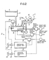
- a size viscosity controller in a fourth embodiment comprises a concentration control system and a temperature control system.
- a viscosity detector 23, a viscosity setting unit 24 are connected through a comparison point 20 to the input of a viscosity control unit 26.
- the viscosity detector 23 has a detecting head 23a provided within a cavity box 3 containing a size 4 and provides an electric viscosity signal A representing the viscosity of the size 4 contained in the cavity box 3.
- a first output terminal of the viscosity control unit 26 is connected to a control element 16 connected to a direct heat supply unit 12 of the concentration control system.
- the direct heat supply unit 12 supplies hot water or steam having large thermal energy and containing sufficient water through a supply line into te cavity box 3 to heat the size 4 contained in the cavity box 3 directly and to supply water to the same.
- a temperature detector 21 and an initial temperature setting unit 27 are connected through an add point 29 to the input of a temperature control unit 14 of the temperature control system.
- the output of the temperature control unit 14 is connected to a control element 17 connected to an indirect heat supply unit 13.
- the indirect heat supply unit 13 supplies steam or a heating medium heated by an electric heater through a supply path to a heat exchanger 18 connectd to the external wall of the cavity box 3 to heat the size 4 indirectly.
- a second output of the viscosity control unit 26 is connected to an add point 28, which is the most significant feature of the fourth embodiment.
- the viscosity of the size 4 tends to increase with time during the operation of the slasher 1 due to increase in the concentration attributable to the natural evaporation of water from the surface of the size 4, or the decrease of the temperature.
- the temperature control unit 14 controls the control element 17 on the basis of the difference between a temperature signal D representing the actual temperature of the size provided by the temperature detector 21, and a set temperature signal E representing a desired temperature provided by the initial temperature setting unit 27 to maintain the size 4 at the desired temperature by supplying the heating medium from the indirect heat supply unit 13 to the heat exchanger 18 so that the size is maintained at the desired viscosity in respect of temperature.
- the viscosity detector 23 detects the viscosity of the size 4 and applies a negative viscosity signal A proportional to the viscosity to the comparison point 20, where the viscosity sinal A representing the actual viscosity of the size 4 is compared with a set viscosiy signal B representing the desired viscosity.
- the viscosity control unit 26 controls the control element 16 so as to supply the heating medium, i.e., steam or hot water, to the cavity box 3 at a rate corresponding to the rate of natural evaporation of water from the cavity box 3.
- the viscosity control unit 26 provides a concentration control signal C1 proportional to the deviation to open the control element 16 further in an integral control mode or a proportional control mode to supply the heating medium at an increased rate from the direct heat supply unit 12 into the cavity box 3 to heat the size directly and to supply water to the size 4. Consequently, the viscosity of the size 4 is decreased automatically.
- the viscosity control unit 26 applies a temperature control signal C2 corresponding to the deviation to an add point 28 to raise the desired temperature temporarily for the temperature control system. Consequently, the temperature control unit 14 controls the control element 17 to supply the heating medium continuously from the indirect heat supply unit 13 to the heat exchanger 18 to adjust the temperature of the size 4 to the temporary desired temperature, which is higher than the initial desired temperature by a degree corresponding to the temperature control sinal C2.
- the viscosity of the size 4 contained in the cavity box 3 is decreased rapidly owing to the rapid increase of the temperature thereof resulting from the supply of heat from both the direct heat supply unit 12 and the indirect heat supply unit 13, and the decrease of the concentration resulting from the increased supply of the heating medium containing water from the direct heat supply unit 12.
- the temperature control unit 14 keeps the control element 17 inoperative not to supply heat from the indirect heat supply source to the size 4.
- a cooling medium may be supplied from a cooling medium supply unit 30 to the heat exchanger 18 to adjust the temperature of the size 4 to the temporary desired temperature.
- the viscosity is decreased rapidly by the viscosity reducing effect of the increased temperature and the concentration decreasing effect of the increased supply of the heating medium supplied by the direct heat supply unit 12, because the temporary desired temperature is higher than the initial desired temperature.
- the viscosity control unit 26 provides a concentration control signal C1 proportional to the deviation of the actual viscosity from the desired viscosity to control the control element 16 so that the rate of supply of the heating medium supply from the direct heat supply unit 12 to the cavity box 3 is decreased.
- the viscosity control unit 26 applies a temperature control signal C2 corresponding to the deviation to the add point 28 to lower the desired temperature for the temperature control system temporarily.
- the viscosity of the size 4 increases rapidly due to the sharp drop of the temperature of the size 4 caused by the combined effect of decrease in the rate of heat supply from the direct heat supply unit 12 and the indirect heat supply unit 13, and due to increase in the concentration of the size 4 resulting from the insufficient supply of water to the size 4 as compared with the rate of evaporation of water from the size caused by decrease in the rate of supply of the heating medium from the direct heat supply unit, namely, decrease in the rate of supply of water.
- a size viscosity controller in a fifth embodiment similarly to that in the fourth embodiment, comprises a concentration control system and a temperature control system.
- a viscosity control unit 26 is connnected to a control element 17 connected to an indirect heat supply unit 13, and a temperature control unit 14 is connected to a control element 16 connected to a direct heat supply unit 12.
- the viscosity control unit 26 applies a concentration control siganl C1 to reduce the variation of the deviation of the actual viscosity of the size 4 from the desired viscosity, namely, applies a plus output signal C1 if it receiveies the plus input signal. Accordingly, the amount of heat supplied from the indirect heat supply unit 13 is decreased with the decrease of variation of the deviation of the actual viscosity of the size 4 from the desired viscosity.
- the viscosity control unit 26 applies a temperature control signal C2 to an add point 28 to change an initial desired temperature for a temporary desired temperature which is higher than the former.
- the temperature control unit 14 controls the control element 16 to increase the rate of supply of heat from the direct heat supply unit 12 to the size 4 so that the temperature of the size 4 is adjusted to the temporary desired temperature.
- the amount of heat supplied by the direct heat supply unit 12 is increased by an increment equal to the sum of an amount of heat necessary for compensating the decrease of heat supplied by the indirect heat supply unit 13, and an amount of heat necessary for increasing the temperature of the size 4 to the temporary desired temperature which is higher than the initial desired temperature.
- the size 4 is heated by the increased heat supplied by the direct heat supply unit 12 and hence water is supplied at an increased rate to the size 4, so that the viscosity of the size 4 is decreased rapidly.
- the viscosity control unit 26 gives a concentration control signal C1 to reduce the variaion of the deviation of the actual viscosity of the size 4 from the desired viscosity, namely, applies a plus ouptput signal C1 when it receives the plus input signal to the control element 17 to supply heat from the indirect heat supply source 13 at an increased heat supply rate and, at the same time, the viscosity control unit 26 provides a temperature control siganl C2 corresponding to the deviation to change an initial desired temperature for a temporary desired temperture which is lower than the former.
- the amount of heat supplied by the direct heat supply unit 12 is decreased by a large decrement equal to the sum of an increment of heat supplied by the indirect heat supply unit 13 and an amount of heat to be curtailed to adjust the temperature of the size 4 to the temporary desired temperature lower than the initial desired temperture.
- the viscosity of the size 4 is increased rapidly by the sharp drop of the temperature of the size 4 caused by the curtailment of the amount of heat supplied by the direct heat supply unit 12, and the sharp increase of the concentration due to the curtailment of the amount of water supplied to the size 4.
- the temperature control unit 14 employs a cooling medium supply unit 30 to cool the size 4.
- the viscosity control unit 26 gives the concentration control signal C1 to supply a cooling medium from the cooling medium supply unit 30 to the heat exchanger 18 so that the heat supply rate of the direct heat supply unit 12, hence the water supply rate, is increased to promote the decrease of the viscosity.
- an initial viscosity may be the viscosity of the size 4 first supplied into the cavity box 3 and heated at the initial desired temperature. That is, a viscosity detected by the viscosity detector 33 in the initial stage of sizing operation after the temperature of the size 4 has been adjusted to the initial desired temperature set by the temperature setting unit 27 may be stored in memory means and may be used as a desired viscosity to be set the viscosity setting unit 24.
- a size viscosity controller in a sixth embodiment is provided with a special temperature setting unit 31.
- the temperature setting unit 31 comprises a set temperature deciding unit 32, an initial temperature setting unit 33, and a temperature difference deciding unit 34 for converting viscosity deviation into a a corresponding temperature difference.
- the input of the temperature difference deciding unit 34 is connected through a viscosity comparison point 20 to a desired viscosity setting unit 24 and a viscosity detector 23.
- the set temperature deciding unit 32 is connected through a temperature comparison point 22 to the input of a temperature control unit 14.
- the output of a temperature detector 21 is connected to the comparison point 22.
- the set temperature deciding unit 32 decides a set temperature in a temperature range between an upper limit temperature and a lower limit temperature predetermined by a set temperature range setting unit 35.
- the upper limit temperature is near and below the boiling point of the size 4, and the lower limit temperature is decided taking into consideration a temperature at which oils coating the surface of warp yarns of warp 7, and cotton wax are dissolvable in the size 4, namely, a temperature at which the size 4 is able to permeate the warp yarns of the warp 7.
- the initial temperature setting unit 33 sets an initial temperature appropriate to making the viscosity of th size 4 converge rapidly on a desired viscosity set by the viscosity setting unit 24.
- a signal representing the initial temperature set by the initial temperature setting unit 33 is given through the set temperature deciding unit 32 and a comparison point 22 to the temperature control unit 14.
- the temperature control unit 14 controls a control element 16 so that a direct heating medium, in this embodiment, steam, is supplied from a direct heat supply unit 12 at a maximum rate into a cavity box 3 containing the size 4 to heat the size 4.
- the tmperature detector 21 detects the temperature of the size 4 and applies a signal representing the actual temperature of the size 4 to the comparison point 22.
- the temperature control unit 14 controls the control element 16 on the basis of the deviation of the actual temperature of the size 4 from the initial temperature to regulate the rate of supply of steam so that the temperature of the size 4 approaches the initial temperature, and thereby the viscosity of the size 4 converges on the desired viscosity or a viscosity near the desired viscosity as the temperature approaches the initial temperature. Since steam is supplied as a direct heating medium to the cavity box 3 to control the temperature of the size 4, water, as well as heat, is supplied to the size 4 in heating the same. If the rate of supply of water in the form of steam coincides with the rate of evaporation of water from the cavity box 3, the concentration of the size 4 contained in the cavity box 3 is maintained substantially at a fixed value. Accordingly, the viscosity of the size 4 is maintained at the fixed value both by supplying water to the size 4 and by controlling the temperature of the size 4.
- the size 4 is maintained at the initial temperature.
- the desired viscosity is decided specially for the size 4 so that the warp yarns are sized at an optimum size pic-up.
- the comparison point 20 gives a temperature signal corresponding to the difference between the actual viscosity of the size 4 detected by the viscosity detector 23, and the desired viscosity set by the viscosity setting unit 24 to the temperature difference deciding unit 34.
- the temperature difference deciding unit 34 gives a temperature difference signal, in this case, a temperature increment signal, to the set tempeature deciding unit 32.
- the set temperature deciding unit 32 gives a signal representing a desired temperature obtained by adding a temperature represented by the tempeature increment signal to the initial set temperature to the temperature control unit 14.
- the temperatre control unit 14 controls the control element 16 to raise the temperature of the size 4 by supplying steam to the same.
- the temperature of the size 4 increases, the viscosity of the size 4 decreases. Since the higher the set temperature of the size 4, the greater the heat dissipation from the size 4, steam is supplied at an increased rate into the cavity box 3, and thereby the concentration of the size 4 tends to decrease.
- the viscosity of the size 4 is decreased by the combined effect of increase in the temperature of the size 4 and decrease in the concentration of the same, and the viscosity of the size is stabilized at the desired viscosity after the temperature of the size 4 has been increased by a temperature increment.
- the set temperature is lowered and the steam supply rate is decreased.
- the viscosity of the size 4 is increased by the combined effect of decrease in the temperature and decrease in the steam supply rate.
- the viscosity of the size 4 is stabilized at the desired viscosity after the temperature has dropped by a temperature decrement.
- the viscosity of the size is not necessarily increased even if the steam supply rate is increased to heat the size 4 to the raised set temperature, if the rate of evaporation of water from the size exceeds the rate of increase of water supplied by steam. Therefore, the cavity box 3 is designed so that the surface of the size 4 contained therein is comparatively small and heat is dissipated at a high rate from the walls thereof to reduce the evaporation of water from the size 4 and to increase the effective amount of water supplied to the size 4 by supplying steam into the cavity box 3.
- the viscosity of the size 4 can be controlled effectively through the control of the concentration.
- the viscosity of the size 4 can be decreased by the combined effect of the water supplied together with steam into the cavity box 3 and the increase of the temperature of the size 4 by heat of steam.
- the direct heating medium supplied by the direct heat supply unit 12 may be either steam or hot water depending on the set temperature of the size 4.
- a size viscosity controller in a seventh embodiment is provided with an indirect heat supply unit 13 employing an electric heater 13b, a cooling medium supply unit 13a having a water jacket 37 having an outlet port 36 and enclosing the cavity box 3, and control element 17b and 17a connected respectively to the electric heater 13b and a cooling medium supply unit 13a.
- a temperature control unit 14 controls the control element 17a according to the variation of the viscosity of the size 4, for example, in a proportional control made to regulae a current supplied to the electric heater 13b.
- the temperature control unit 14 controls the control element 17b so as to increase the current supplied to the electric heater 13b to raise the temperature of the size 4.
- the concentration of the size 4 tends to increase entailing increase in the viscosity of the size 4 due to increase in the rate of evaporation of waer from the size 4 when the temperature of the size 4 is increased, the effect of the evaporation of water on increase in the concentration of the size 4 contained in the cavity box 3 is insignificant, beacuse a new size 4 is supplied from time to time from a size supply tank 11 into the cavity box 3.
- the temperature control unit 14 controls the control element 17a so as to decrease the current supplied to the electric heater 13b according to the reduction of the viscosity, and controls the control element 17b ao as to supply water of alow temperature into the water jacket 37 to cool the size 4 contained in the cavity box 3 to lower temperature.
- viscosity of the size 4 is increased rapidly by the combined effect of natural decrease in temperature of the size 4 resulting from decrease in the current supplied to the electric heater 13b, the replenishment of the cavity box 3 with the size 4 of a temerature lower than that of the size 4 contained in the cavity box 3, supplied from the size supply tank 11, and the positive cooling of the size 4 by the low-temperature water supplied into the water jacket 37.
- the actual temerature of the size 4 is detected and the temperature of the size 4 is controlled accurately in a feedback control mode, however, the temperature of the size 4 may be controlled in an open loop control mode.
- either the direct heat supply unit 12 or the indirect heat source supply unit 13 is used selectively.
- a size viscosity controller in an eighth embodiment according to the present invention a direct heat supply unit 12 and an indirect heat supply source 13 are used simultaneously to cancel the deviation of the actual viscosity of the size 4 from a desired viscosity.
- the ratio in heat supply rate between the direct heat supply unit 12 and the indirect heat supply unit 13 is regulated according to the deviation by an operational control unit 25a instead of the selector switch 25 employed in the foregoing embodiments.
- the operational control unit 25a does not vary the ratio in heat supply rate between the direct heat supply unit 12 and the indirect heat supply unit 13 but varies the total amount of the direct and indirect heat or ratio in heat supply rate of the indirect heat supply unit 13.
- the operational control unit 25a decides the ratio in heat supply rate between the direct heat supply unit 12 and the indirect heat supply unit 13 on the basis of the temperature deviation given thereto by a temperature control unit 14 and the viscosity deviation given thereto by a viscosity control unit 15 taking into account the total amount of heat before controlling or the condition of use of the heat supplied by the direct heat supply unit 12 and the indirect heat supply unit 13 and controls a control element 16 connected to the direct heat supply unit 12 and a control element 17 connected to the indirect heat supply unit 13 so that direct heat and indirect heat are supplied at the calculated ratio.
Landscapes
- Engineering & Computer Science (AREA)
- Textile Engineering (AREA)
- Physics & Mathematics (AREA)
- General Physics & Mathematics (AREA)
- Automation & Control Theory (AREA)
- Warping, Beaming, Or Leasing (AREA)
- Treatment Of Fiber Materials (AREA)
- Physical Or Chemical Processes And Apparatus (AREA)
- Control Of Temperature (AREA)
- Coating Apparatus (AREA)
Applications Claiming Priority (6)
| Application Number | Priority Date | Filing Date | Title |
|---|---|---|---|
| JP15203188 | 1988-06-20 | ||
| JP152031/88 | 1988-06-20 | ||
| JP165902/88 | 1988-07-05 | ||
| JP16590288 | 1988-07-05 | ||
| JP25255788 | 1988-10-06 | ||
| JP252557/88 | 1988-10-06 |
Publications (3)
| Publication Number | Publication Date |
|---|---|
| EP0347752A2 true EP0347752A2 (de) | 1989-12-27 |
| EP0347752A3 EP0347752A3 (de) | 1991-02-06 |
| EP0347752B1 EP0347752B1 (de) | 1995-11-22 |
Family
ID=27320207
Family Applications (1)
| Application Number | Title | Priority Date | Filing Date |
|---|---|---|---|
| EP89110873A Expired - Lifetime EP0347752B1 (de) | 1988-06-20 | 1989-06-15 | Verfahren zur Steuerung der Leimviskosität und Steuergerät für eine Leimmaschine |
Country Status (5)
| Country | Link |
|---|---|
| US (1) | US4944078A (de) |
| EP (1) | EP0347752B1 (de) |
| JP (1) | JP2933946B2 (de) |
| KR (1) | KR910002287B1 (de) |
| DE (1) | DE68924872T2 (de) |
Cited By (3)
| Publication number | Priority date | Publication date | Assignee | Title |
|---|---|---|---|---|
| DE4332069A1 (de) * | 1993-09-21 | 1995-03-23 | Stahl Gmbh & Co Maschf | Anordnung zum Auftragen von Leim auf Buchblockrücken |
| EP1086827A1 (de) * | 1999-09-22 | 2001-03-28 | Grapha-Holding Ag | Einrichtung zur Konstanthaltung einer bestimmten Viskosität eines Klebstoffes für die Beleimung eines Buchblockrückens oder einer Buchdecke |
| EP2744877A4 (de) * | 2011-08-19 | 2015-05-06 | Gen Electric | Heizsystem und -verfahren für eine brennstoffaufschlämmung |
Families Citing this family (8)
| Publication number | Priority date | Publication date | Assignee | Title |
|---|---|---|---|---|
| US6395088B1 (en) | 1999-06-30 | 2002-05-28 | Gaston Systems, Inc. | Apparatus for applying foamed coating material to a traveling textile substrate |
| JP2002235272A (ja) * | 2001-02-02 | 2002-08-23 | Tsudakoma Corp | 経糸糊付け機 |
| US6814806B2 (en) | 2002-07-25 | 2004-11-09 | Gaston Systems Inc. | Controlled flow applicator |
| US7431771B2 (en) * | 2004-11-12 | 2008-10-07 | Gaston Systems, Inc. | Apparatus and method for applying a foamed composition to a dimensionally unstable traveling substrate |
| WO2010111355A1 (en) * | 2009-03-24 | 2010-09-30 | Norcross Corporation | In-line viscometer with no moving parts and methods and computer-readable media for maintaining a desired viscosity |
| DE102013201487B4 (de) | 2013-01-30 | 2021-11-11 | Cefla Deutschland Gmbh | Farbauftragvorrichtung und Verfahren zur Viskositätseinstellung |
| US11179744B2 (en) | 2018-11-13 | 2021-11-23 | Gaston Systems, Inc. | Segmented distribution assembly for distributing fluid to an applicator nozzle |
| CN120054845A (zh) * | 2025-04-27 | 2025-05-30 | 浙江晶科储能有限公司 | 二次电池的制备方法、二次电池、储能系统及用电设备 |
Family Cites Families (7)
| Publication number | Priority date | Publication date | Assignee | Title |
|---|---|---|---|---|
| GB657137A (en) * | 1947-11-19 | 1951-09-12 | Dominion Textile Co Ltd | Viscosity control in yarn sizing |
| US3095463A (en) * | 1958-03-12 | 1963-06-25 | Crucible Steel Co America | Temperature control apparatus |
| DE2919005A1 (de) * | 1979-05-11 | 1980-11-20 | Hirsekorn Kunststoff | Kabelaufspulvorrichtung |
| GB2051742B (en) * | 1979-06-28 | 1983-03-09 | Ciba Geigy Ag | Gelating solution dispensing |
| US4364157A (en) * | 1980-11-20 | 1982-12-21 | Cutts William H | Method for applying sizing to warp yarns |
| US4530876A (en) * | 1983-08-12 | 1985-07-23 | Ppg Industries, Inc. | Warp sizing composition, sized warp strands and process |
| US4793035A (en) * | 1987-09-28 | 1988-12-27 | E. I. Du Pont De Nemours And Company | Dynamic control of textile warp size add-on on a running slasher |
-
1989
- 1989-06-07 KR KR1019890007814A patent/KR910002287B1/ko not_active Expired
- 1989-06-09 US US07/363,989 patent/US4944078A/en not_active Expired - Fee Related
- 1989-06-09 JP JP1147002A patent/JP2933946B2/ja not_active Expired - Lifetime
- 1989-06-15 EP EP89110873A patent/EP0347752B1/de not_active Expired - Lifetime
- 1989-06-15 DE DE68924872T patent/DE68924872T2/de not_active Expired - Fee Related
Cited By (4)
| Publication number | Priority date | Publication date | Assignee | Title |
|---|---|---|---|---|
| DE4332069A1 (de) * | 1993-09-21 | 1995-03-23 | Stahl Gmbh & Co Maschf | Anordnung zum Auftragen von Leim auf Buchblockrücken |
| EP1086827A1 (de) * | 1999-09-22 | 2001-03-28 | Grapha-Holding Ag | Einrichtung zur Konstanthaltung einer bestimmten Viskosität eines Klebstoffes für die Beleimung eines Buchblockrückens oder einer Buchdecke |
| US6508881B1 (en) | 1999-09-22 | 2003-01-21 | Grapha-Holding Ag | Device for maintaining constant a certain viscosity of an adhesive for pasting the spine of an inner book or a book cover |
| EP2744877A4 (de) * | 2011-08-19 | 2015-05-06 | Gen Electric | Heizsystem und -verfahren für eine brennstoffaufschlämmung |
Also Published As
| Publication number | Publication date |
|---|---|
| KR900000520A (ko) | 1990-01-30 |
| DE68924872T2 (de) | 1996-05-02 |
| EP0347752B1 (de) | 1995-11-22 |
| JPH02191736A (ja) | 1990-07-27 |
| DE68924872D1 (de) | 1996-01-04 |
| US4944078A (en) | 1990-07-31 |
| KR910002287B1 (ko) | 1991-04-11 |
| EP0347752A3 (de) | 1991-02-06 |
| JP2933946B2 (ja) | 1999-08-16 |
Similar Documents
| Publication | Publication Date | Title |
|---|---|---|
| US4944078A (en) | Size viscosity control method and controller for slashers | |
| US20220042687A1 (en) | Controlled hydronic distribution system | |
| US5490449A (en) | Temperature controller for cooking appliance | |
| US5452687A (en) | Microprocessor-based boiler sequencer | |
| CA1231414A (en) | Method and apparatus for regulating a heating installation in premises including a plurality of heat generators | |
| CN112628721A (zh) | 锅炉湿态运行给水控制方法、装置及存储介质 | |
| CN111856986A (zh) | 用于控制流体分配系统的控制系统和方法 | |
| EP0027112B1 (de) | Verfahren und apparat zum regulieren der temperatur eines heizelements in einem warmwasserbereiter | |
| CN114754432B (zh) | 一种基于降温需冷量变化的冷冻水供给调控方法及系统 | |
| RU2150642C1 (ru) | Способ автоматического управления процессом сушки | |
| GB2222006A (en) | Space heating control | |
| TW507039B (en) | A method for controlling the paste concentration of a pasting machine for carrying out the pre-wetting to threads | |
| JPS6451253A (en) | Spindle temperature controlling method and device for machine tool | |
| US7608169B2 (en) | Apparatus and method for break recovery in a paper machine or other system | |
| CN120751669A (zh) | 液冷系统的控制方法、控制装置及介质 | |
| JP3184721B2 (ja) | 糊付機の糊液制御装置 | |
| SE518563C2 (sv) | Torkning av virke | |
| TW201821669A (zh) | 紡織設備與其熱能調控方法 | |
| CN120367666A (zh) | 燃煤机组的负荷控制方法及装置 | |
| CN121252555A (zh) | 基于动态温差反馈的相变储热系统调控方法和电子设备 | |
| JPH06313260A (ja) | 糊付機の糊粘度制御装置 | |
| CN121498107A (zh) | 基于相变材料的蓄热水箱系统及控温与节水方法、计算机设备 | |
| CN116219665A (zh) | 基于温速调节的染液工艺温度跟随控制方法 | |
| CN119560693A (zh) | 动力电池的热管理方法、装置、设备及存储介质 | |
| CA1219301A (en) | Rapid-response water heating and delivery system |
Legal Events
| Date | Code | Title | Description |
|---|---|---|---|
| PUAI | Public reference made under article 153(3) epc to a published international application that has entered the european phase |
Free format text: ORIGINAL CODE: 0009012 |
|
| AK | Designated contracting states |
Kind code of ref document: A2 Designated state(s): CH DE FR IT LI |
|
| PUAL | Search report despatched |
Free format text: ORIGINAL CODE: 0009013 |
|
| AK | Designated contracting states |
Kind code of ref document: A3 Designated state(s): CH DE FR IT LI |
|
| 17P | Request for examination filed |
Effective date: 19910710 |
|
| 17Q | First examination report despatched |
Effective date: 19930922 |
|
| GRAA | (expected) grant |
Free format text: ORIGINAL CODE: 0009210 |
|
| AK | Designated contracting states |
Kind code of ref document: B1 Designated state(s): CH DE FR IT LI |
|
| ITF | It: translation for a ep patent filed | ||
| REF | Corresponds to: |
Ref document number: 68924872 Country of ref document: DE Date of ref document: 19960104 |
|
| REG | Reference to a national code |
Ref country code: CH Ref legal event code: NV Representative=s name: BUECHEL & PARTNER AG PATENTBUERO |
|
| ET | Fr: translation filed | ||
| PGFP | Annual fee paid to national office [announced via postgrant information from national office to epo] |
Ref country code: FR Payment date: 19960611 Year of fee payment: 8 |
|
| PLBE | No opposition filed within time limit |
Free format text: ORIGINAL CODE: 0009261 |
|
| STAA | Information on the status of an ep patent application or granted ep patent |
Free format text: STATUS: NO OPPOSITION FILED WITHIN TIME LIMIT |
|
| 26N | No opposition filed | ||
| PG25 | Lapsed in a contracting state [announced via postgrant information from national office to epo] |
Ref country code: FR Free format text: LAPSE BECAUSE OF NON-PAYMENT OF DUE FEES Effective date: 19980227 |
|
| REG | Reference to a national code |
Ref country code: FR Ref legal event code: ST |
|
| REG | Reference to a national code |
Ref country code: FR Ref legal event code: ST |
|
| PGFP | Annual fee paid to national office [announced via postgrant information from national office to epo] |
Ref country code: CH Payment date: 20020617 Year of fee payment: 14 |
|
| PGFP | Annual fee paid to national office [announced via postgrant information from national office to epo] |
Ref country code: DE Payment date: 20020619 Year of fee payment: 14 |
|
| PG25 | Lapsed in a contracting state [announced via postgrant information from national office to epo] |
Ref country code: LI Free format text: LAPSE BECAUSE OF NON-PAYMENT OF DUE FEES Effective date: 20030630 Ref country code: CH Free format text: LAPSE BECAUSE OF NON-PAYMENT OF DUE FEES Effective date: 20030630 |
|
| PG25 | Lapsed in a contracting state [announced via postgrant information from national office to epo] |
Ref country code: DE Free format text: LAPSE BECAUSE OF NON-PAYMENT OF DUE FEES Effective date: 20040101 |
|
| REG | Reference to a national code |
Ref country code: CH Ref legal event code: PL |
|
| PG25 | Lapsed in a contracting state [announced via postgrant information from national office to epo] |
Ref country code: IT Free format text: LAPSE BECAUSE OF NON-PAYMENT OF DUE FEES;WARNING: LAPSES OF ITALIAN PATENTS WITH EFFECTIVE DATE BEFORE 2007 MAY HAVE OCCURRED AT ANY TIME BEFORE 2007. THE CORRECT EFFECTIVE DATE MAY BE DIFFERENT FROM THE ONE RECORDED. Effective date: 20050615 |