EP0346630A2 - Globale Verdrahtung durch Wegnahme von redundanten Wegen - Google Patents
Globale Verdrahtung durch Wegnahme von redundanten Wegen Download PDFInfo
- Publication number
- EP0346630A2 EP0346630A2 EP89108813A EP89108813A EP0346630A2 EP 0346630 A2 EP0346630 A2 EP 0346630A2 EP 89108813 A EP89108813 A EP 89108813A EP 89108813 A EP89108813 A EP 89108813A EP 0346630 A2 EP0346630 A2 EP 0346630A2
- Authority
- EP
- European Patent Office
- Prior art keywords
- net
- paths
- path
- spaces
- initial
- Prior art date
- Legal status (The legal status is an assumption and is not a legal conclusion. Google has not performed a legal analysis and makes no representation as to the accuracy of the status listed.)
- Ceased
Links
Images


Classifications
-
- G—PHYSICS
- G06—COMPUTING OR CALCULATING; COUNTING
- G06F—ELECTRIC DIGITAL DATA PROCESSING
- G06F30/00—Computer-aided design [CAD]
- G06F30/30—Circuit design
- G06F30/39—Circuit design at the physical level
- G06F30/394—Routing
-
- Y—GENERAL TAGGING OF NEW TECHNOLOGICAL DEVELOPMENTS; GENERAL TAGGING OF CROSS-SECTIONAL TECHNOLOGIES SPANNING OVER SEVERAL SECTIONS OF THE IPC; TECHNICAL SUBJECTS COVERED BY FORMER USPC CROSS-REFERENCE ART COLLECTIONS [XRACs] AND DIGESTS
- Y10—TECHNICAL SUBJECTS COVERED BY FORMER USPC
- Y10T—TECHNICAL SUBJECTS COVERED BY FORMER US CLASSIFICATION
- Y10T29/00—Metal working
- Y10T29/49—Method of mechanical manufacture
- Y10T29/49002—Electrical device making
- Y10T29/49117—Conductor or circuit manufacturing
- Y10T29/49124—On flat or curved insulated base, e.g., printed circuit, etc.
- Y10T29/49155—Manufacturing circuit on or in base
- Y10T29/49156—Manufacturing circuit on or in base with selective destruction of conductive paths
-
- Y—GENERAL TAGGING OF NEW TECHNOLOGICAL DEVELOPMENTS; GENERAL TAGGING OF CROSS-SECTIONAL TECHNOLOGIES SPANNING OVER SEVERAL SECTIONS OF THE IPC; TECHNICAL SUBJECTS COVERED BY FORMER USPC CROSS-REFERENCE ART COLLECTIONS [XRACs] AND DIGESTS
- Y10—TECHNICAL SUBJECTS COVERED BY FORMER USPC
- Y10T—TECHNICAL SUBJECTS COVERED BY FORMER US CLASSIFICATION
- Y10T29/00—Metal working
- Y10T29/49—Method of mechanical manufacture
- Y10T29/49002—Electrical device making
- Y10T29/49117—Conductor or circuit manufacturing
- Y10T29/49124—On flat or curved insulated base, e.g., printed circuit, etc.
- Y10T29/49155—Manufacturing circuit on or in base
- Y10T29/49162—Manufacturing circuit on or in base by using wire as conductive path
-
- Y—GENERAL TAGGING OF NEW TECHNOLOGICAL DEVELOPMENTS; GENERAL TAGGING OF CROSS-SECTIONAL TECHNOLOGIES SPANNING OVER SEVERAL SECTIONS OF THE IPC; TECHNICAL SUBJECTS COVERED BY FORMER USPC CROSS-REFERENCE ART COLLECTIONS [XRACs] AND DIGESTS
- Y10—TECHNICAL SUBJECTS COVERED BY FORMER USPC
- Y10T—TECHNICAL SUBJECTS COVERED BY FORMER US CLASSIFICATION
- Y10T29/00—Metal working
- Y10T29/49—Method of mechanical manufacture
- Y10T29/49764—Method of mechanical manufacture with testing or indicating
Definitions
- This invention describes a method of interconnecting nodes on a chip, or more generally nodes of any device. More specifically, this invention involves generating initial zones for nets whose nodes are to be interconnected. An initial zone is a subset of the total paths for interconnecting the nodes of a net, and contains redundant paths when more than one minimum length path can be used to connect any two nodes of the net. Redundant paths having the worst scores, which are a function of a comparison of supply and demand for path spaces, are then gradually deleted until there are no redundant paths.
- segment movers in the algorithms they employ for net reconfiguration.
- To reroute a net they first identify one particular segment (a straight section of wire running along a "column” or “row") as the one to be moved.
- wire traffic may be routed vertically on one or more planes and horizontally on other planes.
- the term “column” specifies a collection of parallel wire channels in the vertical direction, while a “row” specifies a collection of parallel wire channels in the horizontal direction. So, after a segment has been identified for potential movement, this segment is relocated to another parallel column or row, and then other pieces of wire are adjusted to reconnect the moved segment to the rest of the net. Finally, the new configuration is compared to the old and just one configuration is kept.
- the dependent adjustments of connecting wires can be handled in a relatively simplistic manner. This helps keep the computation time down, but can lead to excessive wire lengths and non-optimal solutions.
- a third difficulty is the additive nature of most maze-runners. That is, the first connection to be routed has no congestion to contend with, since no other connections have been routed. As more connections are routed, congestion increases and becomes a significant factor in routing additional nets. The last connections to be routed often have overwhelming congestion problems to contend with, which makes successful completion nearly impossible on difficult designs. This additive process favors the first connections, at the expense of the last connections, but there is no way to order connections to make sure they all can be routed. With just one algorithm for creating initial routings of nets, and for rerouting nets (if the maze-runner programs do this), the maze-runner programs are limited. Varying the procedures and scoring parameters during the run can reduce this limitation, but it cannot be entirely overcome.
- a Multichip LSI Routing Program COMPAS by Yoshi Sugiyama, Kazuhiro Ueda, Kenji Kani, and Masanori Teramoto, of Nippon Electric, in Review of the Electrical Communication Laboratories Volume 25, Numbers 5-6, May-June 1977, pp. 445-454, describes another global wiring program.
- this considers length constraints due to electrical characteristics when rerouting nets. Nets to be rerouted may be selected either from those which pass through crowded channels, or from long nets.
- Chen does initial routings of all nets, ignoring congestion, with a "Steiner Tree” approach.
- the net reconfiguration defines a rectangle enclosing points to be connected, inserts wires spanning the rectangle both vertically and horizontally through all the points to be connected, and then removes the most costly portions of loops until just essential portions remain.
- This invention describes a method for interconnecting nodes of a number of nets.
- This method comprises generating an initial zone for each of the nets.
- the initial zone can be any set of paths used for interconnecting the nodes of each net, but this initial zone contains redundant paths when more than one minimum length path can be used to interconnect any two nodes of any given net.
- the next step of this method is to determine the cumulative demand for path spaces created by the initial zones above.
- a net is selected from the above, and a number of redundant paths is selected from the selected net.
- the cumulative demand found above is compared with the supply of available path spaces in an area used by the redundant paths selected above.
- a score is determined with the score being a function of at least the above comparison.
- an area where demand for path spaces exceeds supply is selected.
- expanded zones are generated for each sub-net.
- the sub-net refers to that part of a net within the selected area and includes nodes formed as points at the intersection of remaining paths and the perimeter of the selected area.
- the term remaining paths refers to paths remaining after deletion of redundant paths as described in the above paragraph.
- An expanded zone is any set of paths used to interconnect nodes of each sub-net and includes redundant paths.
- the cumulative demand for path spaces needed in the selected area for expanded zones is determined. Then, a sub-net is selected in the selected area.
- a number of redundant paths of the expanded zone for the selected sub-net are selected. Then, the demand for path spaces is compared with the supply of available path spaces in the selected area. Then, a score for each of the redundant paths selected above is determined. This score is a function of at least the comparison described above. Next, a path is deleted from the selected redundant paths, and this path is the one with the worst score as determined above. This process is then repeated until each of the expanded zones in the area has no redundant paths. It must be remembered that the cumulative demand for path spaces is recalculated for each repetition of this process when a path is deleted. Next, the above process is repeated for other selected areas where demand for wire spaces exceeds supply. Finally, the nodes of each net are interconnected with undeleted paths if path spaces are available for the undeleted paths remaining.
- a node of one circuit may be tied to a node of a second circuit, and also to a node of a third circuit. If we assume no other nodes connect to the three just cited, a three point "net" has been logically specified.
- the logical statement of a chip is to specify all the different occurrences of circuit types to be used, for example, 230 3-way OR's, 560 4-way AND's, and so forth. Each individual circuit is given a unique name or number, plus a detailed listing of all the specific node connections, that is, nets, required.
- a physical design is a blueprint for a physical layout in which all of the basic circuits are precisely located (a process called “placement”), and in which all of the necessary net wiring connections are precisely located, (a process called “wire routing”).
- placement and “wire routing” is all done in accordance with whatever so called “ground rules” apply to the technology in use.
- the minimum distance between parallel wires is always specified.
- Wire routing normally subdivides into a two stage process: 1) “global wire routing", 2) “exact embedding.”
- Global wire routing generates an approximate routing for all nets without specifying specific tracks or specific points of transit from one wiring plane to another. Exact embedding provides exact physical location for every wire and intermediate transit node.
- the invention herein described is a new method for global wire routing which is, as can be seen, fundamental to almost all physical design of chips, cards, and boards.
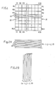
- FIG. 1 Shown in FIG. 1 is a circuit chip 10 which is divided into columns C1 through C15 and rows R1 through R15, so that each row has wire spaces for several horizontal wires and each column has wire spaces for several vertical wires.
- path spaces the equivalent of wire spaces will be referred to as "path spaces".
- the columns are in one or more planes while the rows are in other planes of the chip.
- vias are used to interconnect columns to rows.
- FIG. 2 is an expanded view of a row Rn (1 ⁇ n ⁇ 15) or a column Cn (1 ⁇ n ⁇ 15) with tracks 13 to which individual wires are ultimately assigned.
- each cell may contain an entire circuit, part of a circuit, or portions of several circuits.
- the locations of all circuits are known before global wiring begins.
- the term net is defined as a collection of points to be interconnected by, in this specific embodiment, a conductive path.
- a net can also include segments or paths used to interconnect the nodes.
- Global wiring of a net consists of connecting all the cells which contain points (see below) of the net into a common network of wires. The wires are routed along columns and rows, without deciding on exact track assignments. The final result of global wiring should not have more wires assigned at any spot in any column or row than can be accommodated.
- This model (FIG. 1) of the wiring area is very flexible. It is not necessary, for example, for all columns and rows to have the same capacities. Edge columns and rows, for example, may be quite different from other rows and columns if they contain I/O circuits.
- the ability to vary capacities dynamically during global wiring can be a powerful design procedure for some technologies which have variable width wiring bays. It is also possible to have entire areas of a chip dedicated to predesigned entities, such as RAM (Random Access Memory).
- RAM Random Access Memory
- the model of wiring spaces in the cells covered by a RAM can be set to zero, if desired, so no global wires are routed through the area. The model should match the detailed wiring approach, so the global wiring solution is easily handled by the detailed wiring programs.
- the global wiring procedure of this invention starts by defining an initial 'zone' for each net.
- the zone of a net is defined by the union of all currently permitted routings of that net.
- An initial zone is a subset of the total segments for interconnecting all the nodes of a particular net, in which every segment of said subset is either (1) irremovable, said irremovable segments being a part of every minimum path of the net in question, or (2) removable, in that every removable segment is part of at least one minimum path for the net in question, but is not part of every minimum path for that net.
- minimum path will normally be a minimum length path but it will be obvious to one skilled in the art that other criterion than line length may be involved in determining a most preferred path.
- minimum path we mean most preferred path for whatever problem is under attack.
- the preferred path could be, for example, the least cost path.
- An initial zone typically includes all permitted minimum length routings, minimizes parallelism and excludes unnecessary segments.
- Minimum length routings means that the minimum length of wire is used to interconnect the nodes of a corresponding net. If any more than the minimum length is used, then the path is not minimum length.
- permitted refers to those routings which the chip designer decides to include in the zone. This decision should be based on various anticipated overflow conditions.
- FIG. 3A shows a sample net, and its initial zone 30.
- the circles represent points (nodes) (35) of the net, and each line (36) represents a wire which may be used as part of a final routing.
- FIG. 3A thus shows all of the minimum length permitted routes (paths), which may be used to interconnect points (nodes) 35.
- Using minimum length routes means that there is neither unnecessary parallelism nor unnecessary segments.
- the net reconfiguration process (to be described below) is primarily subtractive, starts with initial zones and reduces the zones of nets until each net has just one possible routing left. Evaluation of any particular net during the reconfiguration phase takes into account the current zones of all other overlapping nets.
- One of the primary inputs to the global wiring of this invention is a list of points, or cells, which must be connected for each net.
- This invention creates an initial zone for each net. Very simple nets may have their final routings defined as their initial zones, and their zone definition will not change.
- An example of a routing or path interconnecting the points 35 of a net is shown by the dark line in FIG. 3A. This path, without other permissible routes or paths, is shown more clearly in the box labelled 32 at the bottom of FIG. 3B.
- segments 34 are also shown in FIG. 3B.
- the vias are used to interconnect segments on different planes of a chip. While the number 32 is also used to indicate a segment, this number more specifically indicates an irremovable segment which means that it is a segment which is a part of every minimum path of FIG. 3A. The removable paths, indicated by the number 34, means that this segment is a part of at least one minimum path of FIG. 3A. Notice also that the terms: "routing(s)", “route(s)” and “path(s)” are used interchangeably in this application. Most nets will have initial zones containing more possibilities, and later processing will eliminate all but one of these routings for each net.
- Two points of a net can have an initial zone which is a rectangle (see 37 or 38 of FIG. 3A) with the points in opposite corners, or a single line if the points are in one column or row (see 39 of FIG. 3A). Nets with more than two points, such as 30 in FIG. 3A, may be a combination of rectangles and lines.
- An initial zone called a 'hybrid zone', has a rectangle where two sides (see 45 of FIG. 4) are mandatory parts of the final routing, but there is a choice of paths between the other two sides.
- a hybrid zone is shown in FIG. 4. In the discussion below, "rectangle" refers to a normal zone which has many options for routing, and the hybrid zone exceptions are always specifically noted.
- the initial zone of each net should ideally be the union of all the minimum length routes which could be used in connecting the points of the net. However, with some nets all minimum length routes are not permitted routes as in the hybrid zone shown in FIG. 4. Minimum length routing is desirable for performance of the finished circuit. Minimum length routing also solves congestion problems more quickly. Parallelism within a net should be minimized during creation of each initial zone, or else some routings which are not of minimum length will be possible. However, if a zone is not minimal at the start, the program used in this invention will still operate successfully, and may select a minimal configuration as its final solution.
- Initial zone creation requires some arbitrary choices. A net determining a rectangle would define an initial zone with both horizontal and vertical routings, although actually, one might choose one direction or the other depending upon related considerations. For example, a certain chip might have fewer vertical channels than horizontal channels. Hence, one would work harder to avoid vertical overflows. The choice could be based on reasonable factors such as length, expected congestion, and location on the chip. However, there will always be some arbitrariness in these initial zones, since it cannot be known at the start which choice is going to turn out best for design of the whole chip. The choice involves deciding which routes are to be permitted or included in the initial zone. This arbitrariness is not too harmful, since there are many opportunities later to overcome the effects of imperfect initial zones.
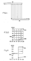
- FIG. 5 there are 5 columns shown (C6 - C10), plus 6 rows (R8 - R13). Node 35A occurs in column C6, Row R10. Node 35B occurs in column C8, Row R8. Node 35C occurs in column C10, row R13.
- a "zone” is simply as shown in FIG. 5, where a line has been assigned to every column and every row, showing all possible routes for connecting the three nodes. To obtain what we term the "initial zones", certain lines in the zone are removed as shown in FIG. 6.
- Rows R8 and R9 have been completely dropped and rows R11, R12, and R13 partially dropped, columns C6, C7 and C9 have been completely dropped, and part of column C10. It will be obvious to anyone skilled in the art that (with the exception of column C9), none of the dropped parts would appear in a minimal wire routing of the net in question.
- An alternative "initial zone" is shown in FIG. 7.
- FIG. 7 differs from FIG. 6 in that all of rows R11 and R12 have now been dropped, and part of column C9 has been restored.
- FIG. 8 shows a third possible "initial zone”.
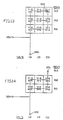
- FIG. 9 shows three circles (intersection of row R13 and column C10, intersection of row R13 and column C9, and intersection of row R10 and column C9). Each of the three circles represents a "via" which has been added to accomplish the wire routing shown.
- the routing shown in FIG. 9 could be reached, as will be obvious to one skilled in the art, by taking away from the initial zones shown in FIGS. 7 and 8, but not from FIG. 6. Hence, if our initial zone was either the one shown in FIG. 7 or 8, a solution requiring three additional vias might be required.
- FIG. 10 shows a routing that might be reached from FIG. 6.
- FIG. 10 shows two circles (at the intersection of row R11 and column C10 and at the intersection of row R11 and column C8). It will be obvious that only two additional vias are required for the routing shown in FIG. 10. It is further obvious, that no routing reached from FIG. 6 will require more than two additional vias, whereas the routing shown in FIG. 9 (reached from either the initial zones shown in FIGS. 7 or 8) requires three additional vias. If for the chip in question, there was great advantage in keeping down the total number of vias, then the initial zone shown in FIG. 6 might be selected.
- the "taking away” process is the removal of certain of the removable segments until a point is reached where no further segments can be removed without disconnecting the net.
- the unique feature of the taking away process of this invention is the method by which it is done. Let us describe that method using the initial zone shown in FIG. 6 as one tutorial example.
- the left to right scoring in the three boxes from columns C8 to C10 in row R10 may now be updated to V-6,H-3; V-3, H-9; V-1,H-5; if this is the scoring left after the removal cited.
- wire crossings are generally counted at the edges of cells, but can be counted at cell centers.
- the number of available wiring spaces at each location is determined before global wiring starts. After all nets are initially routed, the numbers of wires passing these points is known. This invention then compares the available spaces ("supply") to the number of passing wires ("demand”) to determine where the overall configuration of wires must be modified.
- zones After initial zones are defined for all nets, their cumulative wiring demand is determined. Where a zone consists of a single connection wire, each of the global cells through which the wire passes is assessed a demand for wiring space sufficient for that wire. Where a zone consists of a rectangle, its demand is calculated as if the net had several wires running in parallel horizontally across the rectangle and several wires running vertically across the rectangle. Each of the global cells within the rectangle contains both vertical and horizontal wires for the net. Zones of most nets include both rectangles and wire segments, so some cell scores are affected one way and some the other. In some cases, as we have noted above, it is also useful to score "vias", or corners in paths.
- Congestion numbers for the design can be generated by subtracting the demand numbers from the supply numbers in each cell. Areas where the demand exceeds the supply will have negative results, indicating overflow conditions. Analysis of vertical and horizontal overflows will reveal that some areas have congestion only on one plane. Congestion measures can be useful to designers in controlling the global wiring process, and can be used internally by the programs to control a variety of actions. Later in the discussion, we shall show computer run results for a complete problem solution including a diagram showing the scoring after all initial zones have been overlaid. All the basic features of the invention will be illustrated.
- One variation of the scoring process treats "committed” and “optional” demand separately. That is, some of the wires in a zone may have no alternative, and so their demand can be called “committed”. Other wires have alternatives, so they can be called “optional”. If most of the demand in a cell is "committed", the overflow problem there is more severe than if the demand is mostly “optional”. By taking this into account when accumulating penalty weights for all cells in a path, the rerouting process can be directed to attack the more difficult congestion problems. When choices are made, optional demand counts are decreased and some committed demand counts may be increased.
- the "taking away” process removes extra paths from nets, until there is just one routing left for each net. After the initial scoring is completed, there are probably many areas of severe congestion. This is only a temporary situation, and somewhat artificial, since many nets have multiple paths.
- This invention processes all nets which have extra paths, perhaps using a different order for each pass through the nets.
- the extra paths of a net refers to a net which still has multiple choices available as to which path will ultimately be chosen for final routing.
- Each net is examined to see which of its redundant paths contributes most to congestion problems, and that path is then eliminated. Where more than one path are equally bad, the decision about which to eliminate can often be postponed, so decisions made about other nets can be taken into account.
- nets which are extremely flexible, with more possible routings may have all decisions postponed until more constrained nets have selected their best paths. Whenever a path or portion of a path is eliminated, the scores for the affected cells are updated.
- Evaluation of a path, or a portion of a path must take into account the overflow situation in each of the cells along the path.
- Overflow is calculated by subtracting demand from supply. Simply accumulating the overflow values would not provide a good basis for comparison to other paths, so a set of penalty values, or weights, are used.
- the weights can be changed for a variety of reasons during global wiring, but heavy penalties are usually given for severe overflows, lighter penalties for small overflows, still smaller penalties for cases where supply is barely adequate, and no penalties where supply significantly exceeds demand. Note that it is a particular path which is being scored, so a line passing through a cell may be penalized for its horizontal or vertical contribution but not both, even if the zone of the net has both vertical and horizontal paths running through the cell.
- Total scores for paths can also include penalties for vias and other factors. The path gets a total score which can be directly compared to other path scores, so the worst can be easily identified.
- the initial zone includes parallel wires only vertically or horizontally, but not both (see “horizontal/vertical biasing” below).
- the taking away only scores the parallel paths at opposite extremes (top and bottom or extreme left and extreme right), so when a path is eliminated the rectangle shrinks. This is much easier to program than approaches which might fragment rectangles in successive passes, and this also runs faster. Elimination of a minimal path from the middle of a hybrid zone does not fragment the zone in the same way as a normal rectangle because two of the hybrid zone sides must be retained in the final configuration. Hybrid zones can more easily have all possibilities considered and any one of the excess parallel paths across the zone might be eliminated without complicating the bookkeeping too much.
- the routings which remain after the initial taking away process may be a satisfactory final wiring solution. This would be ideal for circuit performance, since all routings would be minimum length. However, this is not expected on any difficult designs. If it occurs there are probably extra wiring spaces, and the design is very easy. It is expected that the initial taking away will handle "easy” congestion problems, and leave “difficult” congestion problems at some spots on the chip which can only be solved by adding more lengths of wire to some nets.
- the emphasis of the invention changes to attacking the remaining overflow areas directly. This involves recreating some of the net zones (as described below), and then using the taking away procedure again to find new routings for those nets.
- a "box” can be created around any set of adjacent cells, usually creating a rectangle around a problem area.
- a box might contain one important overflow, several overflows, or any other supply versus demand situations.
- the region within the box is where rerouting occurs.
- the box may be "small” or “big”, depending on the number of non-problem cells which are included to facilitate rerouting. Focusing on small areas by using boxes limits the amount of work that must be done by the program, which helps keep run time down.
- the box is a very powerful and flexible concept, with a variety of uses.
- Zones in the regions outside the box are held constant and are not changed. By isolating the region to be attacked, a new set of expanded zones totally within the box can be created, and a new taking away process undertaken, focusing directly on the overflows captured by the box. This insures that no changes will affect regions outside.
- the box approach can be used to keep congestion problems from simply oscillating between two nearby locations, and to keep the solution process constantly moving forward.
- Zone creation can deliberately constrain rerouting, to solve problems without introducing too much additional wire, and to avoid convoluted paths with many bends.
- Additional wire refers to non-minimum length routings of nets. Constraints are valuable early in the process, since introduction of too much wire can make later improvements more difficult.
- Some problem areas may contain overflows on just the horizontal or just the vertical plane. In these cases, putting emphasis on just one plane can be quite effective.
- rectangular zones can be created with many parallel horizontal wires and just two verticals along the edges. This would be appropriate for solving a horizontal overflow problem. To emphasize the other plane, the same rectangle could have many vertical wires, and horizontals at just top and bottom.
- the horizontal overflows very much exceed the vertical ones, because the configuration of the initial zones has maximized the horizontal choices, so as to minimize (as explained above) the number of vias required for the majority of nets.
- FIG. 19 we see the vertical overflows left after the taking away process.
- FIG. 20 the horizontal overflows are shown after the taking away process. There are substantially fewer horizontal than vertical overflows at this stage of the solution, because as indicated above, the horizontal side was favored in the forming of the initial zones for nets.
- FIG. 21 some of the boxes surrounding overflows which were generated by the computer are shown.
- the different numbers serve as names of the boxes in question and identify the position of the cells therein.
- FIG. 22 the vertical overflows created by the forming of expanded zones inside boxes are shown.
- FIG. 23 the horizontal overflows resulting from the expanded zones inside the boxes are shown. Because there were so many more vertical overflows than horizontal after the original taking away process, the program now maximizes vertical choices for the taking away which will now take place inside the boxes.
- FIG. 24 the vertical overflows after the taking away inside the boxes are shown. As can be seen, this step has reduced the vertical overflows from 692 to 391.
- FIG. 25 the horizontal overflows after the taking away inside the boxes are shown. Since the primary focus was on the elimination of vertical overflows, no improvement is registered here. The new position achieved differs greatly from the overflow position before the run.
- FIGS. 26 and 27 show that the resulting overflows obtained are reduced to 279 on the vertical side, and 186 on the horizontal side. A box run was then made favoring the horizontal side. The results are shown in FIGS. 28 and 29, the horizontal overflows reduced to 95.
- the strategy of changing the target of attack is normally an effective tactic in such large scale problem solving, since continual changing of positions enables the basic optimizing machinery to operate at maximum efficiency.
- Some boxes were also formed by the program in later runs as shown in the example of FIG.30.
- the tactic of shifting targets can be enhanced in a variety of ways.
- FIGS. 31 and 32 show the overflows obtained after bias runs of -1 or -2 followed by a new bias run. It should be emphasized that the only algorithms employed are the ones presented in the current invention, which adopts easily to the shifting target tactic.
- FIGS 33. and 34 were conducted, and the resultant overflow values shown in FIGS 33. and 34 were obtained. It will be noted that the method is designed so far as possible to eliminate overflows without introducing unnecessary parallelism. If for example, the overflows are surrounded by underflows and no nets to this point have been routed circuitously, then it will be obvious to the reader that if a small number of overflows exist, having resisted the current approach, we can follow slightly circuitous paths on a small number of nets (given the substantial underflows), and eliminate all overflows rather easily.
- FIG. 35 shows some boxes formed by the program in further runs.
- FIG. 36 and 37 display the vertical and horizontal positions reached after box runs using adjusted scores. There are at this point 36 vertical overflows and 17 horizontal overflows.
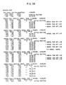
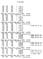
- FIGS. 38 to 44 provide a succinct summary of all the runs mentioned above.
- the transition from the methods of the invention to the segment moving runs can be seen on FIG. 42.
- the current status of the software embodiment of the invention led to a number of superfluous reruns. This can be corrected and does not bear upon the basic invention. All the runs were made during a single day, November 15, 1987. Although the current state of the software required multiple runs, the introduction of a relatively obvious control would enable the whole series of runs to be accomplished in a simple run.
- FIGS. 45 and 46 show the final position reached without vertical or horizontal overflows.
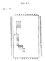
- FIG. 47 shows the initial zone for one (net #164) of the 5000 nets. This would have contributed to the totals shown in FIGS. 17 and 18.
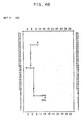
- FIG. 48 shows the net after the taking away process has been completed. This would have contributed to the final totals shown in FIGS. 19 and 20.
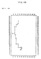
- FIG. 49 shows the final routing corresponding to net #164. Notice, in FIG 49, that although additional vias were eventually introduced, there is no unnecessary parallelism in this final routing.
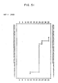
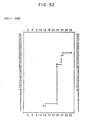
- FIGS. 50, 51, and 52 show the same three stages for net 3409; and FIGS. 53, 54, and 55 show the same three stages for net 1985. The "p's" represent the nodes in the different nets.
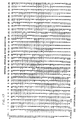
- FIG. 56A Shown in FIG. 56A is a selected area 60 where demand for path spaces exceeds supply even after the creation of initial zones and deletion of redundant paths from these initial zones. Also shown is path 54 and a sub-net containing nodes 53A, 53B and 53C. Node 53B is a node of a net that falls within selected area 60, while nodes 53A and 53C are nodes formed as points at the intersection of path 54 and the perimeter of the selected area.
- FIG. 56B Shown in FIG. 56B is an expanded zone 55 and selected area 60 for the sub-net containing nodes 53A, 53B and 53C. The deletion of paths from the expanded zones is described above.
Landscapes
- Engineering & Computer Science (AREA)
- Computer Hardware Design (AREA)
- Physics & Mathematics (AREA)
- Theoretical Computer Science (AREA)
- Computer Networks & Wireless Communication (AREA)
- Evolutionary Computation (AREA)
- Geometry (AREA)
- General Engineering & Computer Science (AREA)
- General Physics & Mathematics (AREA)
- Design And Manufacture Of Integrated Circuits (AREA)
- Electric Propulsion And Braking For Vehicles (AREA)
Applications Claiming Priority (2)
| Application Number | Priority Date | Filing Date | Title |
|---|---|---|---|
| US07/205,138 US4831725A (en) | 1988-06-10 | 1988-06-10 | Global wiring by removal of redundant paths |
| US205138 | 1988-06-10 |
Publications (2)
| Publication Number | Publication Date |
|---|---|
| EP0346630A2 true EP0346630A2 (de) | 1989-12-20 |
| EP0346630A3 EP0346630A3 (de) | 1991-06-12 |
Family
ID=22760959
Family Applications (1)
| Application Number | Title | Priority Date | Filing Date |
|---|---|---|---|
| EP19890108813 Ceased EP0346630A3 (de) | 1988-06-10 | 1989-05-17 | Globale Verdrahtung durch Wegnahme von redundanten Wegen |
Country Status (4)
| Country | Link |
|---|---|
| US (1) | US4831725A (de) |
| EP (1) | EP0346630A3 (de) |
| JP (1) | JPH077427B2 (de) |
| CA (1) | CA1290863C (de) |
Cited By (1)
| Publication number | Priority date | Publication date | Assignee | Title |
|---|---|---|---|---|
| DE10100068C1 (de) * | 2001-01-02 | 2002-05-08 | Siemens Ag | Verfahren zum Aufbau eines Overlay-Netzes |
Families Citing this family (42)
| Publication number | Priority date | Publication date | Assignee | Title |
|---|---|---|---|---|
| US5295082A (en) * | 1989-02-22 | 1994-03-15 | The Boeing Company | Efficient method for multichip module interconnect |
| US5074037A (en) * | 1989-12-01 | 1991-12-24 | Oerlikon-Contraves Ag | Process for producing electrical connections on a universal substrate |
| JP3052519B2 (ja) * | 1992-01-14 | 2000-06-12 | 日本電気株式会社 | 集積回路の電源配線設計方法 |
| US5495419A (en) * | 1994-04-19 | 1996-02-27 | Lsi Logic Corporation | Integrated circuit physical design automation system utilizing optimization process decomposition and parallel processing |
| US5638288A (en) * | 1994-08-24 | 1997-06-10 | Lsi Logic Corporation | Separable cells having wiring channels for routing signals between surrounding cells |
| WO1996024904A1 (en) * | 1995-02-07 | 1996-08-15 | Silicon Valley Research, Inc. | Integrated circuit layout |
| US5638290A (en) * | 1995-04-06 | 1997-06-10 | Vlsi Technology, Inc. | Method for eliminating a false critical path in a logic circuit |
| US5831863A (en) * | 1996-06-28 | 1998-11-03 | Lsi Logic Corporation | Advanced modular cell placement system with wire length driven affinity system |
| US5963455A (en) * | 1996-06-28 | 1999-10-05 | Lsi Logic Corporation | Advanced modular cell placement system with functional sieve optimization technique |
| US5914888A (en) * | 1996-06-28 | 1999-06-22 | Lsi Logic Corporation | Advanced modular cell placement system with coarse overflow remover |
| US5870311A (en) * | 1996-06-28 | 1999-02-09 | Lsi Logic Corporation | Advanced modular cell placement system with fast procedure for finding a levelizing cut point |
| US6026223A (en) * | 1996-06-28 | 2000-02-15 | Scepanovic; Ranko | Advanced modular cell placement system with overlap remover with minimal noise |
| US6030110A (en) * | 1996-06-28 | 2000-02-29 | Lsi Logic Corporation | Advanced modular cell placement system with median control and increase in resolution |
| US5870312A (en) * | 1996-06-28 | 1999-02-09 | Lsi Logic Corporation | Advanced modular cell placement system with dispersion-driven levelizing system |
| US6085032A (en) * | 1996-06-28 | 2000-07-04 | Lsi Logic Corporation | Advanced modular cell placement system with sinusoidal optimization |
| US5835381A (en) * | 1996-06-28 | 1998-11-10 | Lsi Logic Corporation | Advanced modular cell placement system with minimizing maximal cut driven affinity system |
| US5808899A (en) * | 1996-06-28 | 1998-09-15 | Lsi Logic Corporation | Advanced modular cell placement system with cell placement crystallization |
| US5892688A (en) * | 1996-06-28 | 1999-04-06 | Lsi Logic Corporation | Advanced modular cell placement system with iterative one dimensional preplacement optimization |
| US5812740A (en) * | 1996-06-28 | 1998-09-22 | Lsi Logic Corporation | Advanced modular cell placement system with neighborhood system driven optimization |
| US5867398A (en) * | 1996-06-28 | 1999-02-02 | Lsi Logic Corporation | Advanced modular cell placement system with density driven capacity penalty system |
| US5844811A (en) * | 1996-06-28 | 1998-12-01 | Lsi Logic Corporation | Advanced modular cell placement system with universal affinity driven discrete placement optimization |
| US6067409A (en) * | 1996-06-28 | 2000-05-23 | Lsi Logic Corporation | Advanced modular cell placement system |
| US5872718A (en) * | 1996-06-28 | 1999-02-16 | Lsi Logic Corporation | Advanced modular cell placement system |
| US6026224A (en) * | 1996-11-20 | 2000-02-15 | International Business Machines Corporation | Redundant vias |
| US6412102B1 (en) * | 1998-07-22 | 2002-06-25 | Lsi Logic Corporation | Wire routing optimization |
| US7107564B1 (en) * | 2001-06-03 | 2006-09-12 | Cadence Design Systems, Inc. | Method and apparatus for routing a set of nets |
| GB2393533A (en) * | 2002-09-27 | 2004-03-31 | Zuken Ltd | Routing of interconnected regions e.g. of electrical circuits |
| US6907588B2 (en) * | 2002-12-31 | 2005-06-14 | Lsi Logic Corporation | Congestion estimation for register transfer level code |
| US7096445B1 (en) | 2003-01-14 | 2006-08-22 | Cadence Design Systems, Inc. | Non-orthogonal structures and space tiles for layout, placement, and routing of an integrated circuit |
| US7676781B1 (en) | 2003-01-14 | 2010-03-09 | Cadence Design Systems, Inc. | Method and mechanism for implementing a minimum spanning tree |
| US7100128B1 (en) * | 2003-01-14 | 2006-08-29 | Cadence Design Systems, Inc. | Zone tree method and mechanism |
| US6941528B2 (en) | 2003-08-28 | 2005-09-06 | International Business Machines Corporation | Use of a layout-optimization tool to increase the yield and reliability of VLSI designs |
| US20050048677A1 (en) * | 2003-08-29 | 2005-03-03 | International Business Machines Corporation | The use of a layout-optimization tool to increase the yield and reliability of vlsi designs |
| US7376926B1 (en) * | 2005-04-29 | 2008-05-20 | Xilinx, Inc. | Run-time efficient methods for routing large multi-fanout nets |
| US7308669B2 (en) * | 2005-05-18 | 2007-12-11 | International Business Machines Corporation | Use of redundant routes to increase the yield and reliability of a VLSI layout |
| US7661085B2 (en) * | 2007-07-23 | 2010-02-09 | Board Of Regents, The University Of Texas System | Method and system for performing global routing on an integrated circuit design |
| CA2643615A1 (en) * | 2007-11-09 | 2009-05-09 | Truth Hardware Corporation | Positive action lock for sliding windows |
| US8205934B2 (en) * | 2008-03-17 | 2012-06-26 | Alite Designs, Inc. | Portable chair |
| US8001514B2 (en) * | 2008-04-23 | 2011-08-16 | Synopsys, Inc. | Method and apparatus for computing a detailed routability estimation |
| US7898286B2 (en) * | 2009-02-11 | 2011-03-01 | International Business Machines Corporation | Critical path redundant logic for mitigation of hardware across chip variation |
| US11120171B2 (en) * | 2019-09-13 | 2021-09-14 | Mccormick Systems Llc. | System and method for construction cost estimation for non-computer aided design (CAD) files |
| CN117710516B (zh) * | 2023-08-28 | 2024-10-11 | 荣耀终端有限公司 | 路网生成方法、路网生成装置、电子设备及存储介质 |
Family Cites Families (11)
| Publication number | Priority date | Publication date | Assignee | Title |
|---|---|---|---|---|
| US3028659A (en) * | 1957-12-27 | 1962-04-10 | Bosch Arma Corp | Storage matrix |
| DE1266353B (de) * | 1964-03-13 | 1968-04-18 | Bbc Brown Boveri & Cie | Matrixfoermige Anordnung von Oxydschichtdioden zur Verwendung als manipulierbarer Festwertspeicher oder Informationsumsetzer |
| US3378920A (en) * | 1966-01-26 | 1968-04-23 | Air Force Usa | Method for producing an interconnection matrix |
| US4484292A (en) * | 1981-06-12 | 1984-11-20 | International Business Machines Corporation | High speed machine for the physical design of very large scale integrated circuits |
| US4631100A (en) * | 1983-01-10 | 1986-12-23 | Pellegrino Peter P | Method and apparatus for mass producing printed circuit boards |
| US4615011A (en) * | 1983-12-19 | 1986-09-30 | Ibm | Iterative method for establishing connections and resulting product |
| US4713773A (en) * | 1984-08-10 | 1987-12-15 | International Business Machine Corporation | Method for distributing wire load in a multilayer package and the resulting product |
| JPS61199166A (ja) * | 1985-03-01 | 1986-09-03 | Nec Corp | 配線経路探索装置 |
| US4613941A (en) * | 1985-07-02 | 1986-09-23 | The United States Of America As Represented By The Secretary Of The Army | Routing method in computer aided customization of a two level automated universal array |
| US4742471A (en) * | 1985-10-31 | 1988-05-03 | International Business Machines Corporation | Method for improving wirability of master-image DCVS chips |
| US4786613A (en) * | 1987-02-24 | 1988-11-22 | International Business Machines Corporation | Method of combining gate array and standard cell circuits on a common semiconductor chip |
-
1988
- 1988-06-10 US US07/205,138 patent/US4831725A/en not_active Expired - Fee Related
-
1989
- 1989-04-28 JP JP1107911A patent/JPH077427B2/ja not_active Expired - Lifetime
- 1989-05-03 CA CA000598581A patent/CA1290863C/en not_active Expired - Lifetime
- 1989-05-17 EP EP19890108813 patent/EP0346630A3/de not_active Ceased
Cited By (1)
| Publication number | Priority date | Publication date | Assignee | Title |
|---|---|---|---|---|
| DE10100068C1 (de) * | 2001-01-02 | 2002-05-08 | Siemens Ag | Verfahren zum Aufbau eines Overlay-Netzes |
Also Published As
| Publication number | Publication date |
|---|---|
| US4831725A (en) | 1989-05-23 |
| JPH077427B2 (ja) | 1995-01-30 |
| EP0346630A3 (de) | 1991-06-12 |
| CA1290863C (en) | 1991-10-15 |
| JPH01320582A (ja) | 1989-12-26 |
Similar Documents
| Publication | Publication Date | Title |
|---|---|---|
| US4831725A (en) | Global wiring by removal of redundant paths | |
| EP0145925B1 (de) | Iteratives Verfahren zur Feststellung von Verbindungen zwischen Knoten und resultierendes Produkt | |
| US6763512B2 (en) | Detailed method for routing connections using tile expansion techniques and associated methods for designing and manufacturing VLSI circuits | |
| US5856927A (en) | Method for automatically routing circuits of very large scale integration (VLSI) | |
| Shin et al. | A detailed router based on incremental routing modifications: Mighty | |
| KR0153392B1 (ko) | Lsi용 상호접속 배선 설계 방법 | |
| US5657242A (en) | Method of determining routes for a plurality of wiring connections and a circuit board produced by such a method | |
| Dees et al. | Automated rip-up and reroute techniques | |
| US6609237B1 (en) | Routing path finding method for automated routing/designing process and computer-readable storage medium having stored thereon routing path finding program | |
| US6353918B1 (en) | Interconnection routing system | |
| EP0133466A2 (de) | Gleichzeitige Plazierung und Verbindung von VLSI-Chips | |
| JPS62128166A (ja) | 複数の集積回路エレメントの配置を決定する方法 | |
| EP0125537B1 (de) | Verfahren zum Anordnen einer Mehrzahl von Leitersegmenten in einer "Bai" zusammengesetzt aus Leiterkanälen | |
| WO1997034316A9 (en) | Interconnection routing system | |
| Linsker | An iterative-improvement penalty-function-driven wire routing system | |
| Krohn | An over-cell gate array channel router | |
| US6532580B1 (en) | In-place method for inserting repeater buffers in an integrated circuit | |
| US6880143B1 (en) | Method for eliminating via blocking in an IC design | |
| US6615401B1 (en) | Blocked net buffer insertion | |
| JP2006065403A (ja) | 自動設計方法、自動設計プログラム及び半導体集積回路 | |
| Cha et al. | A simple and effective greedy multilayer router for MCMs | |
| US6408426B1 (en) | Method for determining locations of interconnect repeater farms during physical design of integrated circuits | |
| EP0388189B1 (de) | Verfahren zum Anordnen von Komponenten in einer Halbleitervorrichtung | |
| JPH10144798A (ja) | グリッド化ポートのための自動レイアウトワイヤ最小化 | |
| JP2800781B2 (ja) | 半導体集積回路の最適配置方法 |
Legal Events
| Date | Code | Title | Description |
|---|---|---|---|
| PUAI | Public reference made under article 153(3) epc to a published international application that has entered the european phase |
Free format text: ORIGINAL CODE: 0009012 |
|
| AK | Designated contracting states |
Kind code of ref document: A2 Designated state(s): DE FR GB IT |
|
| 17P | Request for examination filed |
Effective date: 19900419 |
|
| PUAL | Search report despatched |
Free format text: ORIGINAL CODE: 0009013 |
|
| AK | Designated contracting states |
Kind code of ref document: A3 Designated state(s): DE FR GB IT |
|
| 17Q | First examination report despatched |
Effective date: 19931214 |
|
| GRAG | Despatch of communication of intention to grant |
Free format text: ORIGINAL CODE: EPIDOS AGRA |
|
| STAA | Information on the status of an ep patent application or granted ep patent |
Free format text: STATUS: THE APPLICATION HAS BEEN REFUSED |
|
| 18R | Application refused |
Effective date: 19960805 |