EP0346323B1 - Dispositif de direction d'ailes-delta - Google Patents
Dispositif de direction d'ailes-delta Download PDFInfo
- Publication number
- EP0346323B1 EP0346323B1 EP87902039A EP87902039A EP0346323B1 EP 0346323 B1 EP0346323 B1 EP 0346323B1 EP 87902039 A EP87902039 A EP 87902039A EP 87902039 A EP87902039 A EP 87902039A EP 0346323 B1 EP0346323 B1 EP 0346323B1
- Authority
- EP
- European Patent Office
- Prior art keywords
- spoiler
- flap
- wing
- flaps
- reinforcing rib
- Prior art date
- Legal status (The legal status is an assumption and is not a legal conclusion. Google has not performed a legal analysis and makes no representation as to the accuracy of the status listed.)
- Expired - Lifetime
Links
- 230000003014 reinforcing effect Effects 0.000 claims description 19
- 239000004753 textile Substances 0.000 claims 6
- 239000011888 foil Substances 0.000 claims 4
- 244000208734 Pisonia aculeata Species 0.000 claims 3
- 230000001413 cellular effect Effects 0.000 claims 1
- 238000006073 displacement reaction Methods 0.000 abstract 1
- 239000004744 fabric Substances 0.000 description 9
- 239000006260 foam Substances 0.000 description 2
- 230000005484 gravity Effects 0.000 description 2
- 230000002787 reinforcement Effects 0.000 description 2
- 240000006240 Linum usitatissimum Species 0.000 description 1
- 230000001419 dependent effect Effects 0.000 description 1
- 239000000463 material Substances 0.000 description 1
- 230000007935 neutral effect Effects 0.000 description 1
- 239000011435 rock Substances 0.000 description 1
Images

Classifications
-
- B—PERFORMING OPERATIONS; TRANSPORTING
- B64—AIRCRAFT; AVIATION; COSMONAUTICS
- B64C—AEROPLANES; HELICOPTERS
- B64C31/00—Aircraft intended to be sustained without power plant; Powered hang-glider-type aircraft; Microlight-type aircraft
- B64C31/028—Hang-glider-type aircraft; Microlight-type aircraft
-
- B—PERFORMING OPERATIONS; TRANSPORTING
- B64—AIRCRAFT; AVIATION; COSMONAUTICS
- B64C—AEROPLANES; HELICOPTERS
- B64C9/00—Adjustable control surfaces or members, e.g. rudders
- B64C9/32—Air braking surfaces
-
- B—PERFORMING OPERATIONS; TRANSPORTING
- B64—AIRCRAFT; AVIATION; COSMONAUTICS
- B64C—AEROPLANES; HELICOPTERS
- B64C9/00—Adjustable control surfaces or members, e.g. rudders
- B64C9/32—Air braking surfaces
- B64C9/323—Air braking surfaces associated with wings
Definitions
- the invention relates to a control device for hang gliders, in which, in the area of the wing ends of the hang glider, flaps are each pivotably attached to the wing along a front flap longitudinal side extending transversely to the direction of flight and can be pivoted via an actuating device which engages on the rear long side of the flap.
- Hang glider With a hang glider, the pilot hangs in a trapeze under the wings. It starts by running up, usually on a mountain. The hang glider is steered by the fact that the pilot shifts his weight forwards or backwards or to the right or left and thereby tilts the wings around the pitch axis or about the roll axis. Hang gliders usually consist of a collapsible, lightweight frame covered with fabric.
- hang gliders are widely used as sports equipment.
- the glide angle was greatly reduced by designing the wings accordingly.
- the ratio of the distance covered to the associated difference in altitude in calm air, the glide ratio, was continuously increased.
- the hang glider With good hang gliders, for example, it has a value of 12. From a height of 10 m, the hang glider then flies another 120 m.
- this inherently desirable characteristic of the hang glider can lead to dangerous situations if an obstacle appears in the trajectory that the pilot is not aware of cannot dodge sideways for any reason. The pilot cannot then get the hang glider down quickly enough. In practice, this has already been the cause of serious accidents in which hang gliders have flown against trees, rock faces or high-voltage power lines.
- Hang gliders are gliders. In order to gain height, they try to take advantage of thermal winds. For this purpose, they circle in an updraft area. In the usual steering method, however, circling means that the wings are tilted about the roll axis by the weight shift of the pilot. This inclination of the wings, however, reduces the effective area of the wings exposed to the updraft. The upwind is not optimally used.
- FR-A-1 449 983 discloses an aircraft with a flexible, triangular wing, in which ailerons are attached to the rear edges of the wings. These ailerons are rigid bodies and are each articulated on a bearing plate connected to the flexible wing.
- FR-A1-2 535 285 discloses an ultralight aircraft with ailerons.
- the aileron as usual, sits on the rear edge of the wing and is operated by a pull rope.
- a small axis is attached to the aileron perpendicular to its surface, at the end of which the pulling rope engages.
- Elastic links keep the aileron in its neutral position.
- the traction cable engages on a longitudinal strut of the wing.
- the longitudinal strut is elastically deformed by the pull of the pull rope and thus deforms the entire wing.
- the ailerons are operated in opposite directions in the usual way. This will tilt the aircraft to make a turn. Deflection of the rigid ailerons immediately has a strong influence on the profile of the wing and thus the lift.
- the invention has for its object to provide a control device for hang gliders, which allows a rapid descent of the hang glider if necessary.
- the invention is further based on the object of providing a control device for hang gliders which allows optimal use of winds when the hang glider has to circle in a wind area.
- Another object of the invention is to provide means by which a stall can be counteracted.
- the control device should not impair the flight and buoyancy properties of the hang glider, or should do so as little as possible.
- the flaps do not form ailerons but are spoiler flaps.
- the flaps normally lie flat on the surface of the wing, adapt to it by their flexibility and do not influence the profile. If the actuating device exerts a pull on the rear edge of the flap against the action of the return spring, then the rear end is rolled up by the resiliently flexible flap. As a result, the entire flap area is not “extended” immediately, but only a small part of the flap, while the larger part of the flap initially remains in contact with the surface of the wing. Only when the actuating device is actuated again is the remaining flap pivoted upwards.
- the speed of the hang glider can be reduced and the slideway angle increased. If an obstacle appears, the hang glider can be steered to earth faster.
- the approach to the target is also made easier, since the target can be controlled not only by cornering, but also by changing the slideway angle. Such a change in the slideway angle is not brought about by a change in the angle of attack by a shift in weight of the aircraft operator.
- the spoiler flaps sit on the wing ends, which anyway do not contribute significantly to the buoyancy of the hang glider. As a result, the flight and buoyancy properties of the hang glider are not, or at least not significantly, influenced by the spoiler flaps.
- the hang glider is braked on one side. This allows a tight curve to be flown. This curve does not need to be initiated by the pilot shifting his weight and tilting the wings. This significantly improves the maneuverability of the hang glider, especially in emergency situations.
- the hang glider can rotate in an upwind without an inclined position. The full area of the wings is then available for the lift. Since the spoiler flaps sit at the ends of the wings at a maximum distance from the center of gravity, the air resistance acting on the spoiler flaps results in maximum torque about the vertical axis.
- a swirl can be generated in the area of the wing ends by counteracting the spoiler flaps, which counteracts a pressure equalization between the negative pressure on the upper side of the wing and the positive pressure on the lower side. In any case, this pressure equalization cannot take place via the wing ends.
- Embodiments of the invention are the subject of the dependent claims.
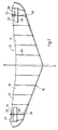
- the hang glider 10 has a right wing 12 and a left wing 14.
- the wings 12 and 14 are formed by a light, detachable frame 16 which is provided with a fabric covering 18.
- the frame has, in particular, reinforcing ribs 20, which are held in pockets of the fabric covering and extend approximately in the direction of flight.
- a trapezoid is arranged under the wings 12, 14.
- the trapezoid 22 is clamped to the frame 16 of the wings 12, 14 by stages 24, 26, 28, 30 and others, so that an essentially rigid structure is created. The pilot hangs in the trapeze 22.
- spoiler flaps 34 and 36 are now provided in the region of the wing ends.
- the spoiler flaps 34 and 36 can be actuated independently of one another.
- each of the spoiler flaps 34 and 36 can be pivoted into an active position against the action of a return spring 42 or 44 via an actuating cable 38 or 40.
- the spoiler flaps are essentially perpendicular to the surface of the wings and essentially perpendicular to the direction of flight .
- the spoiler flaps 34 and 36 are each attached to the surface of the wing 12 and 14 along a longitudinal side 46 and 48 running transversely to the direction of flight.
- the spoiler flaps 34 and 36 are each held in a rest position by one of the return springs 42 and 44, respectively, in which they rest flat on the surface of the wing 12 and 14, respectively.
- the actuating cable 38 or 40 engages in the region of the long side 50 or 52 of the spoiler flap 34 or 36 which is opposite the long side 46 or 48 fastened to the surface of the wing.
- the spoiler flaps 34 and 36 are designed to be resilient and flexible. This ensures that the spoiler flaps can nestle close to the surface of the wings 12 and 14 in the rest position under the influence of the return spring 42 and 44 and do not affect the aerodynamic conditions. You can be so too easy to handle when the hang glider is dismantled and needs to be packed to save space.
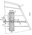
- the spoiler flaps have film or fabric parts 54. These film or fabric parts 54 form pockets, as will be described. Resiliently stiffening members are arranged in these pockets.
- the spoiler flaps 34 and 36 are each formed by two elongated, superimposed film or fabric parts 54 of a rectangular basic shape. Each spoiler flap is attached to the wing 12 and 14 of the hang glider along a longitudinal side 46 and 48, respectively.
- the film or fabric parts 54 of each spoiler flap 34 or 36 form a narrow pocket 56 in the middle thereof, which extends perpendicular to the longitudinal side 46 or 48 and across the width of the spoiler flap 34 or 36.
- the pocket 56 receives a reinforcing rib 58.
- Pockets 60, 62, 64 and 66 which extend in the longitudinal direction of the spoiler flaps 34 and 36 are formed on both sides of the reinforcing rib 58 and accommodate foam strips 68.
- foam instead of foam, another material that is elastically flexible can also be used.
- a pocket 70 extends along the entire long side 50 or 52 of the spoiler flap 34 or 36. This long side 50 or 52 lies opposite the long side 46 or 48, along which the spoiler flap 34 or 36 on the wing 12 or 14 is attached.
- This pocket 70 there is a reinforcing rib 72 which extends over the entire length of the spoiler flap 34 or 36.
- An arm 74 projecting from the spoiler surface is connected to said reinforcing rib 72.
- the arm 74 which is designed as a tension spring, engages on one side Return spring 42 or 44 and on the other side the actuating cable 38 or 40 on.
- the return spring is designed as an elastic band.
- the actuating cable 38.40 is expediently a Bowden cable.
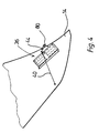
- the spoiler flap 36 is attached to the wing 14 in the region of a reinforcing rib 76 approximately symmetrically and transversely to the latter.
- the reinforcement rib 76 sits - similar to the other reinforcement ribs 20 of the frame 16 in a pocket 78 of the fabric forming the wing 14 and protrudes from this pocket 78 with a fork-shaped end 80.
- the reinforcing rib 76 is held in the pocket 78 by a spring tension or elastic band 82. This spring tension is held on both sides of the reinforcing rib 76 in eyelets 84, 86 which are attached in the fabric.
- the return spring 44 for the spoiler flap 36 is attached on the one hand to the fork-shaped end of the reinforcing rib 76 and on the other hand to the said arm 74 on the spoiler flap.
- the pocket 70 with the reinforcing rib 72 is first folded out of the surface of the wing 14. This initially "extends” a small flap area.
- the actuating cable 40 is actuated further, the remaining area of the spoiler flap 36 is then pivoted upward.
- each spoiler flap 34 or 36 is initially guided within the wing 12 or 14 and then runs along a stay 26 or 28 to the trapeze 22. There is each actuating cable 38 and 40 with a sleeve 88 or 90 connected. The sleeves 88, 90 are slidably guided on the cross strut 32 of the trapezoid of the hang glider 10. The spoiler flaps 34, 36 can thus be conveniently operated by the pilot.
Landscapes
- Engineering & Computer Science (AREA)
- Aviation & Aerospace Engineering (AREA)
- Supports Or Holders For Household Use (AREA)
- Holders For Apparel And Elements Relating To Apparel (AREA)
- Superstructure Of Vehicle (AREA)
- Toys (AREA)
Claims (8)
- Dispositif de commande pour des planeurs pendants, dans lequel dans la zone des extrémités d'aile du planeur pendant (10), des abattants (34, 36) sont montés sur l'aile (12,14) de sorte à pouvoir pivoter respectivement le long du grand côté avant de l'abattant (46,48) s'étendant transversalement à la direction de vol, et sont pivotables par un vérin (38,40) agissant sur le grand côté arrière de l'abattant (34,36),
caractérisé par le fait que(a) les abattants (34,36) sont montés sur la surface des ailes (12,14),(b) les abattants sont élastiquement fexibles, et(c) les abattants sont tenu par un ressort de rappel (42,44) à la fois dans une position d'arrêt dans laquelle ils sont couchés planement sur la surface de l'aile (12,14). - Dispositif de commande selon la revendication 1, caractérisé par le fait que les abattants (34,36) sont actionnables indépendemment l'un de l'autre.
- Dispositif de commande selon la revendication 1, caratérisé par le fait que(a) les abattants déporteurs (34,36) présentent des éléments de feuille ou de tissu (54),(b) ces éléments de feuille ou de tissu (54) forment des poches, et(c) des éléments de renforcement élastiquement flexibles sont disposés dans ces poches.
- Dispositif de commande selon la revendication 3, caractérise par le fait que(a) les abattants déporteurs (34,36) sont respectivement formés par deux éléments de feuille ou de tissu allongés généralement réctangulaires (54) disposés l'un sur l'autre,(b) chaque abattant déporteur (34,36) est fixé le long d'un grand côté d'abattant (46,48) sur l'ail (12,14) du planeur pendant (10),(c) une poche étroite s'étendant perpendiculairement audit grand côté d'abattant (46,48) sur la largeur de l'abattant déporteur (34,36) et recevant une nervure de renforcement (58) est formée au centre par les éléments de feuille ou de tissu (54) de chaque abattant déporteur,(d) des poches (60,62,64,66) sont formées, qui s'étendent des deux côtés de ladite nervure de renforcement (58) dans la direction longitudinale de l'abattant déporteur et qui recoivent des barres de produit alvéolaire (68).
- Dispositif de commande selon la revendication 4, caractérisé par le fait que(a) une poche (70) est formée le long du grand côté (50,52) de l'abattant déporteur (34,36), qui est en face du grand côté (46,48) le long duquel l'abattant déporteur (34,36) est fixé à l'aile (12,14),(b) une nervure de renforcement (72) s'étendant sur toute la longueur de l'abattant déporteur (34,36) est disposée dans cette poche (70).
- Dispositif de commande selon la revendication 5, caractérisé par le fait que(a) un bras (74) saillant de la surface de déporteur est relié à ladite nervure de renforcement (72), et(b) le ressort de rappel (42,44) formé comme ressort de tension agit sur le bras (74) vers un côté et le vérin (38,40) agit sur le bras (74) vers l'autre côté.
- Dispositif de commande selon la revendication 6, caractérisé par le fait que(a) l'abattant départeur (34,36) est monté sur l'aile (12,14) dans la zone d'une nervure de renforcement (76) approximativement symmétriquement et transversalement à celle-ci,(b) la nervure de renforcement (76) est située dans une poche (78) du tissu formant l'aile (12,14) et saillant bars de cette poche avec une extrémité bifurquée (80), la nervure de renforcement (76) étant tenue dans des oeillets (84,86) prévus dans le tissu,(c) le ressort de rappel (44) pour l'abattant départeur (34,36) est suspendu sur un côté à l'extrémité bifurquée (80) de la nervure de renforcement (76) et sur l'autre côté audit bras (74) à l'abattant déporteur (34,36).
- Dispositif de commande selon la revendication 7, caractérisé par le fait que le vérin (38,40) de chaque abattant déporteur (34,36) est relié à un manchon (88,90) guidé de sorte à pouvoir être déplacé sur le renforcement diagonal (32) du trapèze du planeur pendant (10).
Priority Applications (1)
| Application Number | Priority Date | Filing Date | Title |
|---|---|---|---|
| AT87902039T ATE72642T1 (de) | 1987-03-03 | 1987-03-03 | Steuervorrichtung fuer haengegleiter. |
Applications Claiming Priority (1)
| Application Number | Priority Date | Filing Date | Title |
|---|---|---|---|
| PCT/DE1987/000089 WO1988006550A1 (fr) | 1987-03-03 | 1987-03-03 | Dispositif de direction d'ailes-delta |
Publications (2)
| Publication Number | Publication Date |
|---|---|
| EP0346323A1 EP0346323A1 (fr) | 1989-12-20 |
| EP0346323B1 true EP0346323B1 (fr) | 1992-02-19 |
Family
ID=6803273
Family Applications (1)
| Application Number | Title | Priority Date | Filing Date |
|---|---|---|---|
| EP87902039A Expired - Lifetime EP0346323B1 (fr) | 1987-03-03 | 1987-03-03 | Dispositif de direction d'ailes-delta |
Country Status (4)
| Country | Link |
|---|---|
| EP (1) | EP0346323B1 (fr) |
| AT (1) | ATE72642T1 (fr) |
| DE (1) | DE3776804D1 (fr) |
| WO (1) | WO1988006550A1 (fr) |
Families Citing this family (3)
| Publication number | Priority date | Publication date | Assignee | Title |
|---|---|---|---|---|
| FR2669297A1 (fr) * | 1990-11-21 | 1992-05-22 | Pradel Andre | Dispositif de pilotage par manche d'un ulm pendulaire a l'interieur d'un carenage integral. |
| AT406664B (de) * | 1998-11-20 | 2000-07-25 | Villinger Markus | Fluggerät |
| AT406859B (de) | 1998-11-20 | 2000-10-25 | Villinger Markus | Fluggerät |
Family Cites Families (2)
| Publication number | Priority date | Publication date | Assignee | Title |
|---|---|---|---|---|
| FR1449983A (fr) * | 1965-09-24 | 1966-05-06 | Ryan Aeronautical Co | Avion à aile flexible à empennage intégré |
| FR2535285A1 (fr) * | 1982-10-29 | 1984-05-04 | Sellenet Pierre | Dispositif de couplage d'un ancrage flottant a des gouvernes aerodynamiques sur les planeurs ultra-legers |
-
1987
- 1987-03-03 AT AT87902039T patent/ATE72642T1/de not_active IP Right Cessation
- 1987-03-03 DE DE8787902039T patent/DE3776804D1/de not_active Expired - Lifetime
- 1987-03-03 WO PCT/DE1987/000089 patent/WO1988006550A1/fr not_active Ceased
- 1987-03-03 EP EP87902039A patent/EP0346323B1/fr not_active Expired - Lifetime
Also Published As
| Publication number | Publication date |
|---|---|
| ATE72642T1 (de) | 1992-03-15 |
| EP0346323A1 (fr) | 1989-12-20 |
| DE3776804D1 (de) | 1992-03-26 |
| WO1988006550A1 (fr) | 1988-09-07 |
Similar Documents
| Publication | Publication Date | Title |
|---|---|---|
| DE68913302T2 (de) | Drachenartiges fluggerät mit zwei griffen und vierpunktsteuerung. | |
| DE2737597A1 (de) | Fluggeraet | |
| DE2530210A1 (de) | Freifluegel | |
| WO2019034765A1 (fr) | Aéronef à décollage vertical | |
| EP0076954A1 (fr) | Voile tenue par la main | |
| EP0346323B1 (fr) | Dispositif de direction d'ailes-delta | |
| DE1801789A1 (de) | Flugzeug,insbesondere Segelflugzeug | |
| EP0127652B1 (fr) | Structure d'avion pour decollage et atterrissage sur les pieds du pilote | |
| DE1948934A1 (de) | Fallschirm | |
| DE1506068A1 (de) | Lenkbarer Gleitfallschirm | |
| DE602004005602T2 (de) | Starrer flügel mit variablem auftrieb aufgrund des ausklappens eines flexiblen flügels | |
| DE4010877A1 (de) | Staufluegelboot | |
| DE102022124533A1 (de) | Tragflügel oder Höhenleitwerk für ein Flugobjekt | |
| DE2549393A1 (de) | Deltagleiter | |
| DE602005000123T2 (de) | Verfahren zur Sicherung eines horizontal mit Niedriggeschwindigkeit fliegenden Flugzeuges | |
| DE662729C (de) | Vorrichtung zur Erhoehung des Auftriebs von Flugzeugtragfluegeln | |
| DE102017128164B4 (de) | Flugzeug | |
| DE2803041A1 (de) | Schwanzloses flugzeug | |
| DE1952204A1 (de) | Gleitregeleinrichtung fuer Fallschirme mit regelbarer Sinkgeschwindigkeit | |
| DE677527C (de) | Tragflaeche fuer Flugzeuge | |
| EP0563909A1 (fr) | Véhicule à effet de sol | |
| EP0188998A1 (fr) | Avion à haute manoeuvrabilité | |
| DE3516998C2 (fr) | ||
| DE960872C (de) | Flugzeug mit feststehenden Fluegeln grossen Auftriebsbeiwertes | |
| DE102017122359A1 (de) | Luftfahrzeug in Drachenkonfiguration |
Legal Events
| Date | Code | Title | Description |
|---|---|---|---|
| PUAI | Public reference made under article 153(3) epc to a published international application that has entered the european phase |
Free format text: ORIGINAL CODE: 0009012 |
|
| 17P | Request for examination filed |
Effective date: 19890831 |
|
| AK | Designated contracting states |
Kind code of ref document: A1 Designated state(s): AT CH DE FR GB IT LI |
|
| 17Q | First examination report despatched |
Effective date: 19910417 |
|
| GRAA | (expected) grant |
Free format text: ORIGINAL CODE: 0009210 |
|
| AK | Designated contracting states |
Kind code of ref document: B1 Designated state(s): AT CH DE FR GB IT LI |
|
| PG25 | Lapsed in a contracting state [announced via postgrant information from national office to epo] |
Ref country code: GB Effective date: 19920219 Ref country code: IT Free format text: LAPSE BECAUSE OF FAILURE TO SUBMIT A TRANSLATION OF THE DESCRIPTION OR TO PAY THE FEE WITHIN THE PRESCRIBED TIME-LIMIT;WARNING: LAPSES OF ITALIAN PATENTS WITH EFFECTIVE DATE BEFORE 2007 MAY HAVE OCCURRED AT ANY TIME BEFORE 2007. THE CORRECT EFFECTIVE DATE MAY BE DIFFERENT FROM THE ONE RECORDED. Effective date: 19920219 Ref country code: FR Effective date: 19920219 |
|
| REF | Corresponds to: |
Ref document number: 72642 Country of ref document: AT Date of ref document: 19920315 Kind code of ref document: T |
|
| PGFP | Annual fee paid to national office [announced via postgrant information from national office to epo] |
Ref country code: AT Payment date: 19920313 Year of fee payment: 6 |
|
| REF | Corresponds to: |
Ref document number: 3776804 Country of ref document: DE Date of ref document: 19920326 |
|
| PG25 | Lapsed in a contracting state [announced via postgrant information from national office to epo] |
Ref country code: CH Effective date: 19920331 Ref country code: LI Effective date: 19920331 |
|
| EN | Fr: translation not filed | ||
| GBV | Gb: ep patent (uk) treated as always having been void in accordance with gb section 77(7)/1977 [no translation filed] | ||
| REG | Reference to a national code |
Ref country code: CH Ref legal event code: PL |
|
| PLBE | No opposition filed within time limit |
Free format text: ORIGINAL CODE: 0009261 |
|
| STAA | Information on the status of an ep patent application or granted ep patent |
Free format text: STATUS: NO OPPOSITION FILED WITHIN TIME LIMIT |
|
| 26N | No opposition filed | ||
| PG25 | Lapsed in a contracting state [announced via postgrant information from national office to epo] |
Ref country code: AT Effective date: 19930303 |
|
| PGFP | Annual fee paid to national office [announced via postgrant information from national office to epo] |
Ref country code: DE Payment date: 19930927 Year of fee payment: 7 |
|
| PG25 | Lapsed in a contracting state [announced via postgrant information from national office to epo] |
Ref country code: DE Effective date: 19941201 |