EP0346231B1 - Bohrmaschine, insbesondere für programmierbare Maschine - Google Patents
Bohrmaschine, insbesondere für programmierbare Maschine Download PDFInfo
- Publication number
- EP0346231B1 EP0346231B1 EP19890401589 EP89401589A EP0346231B1 EP 0346231 B1 EP0346231 B1 EP 0346231B1 EP 19890401589 EP19890401589 EP 19890401589 EP 89401589 A EP89401589 A EP 89401589A EP 0346231 B1 EP0346231 B1 EP 0346231B1
- Authority
- EP
- European Patent Office
- Prior art keywords
- drill
- nose
- tool
- axis
- drilling
- Prior art date
- Legal status (The legal status is an assumption and is not a legal conclusion. Google has not performed a legal analysis and makes no representation as to the accuracy of the status listed.)
- Expired - Lifetime
Links
- 238000005553 drilling Methods 0.000 claims description 44
- 230000003100 immobilizing effect Effects 0.000 claims description 3
- 210000001331 nose Anatomy 0.000 description 47
- 238000003032 molecular docking Methods 0.000 description 42
- 238000003801 milling Methods 0.000 description 11
- 230000006835 compression Effects 0.000 description 8
- 238000007906 compression Methods 0.000 description 8
- 238000007747 plating Methods 0.000 description 6
- 230000000694 effects Effects 0.000 description 5
- 230000000295 complement effect Effects 0.000 description 3
- 239000012530 fluid Substances 0.000 description 3
- 210000000887 face Anatomy 0.000 description 2
- 230000005484 gravity Effects 0.000 description 2
- 230000000977 initiatory effect Effects 0.000 description 2
- 238000003754 machining Methods 0.000 description 2
- 239000000463 material Substances 0.000 description 2
- 239000000565 sealant Substances 0.000 description 2
- 230000015572 biosynthetic process Effects 0.000 description 1
- 230000000903 blocking effect Effects 0.000 description 1
- 230000001609 comparable effect Effects 0.000 description 1
- 230000007797 corrosion Effects 0.000 description 1
- 238000005260 corrosion Methods 0.000 description 1
- 238000001514 detection method Methods 0.000 description 1
- 238000006073 displacement reaction Methods 0.000 description 1
- 239000013536 elastomeric material Substances 0.000 description 1
- 238000009434 installation Methods 0.000 description 1
- 238000005461 lubrication Methods 0.000 description 1
- 239000013521 mastic Substances 0.000 description 1
- 230000036316 preload Effects 0.000 description 1
- 238000005096 rolling process Methods 0.000 description 1
- 238000000926 separation method Methods 0.000 description 1
Images


Classifications
-
- B—PERFORMING OPERATIONS; TRANSPORTING
- B23—MACHINE TOOLS; METAL-WORKING NOT OTHERWISE PROVIDED FOR
- B23Q—DETAILS, COMPONENTS, OR ACCESSORIES FOR MACHINE TOOLS, e.g. ARRANGEMENTS FOR COPYING OR CONTROLLING; MACHINE TOOLS IN GENERAL CHARACTERISED BY THE CONSTRUCTION OF PARTICULAR DETAILS OR COMPONENTS; COMBINATIONS OR ASSOCIATIONS OF METAL-WORKING MACHINES, NOT DIRECTED TO A PARTICULAR RESULT
- B23Q3/00—Devices holding, supporting, or positioning work or tools, of a kind normally removable from the machine
- B23Q3/002—Means to press a workpiece against a guide
-
- B—PERFORMING OPERATIONS; TRANSPORTING
- B23—MACHINE TOOLS; METAL-WORKING NOT OTHERWISE PROVIDED FOR
- B23B—TURNING; BORING
- B23B31/00—Chucks; Expansion mandrels; Adaptations thereof for remote control
- B23B31/02—Chucks
- B23B31/10—Chucks characterised by the retaining or gripping devices or their immediate operating means
- B23B31/107—Retention by laterally-acting detents, e.g. pins, screws, wedges; Retention by loose elements, e.g. balls
- B23B31/1071—Retention by balls
-
- B—PERFORMING OPERATIONS; TRANSPORTING
- B23—MACHINE TOOLS; METAL-WORKING NOT OTHERWISE PROVIDED FOR
- B23B—TURNING; BORING
- B23B49/00—Measuring or gauging equipment on boring machines for positioning or guiding the drill; Devices for indicating failure of drills during boring; Centering devices for holes to be bored
- B23B49/003—Stops attached to drilling tools, tool holders or drilling machines
- B23B49/006—Attached to drilling machines
- B23B49/008—Attached to the nose of the drilling machines
-
- B—PERFORMING OPERATIONS; TRANSPORTING
- B23—MACHINE TOOLS; METAL-WORKING NOT OTHERWISE PROVIDED FOR
- B23Q—DETAILS, COMPONENTS, OR ACCESSORIES FOR MACHINE TOOLS, e.g. ARRANGEMENTS FOR COPYING OR CONTROLLING; MACHINE TOOLS IN GENERAL CHARACTERISED BY THE CONSTRUCTION OF PARTICULAR DETAILS OR COMPONENTS; COMBINATIONS OR ASSOCIATIONS OF METAL-WORKING MACHINES, NOT DIRECTED TO A PARTICULAR RESULT
- B23Q16/00—Equipment for precise positioning of tool or work into particular locations not otherwise provided for
-
- B—PERFORMING OPERATIONS; TRANSPORTING
- B23—MACHINE TOOLS; METAL-WORKING NOT OTHERWISE PROVIDED FOR
- B23Q—DETAILS, COMPONENTS, OR ACCESSORIES FOR MACHINE TOOLS, e.g. ARRANGEMENTS FOR COPYING OR CONTROLLING; MACHINE TOOLS IN GENERAL CHARACTERISED BY THE CONSTRUCTION OF PARTICULAR DETAILS OR COMPONENTS; COMBINATIONS OR ASSOCIATIONS OF METAL-WORKING MACHINES, NOT DIRECTED TO A PARTICULAR RESULT
- B23Q17/00—Arrangements for observing, indicating or measuring on machine tools
- B23Q17/22—Arrangements for observing, indicating or measuring on machine tools for indicating or measuring existing or desired position of tool or work
- B23Q17/2216—Arrangements for observing, indicating or measuring on machine tools for indicating or measuring existing or desired position of tool or work for adjusting the tool into its holder
- B23Q17/2225—Arrangements for observing, indicating or measuring on machine tools for indicating or measuring existing or desired position of tool or work for adjusting the tool into its holder with the toolholder as reference-element
Definitions
- the invention relates to a drill designed in particular for use on a programmable machine such as a robot.
- a telescopic nose is mounted on the body of a drill, around of the spindle and the tool, so as to come to bear on the part before the start of drilling and to be pressed against this part by a compression spring.
- This telescopic nose has the function of ensuring the lubrication of the tool flush with the surface of the part and of sucking the chips.
- the invention mainly relates to a drill usable in particular on a programmable machine and whose particular structure allows it to guarantee the application of a predetermined clamping force on the parts around the drill, before the start of drilling, without the '' footprint of the drill is seriously increased, and also to control the automatic initiation of the drilling cycle of the drill.
- a drill comprising a body in which a tool-holder spindle is rotatably mounted around a drilling axis, and sliding along this axis, the body of the drill supporting a docking nose capable of slide along said axis, against an elastic means, when this docking nose comes to bear on a part to be drilled, so that the elastic means then exerts a pressing force on the part, by the intermediate of the docking nose, the drill being characterized by the fact that it further comprises a reversing detector of the docking nose, capable of triggering a drilling cycle during a determined sliding of the docking nose at the 'against said elastic means.
- the docking nose comprises a rotary end-of-travel stop on which a shoulder formed on the tool-holder spindle can come to bear.
- This characteristic allows precise control of the drilling depth, which is particularly advantageous when the drilling is accompanied by milling, as is particularly the case when the parts are assembled using blind rivets. It should be noted that the completion of the end stop on a movable docking nose relative to the body of the drill makes it possible to guarantee the precision of the drilling or milling depth, despite the recoil of the body of the drill which tends to occur when the tool comes into contact with the workpiece.
- the docking nose is fixed to the body of the drill by a removable retaining ring having an internal shoulder against which is normally supported an external shoulder of the docking nose, under the action of said elastic means.
- This characteristic makes it possible to adapt docking noses on the same drill, the length and / or the shape of which may be different, to take account in particular of a change in thickness and / or in shape of the parts to be drilled. It also makes it possible to use elastic means making it possible to apply different plating forces, to adapt these forces to the nature and the thickness of the materials to be drilled.
- the reversing detector may in particular comprise a pneumatic circuit comprising a passage formed in the body of the drill and opening out of the latter, so as to be obstructed by the docking nose after said determined sliding.
- the drill When it is mounted on a programmable machine, it is advantageous that the drill is equipped with an automatic tool changer, especially when the parts to be assembled require successively drilling holes of different diameters.
- the presence of an automatic tool changer also allows drilling to continue in the event of drill bits breaking.
- this changer preferably includes a locking ring mounted on the tool-holder spindle so that it can slide along said axis, an elastic means interposed between the spindle and the locking ring to move the latter to a rear locking position, a jack housed in the body of the drill and a piston of which is able to move the locking ring to a position before unlocking when said actuator is actuated, and at least two balls housed in two passages passing radially through the tool-holder spindle, so as to protrude in two half-grooves formed on a frustoconical external surface of the tool, complementary to a frustoconical internal surface of the spindle, when the locking ring is in its rear locking position, and so as to be retracted in an internal groove of the locking ring, when the latter occupies its position before unlocking.
- the automatic tool changer thus produced allows a particularly rapid change of the tool and an axial positioning of this tool in the very precise spindle, which is essential when the docking nose has an end stop. stroke determining the depth of drilling or milling.
- each tool preferably comprises a chuck with a conical shank on which said frustoconical outer surface is formed, a drill bit supported on an adjustment screw screwed along the axis of the mandrel, and means for immobilizing the drill bit in said mandrel.
- This configuration allows, thanks to the adjusting screw, to adjust on a presetting bench provided for this purpose the axial positioning of the drill relative to the mandrel in which it is fixed.
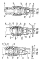
- the drill of which only the front part is shown in FIG. 1, is designed to be mounted on a programmable machine such as a robot which can have any shape (mobile carriage on a horizontal gantry also mobile, articulated arm, etc.).
- a programmable machine such as a robot which can have any shape (mobile carriage on a horizontal gantry also mobile, articulated arm, etc.).
- the drill comprises a body 10, intended to be fixed on the programmable machine, and a cylindrical spindle 12 mounted in the body 10 so as to be able to rotate around a vertical drilling axis in FIG. 1 and so to be able to move along this axis.
- Control means housed in the body 10 of the drill, make it possible to control the driving in rotation of the spindle 12 and the movement of this spindle along its axis, in one or the other direction.
- These control means known in themselves, are preferably mechanical when a regular advance of the tool is desired. Otherwise, they can also be pneumatic.
- the spindle 12 is hollow and has a frustoconical inner surface 12a into which a complementary frustoconical outer surface 14a can fit, formed on a mandrel with a conical shank 14 constituting a part of a drilling tool 16 which will be described in more detail later.
- the drill shown in Figure 1 is equipped with an automatic tool changer whose various components will now be described.
- This changer firstly comprises a locking ring 18 mounted around the end of the spindle 12, so as to be able to slide axially on the latter, while being integral with the latter in rotation, for example by means of pins (not shown) integral with the ring 18 and projecting radially in longitudinal grooves (not shown) formed on the cylindrical outer surface of the end of the spindle 12.
- a helical compression spring 20 is arranged around the ring 18 and is supported, by one of its ends, on a shoulder 12b formed at the end of the pin 12 and, by its opposite end, on a shoulder 18a formed on the ring 18.
- the shoulder 12b is constituted by a washer screwed to the end of the spindle 12.
- the spring 20 normally biases a shoulder 18b formed inside the ring 18 against a stop segment 22 mounted in a groove formed in the outer surface of the spindle 12. The position thus normally occupied by the ring 18 under the action of the compression spring 20 is called rear locking position.
- Means are provided in the passages in which the balls 24 are placed, in order to prevent them from escaping inside the spindle 12 when no tool is present.
- the automatic tool changer of the drill represented in FIG. 1 further comprises a single-acting cylinder housed in the body 10 of the drill. More specifically, the body of the drill constitutes the cylinder of this jack, in which an annular piston 26 is capable of sliding in leaktight manner.
- the annular piston 26 has a large diameter front part, which slides in leaktight manner inside the body 10 by means of an O-ring seal 28 received in a groove formed in the external surface of this front part. .
- the piston 26 also comprises a rear part of smaller diameter whose outer surface slides in a sealed manner inside the body 10 by means of another O-ring 30 received in a groove formed inside the body 10
- An annular chamber 32 is thus formed between the seals 28 and 30. This chamber 32 is connected by a pipe 34 to a pneumatic circuit for controlling the jack (not shown).
- a needle stop 36 held in abutment against a shoulder 26a formed in the piston, by a stop segment 38.
- the stop 36 is capable of coming to bear on the rear end of the ring 18. Consequently, when pressurized fluid is introduced through the pipe 34 into the chamber 32, the piston 26 moves forward inside the body 10 and also pushes the ring 18 forward against the action of the spring 20.
- the ring 18 can thus be brought into a position before unlocking determined by the abutment of the front face of the ring 18 against the shoulder 12b formed on the spindle 12.
- a groove 18c formed inside the ring 18 is located opposite the balls 24.
- the latter can therefore partially retract inside the groove 18c and, consequently, disengage from the half grooves 14b formed on the mandrel of the tool 16. The unlocking of the latter is thus achieved.
- the piston 26 is immobilized in rotation inside the body 10 of the drill by a screw 40 passing radially through the body 10 and the end of which projects into an axial slot 42 formed in the part rear of smaller diameter of the piston 26.
- This arrangement also makes it possible to limit the axial movement of the piston 26 inside the body of the drill by the abutment of the screw 40 on one or the other of the ends of the slot 42, in the direction of movement of the piston.
- the piston 26 is equipped internally at least one needle bearing 44 (two bearings 44 are provided in the embodiment shown). These bearings 44 are in rolling and sliding contact with the cylindrical outer surface of the spindle 12.
- the drill is also equipped with a docking nose 46 which is mounted at the end of the body 10 so as to be able to move relative to the latter parallel to the drilling axis .
- the docking nose 46 is fixed to the end of the body 10 of the drill so that it can be dismantled and replaced by a docking nose of different shape and / or dimensions.
- the body 10 in the zone surrounding the large diameter portion of the piston 26, the body 10 has a tubular protuberance 10a oriented towards the front of the drill and the outer surface of which is provided with a thread 10b.
- This thread 10b makes it possible to screw on the tubular protuberance 10a an outer ring 48 surrounding the front end of the body 10 while providing an annular space in which is housed a helical compression spring 50.
- the outer ring 48 has an inner shoulder 48a turned towards the rear and on which is normally supported an outer shoulder 46a, turned towards the front, formed at the rear end of the docking nose 46. Maintaining contact of the shoulders 46a and 48a is ensured by the compression spring 50, the ends of which bear respectively on the body 10, inside the tubular protuberance 10a, and on the rear end of the docking nose 46 .
- the end of the docking nose 46 can initially be brought into contact with the parts to be drilled, which has the effect of partially compressing the spring 50.
- the contact between the shoulders 46a and 48a is then eliminated, so that the prestress stored in the compression spring 50 is applied entirely to the docking nose 46 and transmitted to the parts to be drilled through the latter.
- the preload stored in the spring 50 therefore determines the plating force yes is applied to the parts when drilling is carried out.
- the front part 46b of the docking nose has a generally tubular shape whose diameter is as small as possible, so that the size of the nose does not prevent carrying out machining in places which are not easily accessible, for example in an angle.
- This tubular part 46b of the docking nose 46 is traversed by one or more openings 46c allowing the evacuation of the chips during drilling.
- the end face of this part 46b can be flat when the workpieces are themselves perfectly flat. As illustrated in FIG. 1, it can also include three or four projecting parts 46d regularly distributed over its circumference, so as to allow satisfactory support on a part of any shape.
- the recoil of the nose 46 which occurs when its front end comes into contact with the workpieces can be used to trigger the start of the drilling cycle of the drill, when the latter is automatic.
- the end part of the body 10 of the drill is equipped with an appropriate means making it possible to detect a predetermined displacement of the docking nose 46 against the compression spring 50.
- this detection means comprises a passage 54 formed in the body 10 of the drill and one end of which opens out through a leakage hole 57 in the annular space containing the spring 50, a predetermined distance behind the rear end of the docking nose 46, when the latter is pressed against the stop 48a by the spring 50.
- the opposite end of the passage 54 is connected by a pipe 56 to a pneumatic circuit (not shown) comprising a source of pressurized fluid which communicates with the passage 54 throughout the duration of the docking phase.
- This pipe 56 is also equipped with a leak sensor (not shown) which detects a predetermined pressure rise following the obstruction of the leak hole 56 by the rear end of the docking nose 46, after a predetermined retraction of this last. This leak sensor then automatically controls the stopping of the movement of the robot on which the drill is mounted and the start of the drilling cycle.
- the drill is also equipped with a stroke limiter making it possible to stop the advance of the spindle 12 of the drill when the drilling depth reaches a predetermined precise value.
- This characteristic is particularly advantageous when the drill 52 performs both drilling and milling, before the installation of an assembly rivet. Indeed, the depth of the milling constitutes a determining characteristic for a good resistance of the rivet.
- This stroke limiter comprises a needle stop 58 which is housed in the docking nose 46 immediately behind the front part 46b, pressing against a shoulder 46e precisely positioned relative to the end face of the docking nose, defined in the embodiment represented by the protrusions 46d.
- the needle bearing 58 is held against the shoulder 46e by a stop segment 60 housed in a groove formed for this purpose inside the docking nose 46.
- the length of the docking nose 46 as well as the positioning of the needle stop 58 inside this nose can vary.
- the removable nature of the docking nose makes it possible to replace it whenever necessary.
- a drill magazine is available for this purpose.
- This magazine has a fixed support 62 carrying a number of tool-holder pins 64, only one of which is shown in the figures.
- Each of these pins 64 projects radially beyond the surface of the support 62 and has a certain freedom of movement parallel to its axis.
- a compression spring 66 interposed between each of the pins 64 and the support 62 maintains normally the spindle in a rest position illustrated in Figure 2a, while allowing a certain retraction of this pin inside the support against the spring 66, as illustrated in Figure 2b.
- each of the tool-holder spindles 64 is pierced with a bore 64a in which the drill 52 of a tool 16 can be received.
- the spindles 64 being for example oriented vertically, the mandrel 14 of each of the tools 16 is then oriented upwards and the assembly rests by gravity in the corresponding bore 64a. If the spindles 64 are oriented differently, a suitable system such as a rod housed in the bore 64a makes it possible to maintain each chuck 14-tool 16 assembly on the corresponding spindle 64.
- the advance of the body 10 of the drill can continue until the frustoconical outer surface 14a of the chuck 14 of the tool is in contact with the frustoconical inner surface 12a of the spindle of the drill. As illustrated in FIG. 2b, a slight retraction of the spindle 64 is then allowed by the spring 66. The half-grooves 14b formed on the mandrel 14 are then located opposite the balls 24.
- the tool 16 is then gripped, so that the body 10 of the drill can move back by a reverse movement from the previous one, to go to make one or more holes using the tool 16.
- each drilling operation is broken down into an approach or docking phase and a drilling phase proper.
- pressurized fluid is injected through the pipe 56, as illustrated in FIG. 3a.
- the body 10 of the drill is then gradually moved towards the parts P to be drilled, which are placed on a support S.
- the motors controlling the rotation of the spindle 12 carrying the tool 16 as well as the regular advance of this spindle towards the parts P along the drilling axis are then actuated.
- the combined advance of the spindle 12 and of the tool 16 continues until the shoulder 12b comes to bear on the needle stop 58 placed inside the nose d docking 46. Since the distance separating the point of the drill 52 from the shoulder 12b can be determined with precision as will be seen below and that the distance separating the needle stop 58 from the end of the nose docking 46 is also determined with precision, the depth of drilling and milling carried out using the drill 52 is thus perfectly controlled. In particular, it is important to note that the depth obtained is completely independent of the precise position occupied by the body 10 of the drill relative to the parts P. Indeed, even if a recoil of the body 10 occurs during drilling as c is frequently the case, the end the nose 10 remains pressed against the parts P by the spring 50, so that the needle stop 58 remains perfectly positioned relative to the parts.
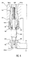
- each of the drilling tools 16 mounted on the drill 10 is designed so that it can be adjusted beforehand on a preset bench provided for this purpose.
- each of the tools 16 comprises, in addition to the taper shank chuck 14 and the drill 52, a screw 68 for axially positioning the drill 52 relative to the taper shank chuck 14, and means for immobilizing the drill by report to the mandrel.
- the screw 68 is screwed into a tapped hole passing along its axis the mandrel 14 and the end of this screw is supported on the rear face of the drill 52.
- the immobilization of the drill in the mandrel 14 is ensured by a conventional commercial collet chuck 70 surrounding the drill bit 52 and the frustoconical outer surface of which bears against a frustoconical inner surface 14c machined for this purpose in the chuck with conical shank 14.
- a ring 72 screwed onto the chuck 14 e taking pressing the collet chuck 70 ensures blocking.
- This bench consists of a fixed part 74 provided with a frustoconical recess 74a complementary to the external surface frustoconical 14a of the mandrel 14.
- the presetting bench further comprises an arm 76 able to move along the axis of the frustoconical recess 74a and in which is formed a bore 76a situated in the extension of this frustoconical recess.
- a socket 78 adapted to the drill 52 of the tool is placed in the bore 76a and the tool is placed in such a way that the frustoconical surface 14a of the mandrel is in abutment against the frustoconical surface 74a of the support 74 and that the drill 52 is in abutment in the socket 78.
- the ring 72 of the tool is then loosened in order to allow adjustment of the positioning of the point of the drill or of the part of the drill ensuring the milling, relative to the mandrel 14.
- the facing faces S1 and S2 respectively of the support 74 and of the socket 78 correspond on the bench to the front face of the shoulder 12b of the spindle 12 of the drill and to the surface of the part to be drilled.
- the ring 72 is screwed in order to immobilize the drill 52 in the chuck with conical shank 14. It should be noted that during drilling, the screw 68 constitutes a stop making it possible to avoid any retraction of the drill under the axial machining forces.
- the invention is not limited to the embodiment which has just been described by way of example.
- the tool changer and / or the stop determining the drilling depth can be omitted.
- the needle stops can be replaced by ball or roller stops.
- the pneumatic reversing sensor of the docking nose triggering the drilling cycle may be replaced by a detector of another type, such as an electrical contact.
- each spring 50 and 20 can be replaced by any other elastic means such as a stack of elastic washers.
Landscapes
- Engineering & Computer Science (AREA)
- Mechanical Engineering (AREA)
- Drilling And Boring (AREA)
- Drilling Tools (AREA)
- Automatic Tool Replacement In Machine Tools (AREA)
Claims (8)
- Bohrmaschine mit einem Körper (10), in dem eine Werkzeughalterspindel (12) drehbar um eine Bohrachse und gleitend entlang dieser Achse montiert ist, wobei der Körper (10) der Bohrmaschine eine Berührungssnase (46) trägt, die geeignet ist, entlang dieser Achse gegen eine elastische Vorrichtung (50) zu gleiten, wenn diese Berührungsnase sich auf ein zu bohrendes Teil stützt, so daß die elastische Vorrichtung dann über die Berührungsnase eine Druckwirkung auf das Teil ausübt, wobei die Bohrmaschine gekennzeichnet ist durch die Tatsache, daß sie außerdem einen Rückschrittdetektor (54, 56, 57) für die Berührungsnase (46) umfaßt, der geeignet ist, einen Bohrzyklus bei einem vorgegebenen Gleiten der Berührungsnase gegen die elastische Vorrichtung (50) auszulösen.
- Bohrmaschine nach Anspruch 1, gekennzeichnet durch die Tatsache, daß der Rückschrittdetektor einen pneumatischen Schaltkreis umfaßt, der einen Durchgang (54) umfaßt, der in dem Körper (10) der Bohrmaschine gearbeitet ist und derart in das Äußere des letzteren mündet, daß er von der Berührungsnase (46) nach dem vorgegebenen Gleiten blockiert wird.
- Bohrmaschine nach einem der Ansprüche 1 und 2, gekennzeichnet durch die Tatsache, daß sie einen automatischen Werkzeugwechsler umfaßt, der einen Verriegelungsring (18), der auf der Werkzeughalterspindel (12) derart montiert ist, daß er entlang der Achse gleiten kann, eine elastische Vorrichtung (20), die zwischen der Spindel und dem Verriegelungsring angeordnet ist, um letzteren in eine hintere Verschlußposition zu bewegen, eine in dem Körper der Bohrmaschine angeordnete Winde, von der ein Kolben (26) geeignet ist, bei eine Betätigung der Winde, den Verriegelungsring (18) in eine vordere Entriegelungsposition zu bewegen, und wenigstens zwei Kugeln (24) aufweist, die in zwei, die Werkzeughalterspindel radial durchquerende Durchgänge derart angeordnet sind, daß sie in zwei Halbeinschnitten (14b), die auf einer äußeren, kegelstumpfförmigen Oberfläche (14a) des Werkzeugs, die zu einer inneren, kegelstumpfförmigen Oberfläche (12a) der Spindel komplementär ist, vorstehen, wenn der Verriegelungsring in seiner hinteren Verschlußposition ist, und so, daß sie in einen inneren Einschnitt (18c) des Verriegelungsrings eingezogen werden, wenn letzterer seine vordere Entriegelungsposition einnimmt.
- Bohrmaschine nach Anspruch 3, gekennzeichnet durch die Tatsache, daß der Kolben (26) der Winde ein ringförmiger Kolben ist, der die Werkzeughalterspindel (12) in Drehung um die Bohrachse und in Translation entlang dieser Achse hält, wobei dieser Kolben sich auf den Verriegelungsring (18) stützt, der sich über einen drehenden Anschluß (36) mit der Werkzeugträgerspindel (12) dreht.
- Bohrmaschine nach einem der Ansprüche 3 und 4, gekennzeichnet durch die Tatsache, daß jedes Werkzeug (16) ein Futter mit einem kegelförmigen Ende (14), auf dem die äußere, kegelstumpfförmige Oberfläche (14a) geformt ist, wobei ein Bohrer (52) sich auf eine Regelungsschraube (68), die entlang der Achse des Futters geschraubt ist, stützt, und Vorrichtungen zum Unbeweglichmachen des Bohrers in dem Futter umfaßt.
- Bohrmaschine nach einem der Ansprüche 1 bis 5, gekennzeichnet durch die Tatsache, daß die Nase (46) einen rotierenden Anschlag (58) für das Wegende umfaßt, auf den sich eine auf der Werkzeughalterspindel (12) geformte Schulter (12a) stützen kann.
- Bohrmaschine nach Anspruch 6, gekennzeichnet durch die Tatsache, daß der rotierende Anschlag (58) gestützt gegen eine innere Schulter (46e), die in der Berührungsnase (46) durch ein Anhalteelement (60) gebildet wird, gehalten wird.
- Bohrmaschine nach einem der Ansprüche 1 bis 7, gekennzeichnet durch die Tatsache, daß die Berührungsnase (46) auf dem Körper (10) der Bohrmaschine durch einen demontierbaren Festhaltering (48) montiert ist, der eine innere Schulter (48a) aufweist, gegen die sich normalerweise eine äußere Schulter (46a) der Berührungsnase unter der Wirkung der elastischen Vorrichtung stützt.
Applications Claiming Priority (2)
| Application Number | Priority Date | Filing Date | Title |
|---|---|---|---|
| FR8807683 | 1988-06-09 | ||
| FR8807683A FR2632552B1 (fr) | 1988-06-09 | 1988-06-09 | Perceuse perfectionnee, notamment pour machine programmable |
Publications (2)
| Publication Number | Publication Date |
|---|---|
| EP0346231A1 EP0346231A1 (de) | 1989-12-13 |
| EP0346231B1 true EP0346231B1 (de) | 1992-09-23 |
Family
ID=9367106
Family Applications (1)
| Application Number | Title | Priority Date | Filing Date |
|---|---|---|---|
| EP19890401589 Expired - Lifetime EP0346231B1 (de) | 1988-06-09 | 1989-06-08 | Bohrmaschine, insbesondere für programmierbare Maschine |
Country Status (3)
| Country | Link |
|---|---|
| EP (1) | EP0346231B1 (de) |
| DE (1) | DE68902953T2 (de) |
| FR (1) | FR2632552B1 (de) |
Cited By (1)
| Publication number | Priority date | Publication date | Assignee | Title |
|---|---|---|---|---|
| FR3114985A1 (fr) * | 2020-10-12 | 2022-04-15 | Alex Grojean | Équipement, dispositif et procédé de démontage d’une pièce supérieure et d’une pièce inférieure assemblées par un insert soudé. |
Families Citing this family (13)
| Publication number | Priority date | Publication date | Assignee | Title |
|---|---|---|---|---|
| GB2319600B (en) * | 1996-11-22 | 1999-03-31 | British Aerospace | Machine tool attachment |
| US7073989B2 (en) * | 2003-03-31 | 2006-07-11 | The Boeing Company | Re-configurable bushing and drill incorporating same |
| DE102005061190B4 (de) | 2005-12-21 | 2007-10-18 | Airbus Deutschland Gmbh | Einrichtung zur Begrenzung des Vorschubes bei einem Bohrvorgang |
| US8348560B1 (en) | 2008-09-18 | 2013-01-08 | Variable Operations Technologies, Inc. | Tool head for a machine tool |
| DE102011102563B4 (de) | 2011-05-26 | 2014-10-09 | Kennametal Inc. | Werkzeugadapter mit einem Halter |
| US9061355B2 (en) | 2012-06-29 | 2015-06-23 | Kennametal Inc. | Tool adaptor having an integrated damping device |
| US9180529B1 (en) * | 2013-05-01 | 2015-11-10 | Christopher Harrison | Drilling system using a pocket hole joint method |
| CN103252519B (zh) * | 2013-05-02 | 2016-09-21 | 台州市盛业设备制造有限公司 | 两种孔径定位加工机构 |
| US9630258B2 (en) | 2014-10-15 | 2017-04-25 | Kennametal Inc | Tool holder assembly with dampening elements |
| DE102018206889A1 (de) * | 2018-05-04 | 2019-11-07 | Gühring KG | Zerspanungswerkzeug mit Tiefenanschlag |
| US20180272438A1 (en) * | 2018-05-25 | 2018-09-27 | Leroy K. Leo | Microstop Setting Station |
| CN111037300A (zh) * | 2019-12-30 | 2020-04-21 | 安徽瑞泰汽车零部件有限责任公司 | 一种用于汽车零部件加工的钻床 |
| AU2024286159A1 (en) * | 2023-06-09 | 2026-01-22 | Tech Products Co. | Depth setting bit drivers, systems and related methods |
Family Cites Families (6)
| Publication number | Priority date | Publication date | Assignee | Title |
|---|---|---|---|---|
| US2884819A (en) * | 1955-04-19 | 1959-05-05 | Wiesner Rapp Company Inc | Countersink machines |
| SE374288B (de) * | 1973-06-04 | 1975-03-03 | Eminentverktyg Ab | |
| DE2817218A1 (de) * | 1978-04-20 | 1979-10-31 | Trumpf Maschinen Ag | Werkzeugmaschine |
| JPS5859746A (ja) * | 1981-10-06 | 1983-04-08 | Sanshin Ind Co Ltd | 工作機械の集塵装置 |
| EP0193745B1 (de) * | 1985-03-06 | 1989-08-30 | International Business Machines Corporation | Druckfuss mit Kontaktpolster für eine Bohrmaschine |
| DE8605002U1 (de) * | 1986-02-25 | 1986-04-10 | Otto Bilz, Werkzeugfabrik Gmbh & Co, 7302 Ostfildern | Schnellwechselfutter für Werkzeuge |
-
1988
- 1988-06-09 FR FR8807683A patent/FR2632552B1/fr not_active Expired - Fee Related
-
1989
- 1989-06-08 EP EP19890401589 patent/EP0346231B1/de not_active Expired - Lifetime
- 1989-06-08 DE DE1989602953 patent/DE68902953T2/de not_active Expired - Fee Related
Cited By (1)
| Publication number | Priority date | Publication date | Assignee | Title |
|---|---|---|---|---|
| FR3114985A1 (fr) * | 2020-10-12 | 2022-04-15 | Alex Grojean | Équipement, dispositif et procédé de démontage d’une pièce supérieure et d’une pièce inférieure assemblées par un insert soudé. |
Also Published As
| Publication number | Publication date |
|---|---|
| FR2632552B1 (fr) | 1993-06-18 |
| EP0346231A1 (de) | 1989-12-13 |
| FR2632552A1 (fr) | 1989-12-15 |
| DE68902953D1 (de) | 1992-10-29 |
| DE68902953T2 (de) | 1993-03-25 |
Similar Documents
| Publication | Publication Date | Title |
|---|---|---|
| EP0346231B1 (de) | Bohrmaschine, insbesondere für programmierbare Maschine | |
| FR2481625A1 (fr) | Porte-outil a mecanisme correcteur de position d'outil | |
| EP0033908B1 (de) | Vorrichtung zum Drehantrieb eines zylindrischen Stückes | |
| EP0006806B1 (de) | Klemmeinrichtung für ein an beiden Enden gleichzeitig zu bearbeitendes Werkstück | |
| EP0373086A1 (de) | Montagevorrichtung für Kegelschäfte, insbesondere mit 7/24-Kegel für Anordnungen, Werkzeughalter und Werkzeuge | |
| EP0068952A1 (de) | Werkzeugmaschinen mit hoher Produktivität | |
| FR2937891A3 (fr) | Mandrin porte-foret auto-serrant | |
| FR3064511B1 (fr) | Mandrin de serrage a coulisseaux inclines | |
| WO2013010719A1 (fr) | Dispositif de maintien de pieces mecaniques | |
| EP3666432B1 (de) | Vorrichtung zur festen verbindung einer bohrvorrichtung mit einem bohrgitter, das einen kugelspannsatz umfasst | |
| EP0070208B1 (de) | Werkzeugmaschinen mit einem Drehkopf | |
| WO1981002543A1 (fr) | Mecanisme de presse hydraulique | |
| EP0179024B1 (de) | Montagevorrichtung für eine Spannzange zum Spannen eines Werkstückes in einer Werkzeugmaschine | |
| WO2016199047A1 (fr) | Tour d'usinage et canon de guidage | |
| FR2585278A1 (fr) | Procede pour la fixation rapide et precise de pieces a usiner a symetrie de revolution et dispositif de fixation rapide et precise pour la realisation du procede | |
| EP0090224A1 (de) | Spannvorrichtung eines Schneideneinsatzes auf einem Werkzeughalter | |
| FR2490518A1 (fr) | Mandrin expansible | |
| EP4084922B1 (de) | Elektrospindel mit integriertem vortrieb mit automatischem werkzeughalterwechsel | |
| FR2653363A1 (fr) | Ensemble d'usinage pour executer une multiplicite de trous dans une structure, telle que cellule d'avion, avec une grille munie de canons et au moins une machine de percage. | |
| FR2543866A1 (fr) | Dispositif de blocage et de deblocage automatiques d'un outil dans une broche rotative de machine-outil | |
| FR2848888A1 (fr) | Dispositif de fixation d'une tete de support d'au moins un outil a une broche d'une machine-outil | |
| EP0463433A1 (de) | Einstellbare Führungsbüchse für Drehautomat mit bewegendem Spindelstock | |
| FR2622489A1 (fr) | Mandrin de serrage, notamment pour des machines a avance automatique | |
| FR2673866A1 (fr) | Dispositif de decolletage d'ecrous. | |
| EP0085613A2 (de) | Spannvorrichtung für ein Werkstück |
Legal Events
| Date | Code | Title | Description |
|---|---|---|---|
| PUAI | Public reference made under article 153(3) epc to a published international application that has entered the european phase |
Free format text: ORIGINAL CODE: 0009012 |
|
| AK | Designated contracting states |
Kind code of ref document: A1 Designated state(s): CH DE GB LI NL |
|
| 17P | Request for examination filed |
Effective date: 19900518 |
|
| 17Q | First examination report despatched |
Effective date: 19910610 |
|
| GRAA | (expected) grant |
Free format text: ORIGINAL CODE: 0009210 |
|
| AK | Designated contracting states |
Kind code of ref document: B1 Designated state(s): CH DE GB LI NL |
|
| PG25 | Lapsed in a contracting state [announced via postgrant information from national office to epo] |
Ref country code: NL Effective date: 19920923 Ref country code: GB Effective date: 19920923 |
|
| REF | Corresponds to: |
Ref document number: 68902953 Country of ref document: DE Date of ref document: 19921029 |
|
| NLV1 | Nl: lapsed or annulled due to failure to fulfill the requirements of art. 29p and 29m of the patents act | ||
| GBV | Gb: ep patent (uk) treated as always having been void in accordance with gb section 77(7)/1977 [no translation filed] |
Effective date: 19920923 |
|
| PLBE | No opposition filed within time limit |
Free format text: ORIGINAL CODE: 0009261 |
|
| STAA | Information on the status of an ep patent application or granted ep patent |
Free format text: STATUS: NO OPPOSITION FILED WITHIN TIME LIMIT |
|
| 26N | No opposition filed | ||
| PGFP | Annual fee paid to national office [announced via postgrant information from national office to epo] |
Ref country code: DE Payment date: 20030627 Year of fee payment: 15 |
|
| PGFP | Annual fee paid to national office [announced via postgrant information from national office to epo] |
Ref country code: CH Payment date: 20030701 Year of fee payment: 15 |
|
| PG25 | Lapsed in a contracting state [announced via postgrant information from national office to epo] |
Ref country code: LI Free format text: LAPSE BECAUSE OF NON-PAYMENT OF DUE FEES Effective date: 20040630 Ref country code: CH Free format text: LAPSE BECAUSE OF NON-PAYMENT OF DUE FEES Effective date: 20040630 |
|
| PG25 | Lapsed in a contracting state [announced via postgrant information from national office to epo] |
Ref country code: DE Free format text: LAPSE BECAUSE OF NON-PAYMENT OF DUE FEES Effective date: 20050101 |
|
| REG | Reference to a national code |
Ref country code: CH Ref legal event code: PL |