EP0346146A2 - Appareil pour le déplacement des tables des machines pour le finissage de roues dentées - Google Patents
Appareil pour le déplacement des tables des machines pour le finissage de roues dentées Download PDFInfo
- Publication number
- EP0346146A2 EP0346146A2 EP89305868A EP89305868A EP0346146A2 EP 0346146 A2 EP0346146 A2 EP 0346146A2 EP 89305868 A EP89305868 A EP 89305868A EP 89305868 A EP89305868 A EP 89305868A EP 0346146 A2 EP0346146 A2 EP 0346146A2
- Authority
- EP
- European Patent Office
- Prior art keywords
- horizontal
- traversing
- guide member
- guide
- tables
- Prior art date
- Legal status (The legal status is an assumption and is not a legal conclusion. Google has not performed a legal analysis and makes no representation as to the accuracy of the status listed.)
- Withdrawn
Links
Images


Classifications
-
- B—PERFORMING OPERATIONS; TRANSPORTING
- B23—MACHINE TOOLS; METAL-WORKING NOT OTHERWISE PROVIDED FOR
- B23F—MAKING GEARS OR TOOTHED RACKS
- B23F23/00—Accessories or equipment combined with or arranged in, or specially designed to form part of, gear-cutting machines
- B23F23/12—Other devices, e.g. tool holders; Checking devices for controlling workpieces in machines for manufacturing gear teeth
- B23F23/1293—Workpiece heads
-
- B—PERFORMING OPERATIONS; TRANSPORTING
- B23—MACHINE TOOLS; METAL-WORKING NOT OTHERWISE PROVIDED FOR
- B23F—MAKING GEARS OR TOOTHED RACKS
- B23F19/00—Finishing gear teeth by other tools than those used for manufacturing gear teeth
- B23F19/06—Shaving the faces of gear teeth
-
- B—PERFORMING OPERATIONS; TRANSPORTING
- B23—MACHINE TOOLS; METAL-WORKING NOT OTHERWISE PROVIDED FOR
- B23Q—DETAILS, COMPONENTS, OR ACCESSORIES FOR MACHINE TOOLS, e.g. ARRANGEMENTS FOR COPYING OR CONTROLLING; MACHINE TOOLS IN GENERAL CHARACTERISED BY THE CONSTRUCTION OF PARTICULAR DETAILS OR COMPONENTS; COMBINATIONS OR ASSOCIATIONS OF METAL-WORKING MACHINES, NOT DIRECTED TO A PARTICULAR RESULT
- B23Q1/00—Members which are comprised in the general build-up of a form of machine, particularly relatively large fixed members
- B23Q1/25—Movable or adjustable work or tool supports
- B23Q1/44—Movable or adjustable work or tool supports using particular mechanisms
- B23Q1/48—Movable or adjustable work or tool supports using particular mechanisms with sliding pairs and rotating pairs
- B23Q1/4804—Movable or adjustable work or tool supports using particular mechanisms with sliding pairs and rotating pairs a single rotating pair followed perpendicularly by a single sliding pair
- B23Q1/4809—Movable or adjustable work or tool supports using particular mechanisms with sliding pairs and rotating pairs a single rotating pair followed perpendicularly by a single sliding pair followed perpendicularly by a single rotating pair
-
- B—PERFORMING OPERATIONS; TRANSPORTING
- B23—MACHINE TOOLS; METAL-WORKING NOT OTHERWISE PROVIDED FOR
- B23Q—DETAILS, COMPONENTS, OR ACCESSORIES FOR MACHINE TOOLS, e.g. ARRANGEMENTS FOR COPYING OR CONTROLLING; MACHINE TOOLS IN GENERAL CHARACTERISED BY THE CONSTRUCTION OF PARTICULAR DETAILS OR COMPONENTS; COMBINATIONS OR ASSOCIATIONS OF METAL-WORKING MACHINES, NOT DIRECTED TO A PARTICULAR RESULT
- B23Q1/00—Members which are comprised in the general build-up of a form of machine, particularly relatively large fixed members
- B23Q1/25—Movable or adjustable work or tool supports
- B23Q1/44—Movable or adjustable work or tool supports using particular mechanisms
- B23Q1/56—Movable or adjustable work or tool supports using particular mechanisms with sliding pairs only, the sliding pairs being the first two elements of the mechanism
- B23Q1/60—Movable or adjustable work or tool supports using particular mechanisms with sliding pairs only, the sliding pairs being the first two elements of the mechanism two sliding pairs only, the sliding pairs being the first two elements of the mechanism
- B23Q1/62—Movable or adjustable work or tool supports using particular mechanisms with sliding pairs only, the sliding pairs being the first two elements of the mechanism two sliding pairs only, the sliding pairs being the first two elements of the mechanism with perpendicular axes, e.g. cross-slides
- B23Q1/621—Movable or adjustable work or tool supports using particular mechanisms with sliding pairs only, the sliding pairs being the first two elements of the mechanism two sliding pairs only, the sliding pairs being the first two elements of the mechanism with perpendicular axes, e.g. cross-slides a single sliding pair followed perpendicularly by a single sliding pair
-
- Y—GENERAL TAGGING OF NEW TECHNOLOGICAL DEVELOPMENTS; GENERAL TAGGING OF CROSS-SECTIONAL TECHNOLOGIES SPANNING OVER SEVERAL SECTIONS OF THE IPC; TECHNICAL SUBJECTS COVERED BY FORMER USPC CROSS-REFERENCE ART COLLECTIONS [XRACs] AND DIGESTS
- Y10—TECHNICAL SUBJECTS COVERED BY FORMER USPC
- Y10T—TECHNICAL SUBJECTS COVERED BY FORMER US CLASSIFICATION
- Y10T409/00—Gear cutting, milling, or planing
- Y10T409/10—Gear cutting
- Y10T409/101431—Gear tooth shape generating
- Y10T409/105883—Using rotary cutter
- Y10T409/10636—On reciprocating carriage
-
- Y—GENERAL TAGGING OF NEW TECHNOLOGICAL DEVELOPMENTS; GENERAL TAGGING OF CROSS-SECTIONAL TECHNOLOGIES SPANNING OVER SEVERAL SECTIONS OF THE IPC; TECHNICAL SUBJECTS COVERED BY FORMER USPC CROSS-REFERENCE ART COLLECTIONS [XRACs] AND DIGESTS
- Y10—TECHNICAL SUBJECTS COVERED BY FORMER USPC
- Y10T—TECHNICAL SUBJECTS COVERED BY FORMER US CLASSIFICATION
- Y10T409/00—Gear cutting, milling, or planing
- Y10T409/30—Milling
- Y10T409/30868—Work support
-
- Y—GENERAL TAGGING OF NEW TECHNOLOGICAL DEVELOPMENTS; GENERAL TAGGING OF CROSS-SECTIONAL TECHNOLOGIES SPANNING OVER SEVERAL SECTIONS OF THE IPC; TECHNICAL SUBJECTS COVERED BY FORMER USPC CROSS-REFERENCE ART COLLECTIONS [XRACs] AND DIGESTS
- Y10—TECHNICAL SUBJECTS COVERED BY FORMER USPC
- Y10T—TECHNICAL SUBJECTS COVERED BY FORMER US CLASSIFICATION
- Y10T74/00—Machine element or mechanism
- Y10T74/18—Mechanical movements
- Y10T74/18568—Reciprocating or oscillating to or from alternating rotary
- Y10T74/18576—Reciprocating or oscillating to or from alternating rotary including screw and nut
- Y10T74/18648—Carriage surrounding, guided by, and primarily supported by member other than screw [e.g., linear guide, etc.]
Definitions
- This invention relates to a table traversing apparatus for traversing horizontally a table of a machine tool such as a gear finishing machine, for example a gear shaving machine, during a gear finishing operation on a gear supported by the table.
- a machine tool such as a gear finishing machine, for example a gear shaving machine
- Such a rotatable table may be releasably clamped to the traversable table or to a knee portion of a gear cutting machine. Prior to a gear finishing operation, the table may be unclamped, rotated to the required angular position using a table rotating means and then re-clamped.
- this kind of table mechanism which permits a work table to slide diagonally by a combination of a traversable table and rotatable table, requires a parallel link mechanism to ensure that the rotatable table is parallel to the traversable table and to ensure that the whole table assembly is horizontal (see, for example, Japanese Patent Publication No. 27-5197). Because of the accuracy required, such a parallel link mechanism is quite expensive.
- a structure for elimating the parallel link mechanism could comprise a pair of traversing tables, mounted to traverse in perpendicular direction, the pair of sliding tables being driven to traverse at the same time under the control of numerical control (NC) apparatus so as to traverse the work table diagonally.
- NC numerical control
- this structure requires a pair of feed motors for driving the pair of traversing tables and two sets of feed mechanisms disposed between respective tables and motors so that such a structure can hardly be said to be less expensive than the conventional structure comprising a parallel link mechanism.
- the diagonal traversing movement of the work table is attained by driving two sliding tables independently the centre of the work table does not necessarily cross the central axis of the machine during such a diagonal sliding movement. Consequently, the accuracy of gear finishing is impaired.
- a primary object of the present invention is to provide a novel table traversing apparatus for gear finishing machines in which a pair of traversing tables is employed such that diagonal traversing is attained by a single feed motor and so as to eliminate the problems set forth above.
- the invention provides a table traversing apparatus comprising a first horizontal table mounted for traversing in a first horizontal direction, a second horizontal table mounted for traversing in a second horizontal direction, one of the tables being mounted for traversing on top of and relative to the other table, the two horizontal directions being transverse to each other, a horizontal guide member for guiding the upper table during horizontal traversing thereof, the guide member being angularly adjustable about a vertical axis, a releasable clamp for preventing rotation of the guide member when clamped, means for angularly adjusting the guide member when unclamped, and a feed motor for driving one of the tables to traverse.
- the table traversing apparatus comprises first and second traversing tables.
- the first table is mounted to traverse horizontally in a first horizontal direction which extends left and right across the machine
- the second table is mounted to traverse horizontally in a second horizontal direction which extends from front to rear of the machine.
- the first and second directions are perpendicular to each other.
- Either one of the first and second table is mounted to traverse horizontally on the top of the other table.
- a horizontal guide member is provided for guiding the upper table during horizontal traversing movement of the upper table.
- This guide member is supported for rotation about a vertical axis and may be clamped non-rotatably by a releasable clamp.
- the apparatus according to the present invention further comprises a rotating means for rotating the guide member while unclamped, and a feed motor for traversing one of the tables.
- the table traversing apparatus operates as follows:
- the upper table When one table is traversed by the feed motor with the guide member placed in an angular position in which it extends at an angle to the first horizontal direction, the upper table traverses parallel to the guide member. Both tables traverse along their respective perpendicular axes to achieve diagonal motion of the upper table.
- the table traversing apparatus may be manufactured at low cost. This is because one of the first and second tables horizontally traversable along perpendicular directions is mounted for its horizontal traverse on the other table and is guided along a diagonal direction by a separate horizontal guide member so that the whole table assembly remains horizontal. An expensive parallel link mechanism is not therefore required. In addition only one feed motor is required for the two sliding tables so that the need for a pair of feed motors and two sets of feed mechanisms as in the numerically controlled table mechanism referred to before is eliminated.
- Another advantage of the present invention resides in that the accuracy of gear finishing is assured notwithstanding the use of two traversing tables. This is because a workpiece centred on the table assembly is necessarily moved, even during diagonal sliding movement thereof, so as to pass the centre of the machine. A work gear supported centrally on the table assembly is therefore necessarily moved past the centre of a gear-finishing tool such as shaving cutter.
- a first embodiment of a gear finishing machine is shown in Figure 1 to 6.
- the whole machine as shown in Figures 5 and 6 is embodied as a gear shaving machine.
- Table mechanism which is supported by a knee 8 on a bed 7 comprises the second table 2, set forth before, which is guided by a pair of rails 9 on the knee 8 so as to be slidable forwards and rearwards of the machine, the first table 1, set forth before, which is guided by a pair of rails 10 on the second table 2 so as to be slidable leftwards and rightwards of the machine, and a work table 12 which is supported by the first table 1 for rocking movement relative thereto about a horizontal pivot shaft 11 extending forwards and rearwards of the machine.
- the work table 12 carries left and right stocks 13 and 14 for supporting a work gear W.
- To one side of the table mechanism is associated a crowning guide 15 operable to guide the work table 12 for rocking movement when crowning is applied to the work gear or the teeth thereof.
- Bed 7 has at a rear side thereof an integral upstanding column 16 which supports a vertically slidable cutter head 18.
- This cutter head 18 which is lifted and lowered by a motor 17 comprises a shaving cutter C, fixedly mounted on a tool spindle (not shown), which in turn is driven to rotate by a spindle-driving motor 19.
- the rails 9 and 10 are fixed respectively to the upper faces of the knee 8 and second table 2 and are fitted respectively in rail-receiving grooves 21a and 22a of leg members 21 and 22, which in turn are fixed respectively to the lower faces of the second table 2 and first table 1, so as to slidably receive the respective tables 2 and 1.
- a circular disk 23 having its center on the vertical center axis of machine is disposed on a central portion of the upper face of the knee 8.
- This disk 23 has a vertical support shaft 25, attached to the lower face to the disk at a center portion thereof using screws 24, which is received rotatably through a bearing means by a hollow cylindrical support member 26 fixedly secured to a top wall of the knee 8.
- the disk 23 is thus supported rotatably about the vertical center axis of machine.
- the horizontal guide member 3 set forth before is fashioned to a rail of a relatively small length having a longitudinal axis parallel to a diametrical line of the disk 23 and is fixedly secured to the disk 23 using a pair of threaded fasteners 27.
- the first table 1 supports at a central portion thereof a rotatable support shaft 28 through a bearing means 30.
- This support shaft 28 is prevented from getting-away by a nut 29 threadingly engaged to a threaded upper end portion 28a of the shaft and includes at its lower end an integral rectangular plate portion 28b.
- To the lower face of the plate portion 28b is fixedly secured using screws 32 a guide-receiving member 33 which is formed with a receiving groove 33a having an open lower end.
- the guide member 3 is fittingly received in the groove 33a for relative sliding movement between the members 3 and 33.
- a pair of plates 34 which sandwich an upper end portion of the guide-receiving member 33 are attached to the rectangular plate portion 28b using screws 35.
- the second table 2 includes a central bore having a relatively large diameter within which the guide member 3 and guide-receiving member 33 extend.
- LM linear motion guide
- a rail means called “LM rail” having guide faces for the balls is also available in the market and may be used as the guide member 3.
- the aforestated means 4 for rotating the guide member 3 comprises a worm gear 38, fixedly mounted on a lower end portion of the support shaft 25 of the disk 23, and a worm 39 meshing with the worm gear 38.
- the worm 39 is formed integrally on a control shaft 40 which extends through and is supported rotatably by a front cover 8a of the knee 8 and has a squared outer end 40a for fittingly engaging a hand tool.
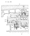
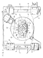
- the disk 23 is formed with a circular T-slot 41 at which the disk 23 is clamped non-rotatably by a clamp means 42, disposed within the knee 8, so as to fix the angular position of the guide member 3.
- a clamp means 42 disposed within the knee 8, so as to fix the angular position of the guide member 3.
- Three of such clamp means 42 are provided, as shown in FIG. 3, and each of these clamp means includes a clamp pin 43 shown in FIG. 2A having a clamping head 43a which is disposed within the T-slot 41.
- a cylinder 45 having therein a piston 44 which is moved vertically in unison with the clamp pin 43.
- a spring 46 which forces the piston 44 and clamp pin 43 to move downwardly so as to clamp the disk 23 by means of clamping head 43a.
- the clamp means 42 is fashioned such that clamping of the disk 23 is released when fluid under pressure is supplied into a fluid chamber 47 below the piston 44 so as to move the piston 44 and clamp pin 43 upwardly.
- the feed motor 5 set forth before is attached to a side end of the second table 2 and includes a motor shaft 5a carrying thereon a smaller gear 50.
- a laterally extending feed screw 52 which carries at a base end portion thereof a larger gear 51 meshing with the smaller gear 50.
- the feed screw 52 is threadingly engaged with a nut member 53 non-rotatably secured to the lower face of the first table so that the feed screw operates to slide the first table 1 when the screw is driven to rotate by the motor 5 with a reduced speed of rotation.
- a rotary enco der 56 is provided which is drived to rotate by a friction wheel 55 engaging the disk 23 frictionally.
- This enco der 56 which is disposed within the knee 8 is used for detecting the rotational position of the disk 23 and, therefore, the angular position of the guide member 3.
- clamping of the disk 23 by the clamp means 42 is once released prior to such gear-finishing process and, then, the control shaft 40 is operated at its outer end 40a to rotate so as to rotate the disk 23 together with the support shaft 25 through the worm 39 and worm gear 38 into a rotational position where the guide member 3 is oriented towards a desired direction along which the table assembly or the work table 12 thereof is to be moved. Then the disk 23 is re-clamped using the clamp means 42.
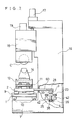
- FIGS. 7 to 9 depict schematically a second embodiment in which the second table 2 is mounted on the top of the first table 1, as described before.
- a pair of rails 10 for guiding the first table 1 are fixedly disposed on a bed 7, whereas another pair of rails 9 for guiding the second table 2 are fixedly disposed on the first table 1.
- a work table 12 is supported for rocking movement by the second table 2 through a pivot shaft 11.
- an arm 60 attached to the second table 2 and having a longitudinal axis coincident with the second horizontal axis (Z) of the machine extends into a column 16 through an opening in a front wall of the column 16.
- a horizontally rotatable disk 23 similar to the disk 23 employed in the first embodiment, which is secured to a top end of a vertical support shaft 25.
- the support shaft 25 is journalled rotatably and is operated to rotate by a rotating means 4 similar to that employed in the first embodiment.
- the guide member 3 set forth before is fixedly secured to the upper face of the disk 23.
- a guide-receiving member 33 similar to that employed in the first embodiment is supported by an end portion of the arm 60 rotatably about a vertical support shaft 28 and is engaged with the guide member 3 so as to permit relative sliding movement therebetween.
- the feed motor 5 set forth before is fixedly mounted on an end face of the bed 7 for driving the first table 1 to slide.
- the other parts of the second embodiment are fashioned similarly to the corresponding parts of the first embodiment and are designated by like numerals.
- the table assembly according to this embodiment may also be drived to slide along a desired diagonal direction as well as along the left and right direction.
Landscapes
- Engineering & Computer Science (AREA)
- Mechanical Engineering (AREA)
- Machine Tool Units (AREA)
- Gear Processing (AREA)
Applications Claiming Priority (2)
| Application Number | Priority Date | Filing Date | Title |
|---|---|---|---|
| JP63142402A JPH01310831A (ja) | 1988-06-09 | 1988-06-09 | 歯車加工機のテーブル送り装置 |
| JP142402/88 | 1988-06-09 |
Publications (2)
| Publication Number | Publication Date |
|---|---|
| EP0346146A2 true EP0346146A2 (fr) | 1989-12-13 |
| EP0346146A3 EP0346146A3 (fr) | 1992-01-02 |
Family
ID=15314512
Family Applications (1)
| Application Number | Title | Priority Date | Filing Date |
|---|---|---|---|
| EP19890305868 Withdrawn EP0346146A3 (fr) | 1988-06-09 | 1989-06-09 | Appareil pour le déplacement des tables des machines pour le finissage de roues dentées |
Country Status (3)
| Country | Link |
|---|---|
| US (1) | US4971488A (fr) |
| EP (1) | EP0346146A3 (fr) |
| JP (1) | JPH01310831A (fr) |
Families Citing this family (6)
| Publication number | Priority date | Publication date | Assignee | Title |
|---|---|---|---|---|
| US5400844A (en) * | 1993-02-11 | 1995-03-28 | Pollock; R. Bruce | Fastening device - tool holder |
| US5913646A (en) * | 1998-05-29 | 1999-06-22 | Precast Solutions, Inc. | Table extensions for use with a milling machine |
| US6530303B1 (en) | 1999-06-10 | 2003-03-11 | Black & Decker Inc. | Table saw |
| TWM326452U (en) * | 2007-07-04 | 2008-02-01 | L K Machinery Corp | Main body of a working machine |
| TWI586463B (zh) * | 2015-01-06 | 2017-06-11 | Chen Peng-Ren | CNC double spindle drive |
| US11103060B1 (en) | 2020-11-12 | 2021-08-31 | Elite Modern | Extended table with a gear assembly |
Citations (5)
| Publication number | Priority date | Publication date | Assignee | Title |
|---|---|---|---|---|
| US1443899A (en) * | 1921-02-12 | 1923-01-30 | Kusold Charles | Milling machine |
| US2581700A (en) * | 1947-08-11 | 1952-01-08 | Nat Broach & Mach | Apparatus for finishing gears |
| DE1127680B (de) * | 1958-10-15 | 1962-04-12 | Erich Tillmanns | Planetengetriebe zur Zwangsfuehrung zweier Ordinatentriebe eines Kreuzschlittens mit einer treibenden Welle |
| GB943478A (en) * | 1960-02-03 | 1963-12-04 | John Alfred Mills | Improvements in and relating to gear shaving or gear finishing machines |
| GB1087708A (en) * | 1965-09-02 | 1967-10-18 | John Alfred Mills | Improvements in gear shaving machines |
Family Cites Families (7)
| Publication number | Priority date | Publication date | Assignee | Title |
|---|---|---|---|---|
| US1032933A (en) * | 1910-12-10 | 1912-07-16 | Patrick J O'brien | Tool-directing machine. |
| US1931730A (en) * | 1930-12-10 | 1933-10-24 | Landis Tool Co | Means for setting planer heads |
| US2612080A (en) * | 1946-09-03 | 1952-09-30 | Nat Broach & Mach | Gear finishing machine |
| US2957362A (en) * | 1957-10-18 | 1960-10-25 | Advance Prod Corp | Die sinking table |
| JPS5421036A (en) * | 1977-07-18 | 1979-02-16 | Uotaman Kk | Method of conveying sludge under pressure |
| DE8322510U1 (de) * | 1983-08-04 | 1984-09-13 | Carl Hurth Maschinen- und Zahnradfabrik GmbH & Co, 8000 München | Maschine zum Feinbearbeiten der Zahnflanken von verzahnten Werkstücken |
| JP2668768B2 (ja) * | 1993-03-30 | 1997-10-27 | ベクターセミコン株式会社 | 電気的特性測定用プローブ装置 |
-
1988
- 1988-06-09 JP JP63142402A patent/JPH01310831A/ja active Pending
-
1989
- 1989-04-10 US US07/335,271 patent/US4971488A/en not_active Expired - Fee Related
- 1989-06-09 EP EP19890305868 patent/EP0346146A3/fr not_active Withdrawn
Patent Citations (5)
| Publication number | Priority date | Publication date | Assignee | Title |
|---|---|---|---|---|
| US1443899A (en) * | 1921-02-12 | 1923-01-30 | Kusold Charles | Milling machine |
| US2581700A (en) * | 1947-08-11 | 1952-01-08 | Nat Broach & Mach | Apparatus for finishing gears |
| DE1127680B (de) * | 1958-10-15 | 1962-04-12 | Erich Tillmanns | Planetengetriebe zur Zwangsfuehrung zweier Ordinatentriebe eines Kreuzschlittens mit einer treibenden Welle |
| GB943478A (en) * | 1960-02-03 | 1963-12-04 | John Alfred Mills | Improvements in and relating to gear shaving or gear finishing machines |
| GB1087708A (en) * | 1965-09-02 | 1967-10-18 | John Alfred Mills | Improvements in gear shaving machines |
Also Published As
| Publication number | Publication date |
|---|---|
| JPH01310831A (ja) | 1989-12-14 |
| US4971488A (en) | 1990-11-20 |
| EP0346146A3 (fr) | 1992-01-02 |
Similar Documents
| Publication | Publication Date | Title |
|---|---|---|
| US3232141A (en) | Machine tool | |
| JPS60141402A (ja) | 旋盤 | |
| US5346343A (en) | Milling head | |
| JPS61117058A (ja) | 研削ヘツド | |
| US4242019A (en) | Milling machine | |
| US4182205A (en) | Turret type metal working machine | |
| US3203314A (en) | Milling machine | |
| US6098258A (en) | Combined machining apparatus and machining method by using the same | |
| EP0346146A2 (fr) | Appareil pour le déplacement des tables des machines pour le finissage de roues dentées | |
| US6655246B2 (en) | Machine tool | |
| US4561815A (en) | Machine tool adjustment | |
| US4964321A (en) | Ball turner for turning lathes | |
| US5148091A (en) | Arrangement for bringing the tool-carrying end of a robot beam to a desired one of a plurality of possible predetermined positions | |
| US4304513A (en) | Milling machine including improved tool knock-out means | |
| US6324949B1 (en) | Machine tool | |
| US4677726A (en) | Milling machine apparatus | |
| US5134762A (en) | Combination alignment cylinder boring and deck milling device | |
| US4502822A (en) | Machine for the precision working of tooth surfaces of toothed workpieces | |
| CN110756914A (zh) | 一种多齿轮部轴齿双面倒棱机及加工方法 | |
| JPH0716801B2 (ja) | 複合加工用旋盤 | |
| DE3843795C2 (fr) | ||
| JP3388498B2 (ja) | 工作機械 | |
| JPH0650118Y2 (ja) | 旋回主軸台付マシニングセンタ | |
| JPS6138834A (ja) | 多頭汎用工作機械 | |
| US3570368A (en) | Duplicating apparatus |
Legal Events
| Date | Code | Title | Description |
|---|---|---|---|
| PUAI | Public reference made under article 153(3) epc to a published international application that has entered the european phase |
Free format text: ORIGINAL CODE: 0009012 |
|
| AK | Designated contracting states |
Kind code of ref document: A2 Designated state(s): DE FR GB IT |
|
| PUAL | Search report despatched |
Free format text: ORIGINAL CODE: 0009013 |
|
| AK | Designated contracting states |
Kind code of ref document: A3 Designated state(s): DE FR GB IT |
|
| 17P | Request for examination filed |
Effective date: 19920130 |
|
| 17Q | First examination report despatched |
Effective date: 19930203 |
|
| STAA | Information on the status of an ep patent application or granted ep patent |
Free format text: STATUS: THE APPLICATION IS DEEMED TO BE WITHDRAWN |
|
| 18D | Application deemed to be withdrawn |
Effective date: 19930615 |