EP0344518A1 - Séquences d'impulsions en tomographie à spin nucléaire pour la production d'images avec différentes valeurs de contraste T2 - Google Patents
Séquences d'impulsions en tomographie à spin nucléaire pour la production d'images avec différentes valeurs de contraste T2 Download PDFInfo
- Publication number
- EP0344518A1 EP0344518A1 EP89108885A EP89108885A EP0344518A1 EP 0344518 A1 EP0344518 A1 EP 0344518A1 EP 89108885 A EP89108885 A EP 89108885A EP 89108885 A EP89108885 A EP 89108885A EP 0344518 A1 EP0344518 A1 EP 0344518A1
- Authority
- EP
- European Patent Office
- Prior art keywords
- gradient
- pulse
- applying
- signal
- pulse sequence
- Prior art date
- Legal status (The legal status is an assumption and is not a legal conclusion. Google has not performed a legal analysis and makes no representation as to the accuracy of the status listed.)
- Granted
Links
- 238000001208 nuclear magnetic resonance pulse sequence Methods 0.000 title claims description 18
- 238000003325 tomography Methods 0.000 title description 5
- 238000002595 magnetic resonance imaging Methods 0.000 claims 2
- 230000005284 excitation Effects 0.000 abstract description 4
- 238000000034 method Methods 0.000 description 10
- 238000005259 measurement Methods 0.000 description 6
- 238000003384 imaging method Methods 0.000 description 3
- DGAQECJNVWCQMB-PUAWFVPOSA-M Ilexoside XXIX Chemical compound C[C@@H]1CC[C@@]2(CC[C@@]3(C(=CC[C@H]4[C@]3(CC[C@@H]5[C@@]4(CC[C@@H](C5(C)C)OS(=O)(=O)[O-])C)C)[C@@H]2[C@]1(C)O)C)C(=O)O[C@H]6[C@@H]([C@H]([C@@H]([C@H](O6)CO)O)O)O.[Na+] DGAQECJNVWCQMB-PUAWFVPOSA-M 0.000 description 2
- 238000002592 echocardiography Methods 0.000 description 2
- 230000000694 effects Effects 0.000 description 2
- 238000010438 heat treatment Methods 0.000 description 2
- 239000011159 matrix material Substances 0.000 description 2
- 229910052708 sodium Inorganic materials 0.000 description 2
- 239000011734 sodium Substances 0.000 description 2
- 239000000126 substance Substances 0.000 description 2
- 230000009466 transformation Effects 0.000 description 2
- 238000005481 NMR spectroscopy Methods 0.000 description 1
- 238000003745 diagnosis Methods 0.000 description 1
- 230000007274 generation of a signal involved in cell-cell signaling Effects 0.000 description 1
- 230000005415 magnetization Effects 0.000 description 1
- 238000001228 spectrum Methods 0.000 description 1
- XLYOFNOQVPJJNP-UHFFFAOYSA-N water Substances O XLYOFNOQVPJJNP-UHFFFAOYSA-N 0.000 description 1
Images

Classifications
-
- G—PHYSICS
- G01—MEASURING; TESTING
- G01R—MEASURING ELECTRIC VARIABLES; MEASURING MAGNETIC VARIABLES
- G01R33/00—Arrangements or instruments for measuring magnetic variables
- G01R33/20—Arrangements or instruments for measuring magnetic variables involving magnetic resonance
- G01R33/44—Arrangements or instruments for measuring magnetic variables involving magnetic resonance using nuclear magnetic resonance [NMR]
- G01R33/48—NMR imaging systems
- G01R33/54—Signal processing systems, e.g. using pulse sequences ; Generation or control of pulse sequences; Operator console
- G01R33/56—Image enhancement or correction, e.g. subtraction or averaging techniques, e.g. improvement of signal-to-noise ratio and resolution
-
- G—PHYSICS
- G01—MEASURING; TESTING
- G01R—MEASURING ELECTRIC VARIABLES; MEASURING MAGNETIC VARIABLES
- G01R33/00—Arrangements or instruments for measuring magnetic variables
- G01R33/20—Arrangements or instruments for measuring magnetic variables involving magnetic resonance
- G01R33/44—Arrangements or instruments for measuring magnetic variables involving magnetic resonance using nuclear magnetic resonance [NMR]
- G01R33/48—NMR imaging systems
- G01R33/50—NMR imaging systems based on the determination of relaxation times, e.g. T1 measurement by IR sequences; T2 measurement by multiple-echo sequences
Definitions
- the contrast of slice images generated in nuclear spin tomography depends on the relaxation times T1; T2 and the density of the investigated substance. Since the relaxation time T2 is determined, among other things, by the chemical combination of the nuclides under consideration, it represents a meaningful criterion when examining objects. By different T2 contrast, i.e. Different brightness of a pixel depending on the corresponding T2 time, images with different information content can be generated.
- a multi-echo sequence is known from the literature reference R. Graumann et al., "MAGNETIC RESONANCE IN MEDICINE” 3, 707-721 (1986), "Multiple spin echo imaging with a 2d Fourier method” Can get T2-weighted images.
- the multi-echo is achieved by a spin echo with at least two refocusing pulses.
- a method for sodium imaging is known from the literature reference SMRM 1986, Book of Abstracts, pp. 1462-1463.
- the FID signal is first evaluated directly after a 90 ° pulse, the spatial resolution being carried out using a back-projection method. Then, after a spin echo caused by a 180 ° HF pulse, a signal is read out again, with which the signal components with longer T2 times are recorded.
- the back projection method is used.
- the object of the invention is to design a pulse sequence so that data for images with different T2 contrast can be obtained after a single excitation, the measurement time should not be extended.
- the pulse sequence specified in claim 1 It is possible to simultaneously measure a gradient echo image during the measurement of a spin echo image, which has a very low T2 contrast due to a very short echo time. Compared to the separate data acquisition for images with different T2 contrast, the measurement time is reduced. Due to the simultaneous measurement, the images are independent of patient movements between measurements. Compared to the multi-echo sequence mentioned at the outset, the exposure to high-frequency heating is reduced since only one 180 ° pulse is required in each pulse sequence.
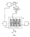
- the coils 1 to 4 generate a basic magnetic field B0, in which the body 5 of a patient to be examined is located when used for medical diagnosis.
- This is also associated with gradient coils, which are provided for generating independent, mutually perpendicular magnetic field gradients of the directions x, y and z according to the coordinate system 6.
- gradient coils 7 and 8 are drawn in the FIGURE, which together with a pair of opposing, similar gradient coils are used to generate the x gradient.
- the similar y-gradient coils lie parallel to the body 5 and above and below it, those for the z-gradient field transverse to its longitudinal axis at the head and foot ends.
- the arrangement also contains a high-frequency coil 9 used to generate and record the nuclear magnetic resonance signals.
- the measuring coil 9 is coupled via a signal amplifier 14 or a high-frequency transmitter 15 to a process computer 17 on which a display device 18 is connected to output the image.
- the components 14 and 15 form a high-frequency device 16 for signal generation and recording.
- a switch 19 enables switching from transmit to receive mode.
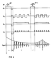
- a pulse sequence for actuating the nuclear spin tomograph In a first step, a high-frequency pulse RF1 together with a gradient G z is first applied to the examination object.
- a high-frequency pulse RF1 By appropriate choice of the frequency spectrum of the high-frequency pulse RF1, only cores in a specific layer of the examination object are selectively excited.
- the signal to be read out later has its maximum amplitude if the high-frequency pulse RF1 is dimensioned such that a flip angle of 90 ° is produced. However, smaller flip angles are also possible.
- a second step b the gradient G z is reversed in order to reverse the dephasing of the spins in the z direction caused by the gradient G z in step a).
- a negative gradient G y is created, which causes the spins to be dephased in the y direction.
- a gradient G x is applied, which serves as a phase coding gradient for the x direction. The entire sequence is carried out several times, as will be explained in more detail below, the amplitude of the gradient G x changing in each sequence.
- a third step c) the direction of the gradient G y is finally reversed, so that the previous dephasing in the y direction is canceled and a so-called gradient echo is received as signal S1.
- the amplitude of the signal S1 at full rephasing corresponds to the FID signal, so that it can also be said that this signal is read out under the envelope of the FID signal.
- This first signal S1 points a relatively low T2 contrast because it is read out close to the excitation pulse.
- a further high-frequency pulse RF2 is radiated in under the effect of a gradient G z .
- the high-frequency pulse and the gradient G z are dimensioned in the exemplary embodiment so that the same layer is selectively addressed as in step a).
- the RF pulse RF2 could also not be location-selective, ie without a gradient G z and very narrow-band. This could be used to selectively refocus the signal from fat or water.
- the high-frequency pulse RF2 is dimensioned such that it preferably corresponds to a flip angle of 180 °. The amplitude of the subsequent readout signal thus becomes maximum. However, deviations from the flip angle of 180 ° are also possible.
- the signal S2 is now much more T2-weighted because the distance to the excitation pulse RF1 is much larger. This increases the difference in brightness, i.e. the contrast between pixels with different T2 times.
- the magnetization already prepared for the imaging is refocused by the high-frequency pulse RF2 and a second echo is measured in the form of the signal S2.
- This sequence makes it possible to simultaneously measure a gradient echo image with a significantly lower T2 contrast in the measurement time for a spin echo image.
- the known multiple echo method described at the beginning does not use a second 180 ° high-frequency pulse, and thus the associated high-frequency heating of the patient and the problems with stimulated echoes are avoided.
- a complete sectional view of the examination object can now be obtained independently of one another from a set of signals S1 and a set of signals S2.
- the signals S1, S2 are sampled and each stored in a row in a matrix.
- a new line is formed for each sequence with the phase coding gradient G x continued .
- An image can be obtained from the two matrices created in this way by two-dimensional Fourier transformation.
- a corresponding method is described, for example, in US Pat. No. 4,070,611.
- the image based on the signals S1 has a significantly smaller T2 contrast than the image based on the signals S2. This gives you two images with different diagnostic information without extending the examination time.
- step c) shows a further exemplary embodiment of the invention.
- the direction of the gradient G y is reversed several times.
- a spin echo signal S1, S1 ', S1 ⁇ is generated.
- Each of these signals can in turn be used to generate its own image, so that you can get multiple images with different T2 contrast.
- a high-frequency pulse RF1 preferably a 90 ° pulse, is also initially radiated.
- the simultaneous action of a gradient G z makes this high-frequency pulse RF1 layer-selective.
- step b the gradient G z is reversed in order to reverse the dephasing of the spins in the z direction taking place in step a).
- a negative gradient G x or G x ' is switched on for prephasing in the x direction.
- a gradient G y is created which is inverted several times.
- a different phase is impressed on the spins in the x-direction after each inversion, so that after a sufficient number of inversions after a single high-frequency pulse RF1, the complete information for an image is obtained.
- the phase information can be stamped in two ways. One possibility is to leave a weak phase coding gradient g x switched on during the entire readout time. Since the amplitude-time integral of the phase coding gradient is decisive for the phase, the phase rotation increases with the number of gradient echoes. Another possibility is to switch on a small phase encoding pulse with each gradient reversal, which is designated G x 'in FIG. 4.
- a second RF pulse RF2 which preferably generates a flip angle of 180 °, is radiated in a step d).
- a gradient G z is switched on again, so that the high-frequency pulse RF2 is also frequency-selective.
- This high-frequency pulse RF2 is followed in step e) by a spin echo, so that the subsequent signals S2 are read out under the envelope of the spin echo.
- a gradient G y with alternating polarity is switched on, so that a series of echo signals are generated again.
- step e the complete information for generating a sectional image is also obtained.
- the image reconstruction can in turn be carried out by entering the sampled signal values in a matrix and a subsequent two-dimensional Fourier transformation.
- the images obtained from the signals in step c) and from the signals in step e) in turn differ by a different T2 contrast and thus have different diagnostic information content.
- each of the pictures has specific advantages and disadvantages.
- the images obtained under the envelope of the FID signal based on the signals in step c) have higher amplitudes, but are more susceptible to inhomogeneities in the basic field.
- the signals obtained in step e) under the envelope of the spin echo are less sensitive to basic magnetic field inhomogeneities, but show more T2-weighted images. Because two different images are obtained with the method according to the invention, the advantages of the respective image can be used.
Landscapes
- Physics & Mathematics (AREA)
- High Energy & Nuclear Physics (AREA)
- Condensed Matter Physics & Semiconductors (AREA)
- General Physics & Mathematics (AREA)
- Health & Medical Sciences (AREA)
- General Health & Medical Sciences (AREA)
- Nuclear Medicine, Radiotherapy & Molecular Imaging (AREA)
- Radiology & Medical Imaging (AREA)
- Engineering & Computer Science (AREA)
- Signal Processing (AREA)
- Magnetic Resonance Imaging Apparatus (AREA)
Applications Claiming Priority (2)
| Application Number | Priority Date | Filing Date | Title |
|---|---|---|---|
| DE3818375 | 1988-05-30 | ||
| DE3818375 | 1988-05-30 |
Publications (2)
| Publication Number | Publication Date |
|---|---|
| EP0344518A1 true EP0344518A1 (fr) | 1989-12-06 |
| EP0344518B1 EP0344518B1 (fr) | 1995-07-19 |
Family
ID=6355441
Family Applications (1)
| Application Number | Title | Priority Date | Filing Date |
|---|---|---|---|
| EP89108885A Expired - Lifetime EP0344518B1 (fr) | 1988-05-30 | 1989-05-17 | Séquences d'impulsions en tomographie à spin nucléaire pour la production d'images avec différentes valeurs de contraste T2 |
Country Status (3)
| Country | Link |
|---|---|
| US (1) | US4901020A (fr) |
| EP (1) | EP0344518B1 (fr) |
| DE (1) | DE58909347D1 (fr) |
Cited By (5)
| Publication number | Priority date | Publication date | Assignee | Title |
|---|---|---|---|---|
| EP0515197A1 (fr) * | 1991-05-22 | 1992-11-25 | General Electric Company | Acquisition d'images multiples par balayages rapides d'echo de spin RMN |
| EP0496501A3 (en) * | 1991-01-25 | 1993-03-03 | The Board Of Trustees Of The Leland Stanford Junior University | Magnetic resonance imaging of short t2 species with improved contrast |
| EP0571212A1 (fr) * | 1992-05-22 | 1993-11-24 | General Electric Company | Imagerie par RMN simultanée à double contraste en échos de spin rapide |
| EP0675372A1 (fr) * | 1994-03-31 | 1995-10-04 | Shimadzu Corporation | Appareil d'imagerie par résonance magnétique |
| DE102012203782A1 (de) * | 2012-03-12 | 2013-09-26 | Siemens Aktiengesellschaft | Verfahren zur Durchführung einer kombinierten Magnetresonanz-Positronenemissions-Tomographie |
Families Citing this family (22)
| Publication number | Priority date | Publication date | Assignee | Title |
|---|---|---|---|---|
| GB2228090B (en) * | 1989-02-01 | 1993-09-22 | Gen Electric Co Plc | Magnetic resonance methods |
| EP0722093A1 (fr) * | 1989-12-01 | 1996-07-17 | Siemens Aktiengesellschaft | Procédé pour le fonctionnement d'un appareil de tomographie à spin nucléaire avec un circuit résonant pour la production de gradients de champs |
| US5214382A (en) * | 1990-02-23 | 1993-05-25 | Baylor Research Institute | Magnetic resonance imaging with selective contrast enhancement |
| US5066914A (en) * | 1990-03-26 | 1991-11-19 | General Electric Company | Gradient amplifier system with flexible amplifier allocation |
| US5270654A (en) * | 1991-07-05 | 1993-12-14 | Feinberg David A | Ultra-fast multi-section MRI using gradient and spin echo (grase) imaging |
| JP3153574B2 (ja) * | 1991-08-23 | 2001-04-09 | 株式会社東芝 | 磁気共鳴映像装置 |
| EP0576712A1 (fr) * | 1992-07-03 | 1994-01-05 | Siemens Aktiengesellschaft | Séquence d'impulsions d'imagérie rapide pour la tomographie à spin nucléaire |
| EP0633480A1 (fr) * | 1993-07-09 | 1995-01-11 | Koninklijke Philips Electronics N.V. | Suppression d'artefacts dans l'imagerie par résonance magnétique GRASE |
| DE4327321C1 (de) * | 1993-08-13 | 1994-10-27 | Siemens Ag | Pulssequenz für Kernspintomographiegeräte |
| JPH07323021A (ja) * | 1994-05-31 | 1995-12-12 | Shimadzu Corp | Mrイメージング装置 |
| US5594336A (en) * | 1995-06-02 | 1997-01-14 | Picker International, Inc. | Three point technique using spin and gradient echoes for water/fat separation |
| US5680045A (en) * | 1995-07-20 | 1997-10-21 | Feinberg David A | Grase-type MR pulse sequences |
| US5602476A (en) * | 1995-08-17 | 1997-02-11 | Picker International, Inc. | Ultra-fast MR imaging data acquisition scheme using mixed bandwidth data |
| US5818230A (en) * | 1996-07-02 | 1998-10-06 | The Trustees Of Columbia University In The City Of New York | Nuclear magnetic resonance pulse sequence for acquiring a multiple-quantum filtered image |
| US6121775A (en) * | 1998-06-16 | 2000-09-19 | Beth Israel Deaconess Medical Center, Inc. | MRI imaging method and apparatus |
| US6252400B1 (en) * | 1999-03-18 | 2001-06-26 | Picker International, Inc. | Spin and field echo (safe) FSE |
| US6560477B1 (en) | 2000-03-17 | 2003-05-06 | The Regents Of The University Of California | Joint imaging system utilizing magnetic resonance imaging and associated methods |
| USRE45725E1 (en) | 2000-12-21 | 2015-10-06 | University Of Virginia Patent Foundation | Method and apparatus for spin-echo-train MR imaging using prescribed signal evolutions |
| USRE47178E1 (en) | 2000-12-21 | 2018-12-25 | University Of Virginia Patent Foundation | Method and apparatus for spin-echo-train MR imaging using prescribed signal evolutions |
| DE10112880A1 (de) * | 2001-03-15 | 2002-10-02 | Forschungszentrum Juelich Gmbh | Verfahren zur Untersuchung einer Probe mittels Erzeugung einer Bildgebungssequenz |
| AU2002338376A1 (en) * | 2001-04-06 | 2002-10-21 | Lawrence R. Frank | Method for analyzing mri diffusion data |
| DE102015223658B4 (de) * | 2015-11-30 | 2017-08-17 | Siemens Healthcare Gmbh | Verfahren zum Erfassen von Magnetresonanz-Signalen eines Untersuchungsobjekts |
Citations (4)
| Publication number | Priority date | Publication date | Assignee | Title |
|---|---|---|---|---|
| EP0191431A2 (fr) * | 1985-02-12 | 1986-08-20 | Max-Planck-Gesellschaft zur Förderung der Wissenschaften e.V. | Méthode et dispositif d'acquisition rapide de données de résonnance de spin pour un examen d'un objet pour résolution spatiale |
| EP0232946A2 (fr) * | 1986-02-12 | 1987-08-19 | Philips Patentverwaltung GmbH | Procédé pour déterminer la distribution spatiale et spectrale de la magnétisation nucléaire dans une région d'examen et dispositif pour la mise en oeuvre du procédé |
| DE3718344A1 (de) * | 1986-06-04 | 1987-12-10 | Hitachi Ltd | Abbildungsverfahren fuer magnetische kernresonanz |
| EP0255220A2 (fr) * | 1986-06-27 | 1988-02-03 | Picker International, Inc. | Imagerie pour résonance magnétique |
Family Cites Families (6)
| Publication number | Priority date | Publication date | Assignee | Title |
|---|---|---|---|---|
| JPS5946546A (ja) * | 1982-09-09 | 1984-03-15 | Yokogawa Hokushin Electric Corp | 核磁気共鳴による検査方法及び検査装置 |
| NL8203519A (nl) * | 1982-09-10 | 1984-04-02 | Philips Nv | Werkwijze en inrichting voor het bepalen van een kernmagnetisatieverdeling in een deel van een lichaam. |
| US4689567A (en) * | 1984-06-01 | 1987-08-25 | Advanced Nmr Systems, Inc. | NMR Fourier imaging from multiple echoes |
| US4609872A (en) * | 1984-08-10 | 1986-09-02 | General Electric Company | NMR multiple-echo phase-contrast blood flow imaging |
| US4714081A (en) * | 1986-03-03 | 1987-12-22 | General Electric Company | Methods for NMR angiography |
| DE3864888D1 (de) * | 1987-04-30 | 1991-10-24 | Siemens Ag | Kernspin-tomographiegeraet. |
-
1989
- 1989-03-23 US US07/327,891 patent/US4901020A/en not_active Expired - Lifetime
- 1989-05-17 EP EP89108885A patent/EP0344518B1/fr not_active Expired - Lifetime
- 1989-05-17 DE DE58909347T patent/DE58909347D1/de not_active Expired - Fee Related
Patent Citations (4)
| Publication number | Priority date | Publication date | Assignee | Title |
|---|---|---|---|---|
| EP0191431A2 (fr) * | 1985-02-12 | 1986-08-20 | Max-Planck-Gesellschaft zur Förderung der Wissenschaften e.V. | Méthode et dispositif d'acquisition rapide de données de résonnance de spin pour un examen d'un objet pour résolution spatiale |
| EP0232946A2 (fr) * | 1986-02-12 | 1987-08-19 | Philips Patentverwaltung GmbH | Procédé pour déterminer la distribution spatiale et spectrale de la magnétisation nucléaire dans une région d'examen et dispositif pour la mise en oeuvre du procédé |
| DE3718344A1 (de) * | 1986-06-04 | 1987-12-10 | Hitachi Ltd | Abbildungsverfahren fuer magnetische kernresonanz |
| EP0255220A2 (fr) * | 1986-06-27 | 1988-02-03 | Picker International, Inc. | Imagerie pour résonance magnétique |
Non-Patent Citations (1)
| Title |
|---|
| MAGNETIC RESONANCE IN MEDICINE, Band 3, Nr. 4, August 1986, Seiten 707-721, Duluth, MN, US; R. GRAUMANN et al.: "Multiple-spin-echo imaging with a 2D Fourier method" * |
Cited By (8)
| Publication number | Priority date | Publication date | Assignee | Title |
|---|---|---|---|---|
| EP0496501A3 (en) * | 1991-01-25 | 1993-03-03 | The Board Of Trustees Of The Leland Stanford Junior University | Magnetic resonance imaging of short t2 species with improved contrast |
| EP0515197A1 (fr) * | 1991-05-22 | 1992-11-25 | General Electric Company | Acquisition d'images multiples par balayages rapides d'echo de spin RMN |
| EP0571212A1 (fr) * | 1992-05-22 | 1993-11-24 | General Electric Company | Imagerie par RMN simultanée à double contraste en échos de spin rapide |
| EP0675372A1 (fr) * | 1994-03-31 | 1995-10-04 | Shimadzu Corporation | Appareil d'imagerie par résonance magnétique |
| US5521505A (en) * | 1994-03-31 | 1996-05-28 | Shimadzu Corporation | MR imaging apparatus |
| DE102012203782A1 (de) * | 2012-03-12 | 2013-09-26 | Siemens Aktiengesellschaft | Verfahren zur Durchführung einer kombinierten Magnetresonanz-Positronenemissions-Tomographie |
| US9445722B2 (en) | 2012-03-12 | 2016-09-20 | Siemens Aktiengesellschaft | Method for performing combined magnetic resonance/positron emission tomography |
| DE102012203782B4 (de) | 2012-03-12 | 2022-08-11 | Siemens Healthcare Gmbh | Verfahren zur Durchführung einer kombinierten Magnetresonanz-Positronenemissions-Tomographie |
Also Published As
| Publication number | Publication date |
|---|---|
| DE58909347D1 (de) | 1995-08-24 |
| EP0344518B1 (fr) | 1995-07-19 |
| US4901020A (en) | 1990-02-13 |
Similar Documents
| Publication | Publication Date | Title |
|---|---|---|
| EP0344518B1 (fr) | Séquences d'impulsions en tomographie à spin nucléaire pour la production d'images avec différentes valeurs de contraste T2 | |
| EP0213436B1 (fr) | Méthode de fonctionnement d'un appareil exploitant la résonance magnétique nucléaire | |
| DE10246406B4 (de) | MRI mit sich bewegendem Tisch und einer Frequenzkodierung in der z-Richtung | |
| DE19901763B4 (de) | Impulssequenz für ein Kernspintomographiegerät | |
| DE4428503C2 (de) | Diffusionsgewichtete Bildgebung mit magnetischer Resonanz | |
| EP0074022A1 (fr) | Dispositif de tomographie à spin nucléaire | |
| DE19631916A1 (de) | Echtzeit-Messung von Temperaturveränderungen im lebenden Objekt mit Magnetresonanz-Abbildung | |
| DE3642826A1 (de) | Verfahren zum erzeugen eines nmr-bildes mit verbessertem signal-rausch-verhaeltnis | |
| DE4139509C2 (de) | Bildgebendes Verfahren für ein Kernspintomographiegerät, das eine Pulssequenz nach dem Echoplanarverfahren verwendet | |
| DE4035410A1 (de) | Kernspintomographiegeraet mit einer pulssequenz nach dem echoplanarverfahren | |
| DE4024161A1 (de) | Pulssequenz zur schnellen ermittlung von bildern der fett- und wasserverteilung in einem untersuchungsobjekt mittels der kernmagnetischen resonanz | |
| DE68927874T2 (de) | Vorrichtung zur Bilderzeugung mittels magnetischer Resonanz | |
| EP0288861B1 (fr) | Appareil d'imagerie par résonance magnétique nucléaire | |
| DE69023683T2 (de) | Verfahren zur Bilderzeugung mit magnetischer Resonanz. | |
| EP0199202B1 (fr) | Dispositif de résonance de spin nucléaire | |
| DE3914351C2 (fr) | ||
| EP0425611A1 (fr) | Procede d'enregistrement de spectres de resonance magnetique et resolution graphique. | |
| DE19511794B4 (de) | Verfahren zur Gewinnung von Bilddaten in einem Kernspintomographiegerät und Kernspintomographiegerät zur Durchführung des Verfahrens | |
| WO1990013825A1 (fr) | Procede d'enregistrement de spectres de resonance de spins | |
| EP3839545A1 (fr) | Réduction d'artefact dans la technique d'écho de spin de l'imagerie par résonance magnétique du système nerveux central | |
| EP0355508B1 (fr) | Séquence d'impulsions pour la mesure de l'évolution temporelle d'un écoulement à l'intérieur d'un vaisseau utilisant la résonance magnétique nucléaire | |
| DE19962848C2 (de) | Echo-Planar-Bildgebungsverfahren | |
| DE19962847A1 (de) | Bildgebungsverfahren | |
| DE3539991A1 (de) | Verfahren zur aufzeichnung der materialeigenschaften eines zu untersuchenden gegenstandes | |
| DE4004184C2 (de) | Verfahren zur Messung des räumlichen Magnetfeldverlaufs in einem Kernspin-Tomographen |
Legal Events
| Date | Code | Title | Description |
|---|---|---|---|
| PUAI | Public reference made under article 153(3) epc to a published international application that has entered the european phase |
Free format text: ORIGINAL CODE: 0009012 |
|
| AK | Designated contracting states |
Kind code of ref document: A1 Designated state(s): DE GB |
|
| 17P | Request for examination filed |
Effective date: 19900307 |
|
| 17Q | First examination report despatched |
Effective date: 19920326 |
|
| GRAA | (expected) grant |
Free format text: ORIGINAL CODE: 0009210 |
|
| AK | Designated contracting states |
Kind code of ref document: B1 Designated state(s): DE GB |
|
| PG25 | Lapsed in a contracting state [announced via postgrant information from national office to epo] |
Ref country code: GB Effective date: 19950719 |
|
| REF | Corresponds to: |
Ref document number: 58909347 Country of ref document: DE Date of ref document: 19950824 |
|
| GBV | Gb: ep patent (uk) treated as always having been void in accordance with gb section 77(7)/1977 [no translation filed] |
Effective date: 19950719 |
|
| PLBE | No opposition filed within time limit |
Free format text: ORIGINAL CODE: 0009261 |
|
| STAA | Information on the status of an ep patent application or granted ep patent |
Free format text: STATUS: NO OPPOSITION FILED WITHIN TIME LIMIT |
|
| 26N | No opposition filed | ||
| PGFP | Annual fee paid to national office [announced via postgrant information from national office to epo] |
Ref country code: DE Payment date: 20040719 Year of fee payment: 16 |
|
| APAH | Appeal reference modified |
Free format text: ORIGINAL CODE: EPIDOSCREFNO |
|
| PG25 | Lapsed in a contracting state [announced via postgrant information from national office to epo] |
Ref country code: DE Free format text: LAPSE BECAUSE OF NON-PAYMENT OF DUE FEES Effective date: 20051201 |