US4901020A - Pulse sequence for operating a nuclear magnetic resonance tomography apparatus for producing images with different T2 contrast - Google Patents
Pulse sequence for operating a nuclear magnetic resonance tomography apparatus for producing images with different T2 contrast Download PDFInfo
- Publication number
- US4901020A US4901020A US07/327,891 US32789189A US4901020A US 4901020 A US4901020 A US 4901020A US 32789189 A US32789189 A US 32789189A US 4901020 A US4901020 A US 4901020A
- Authority
- US
- United States
- Prior art keywords
- gradient
- radio
- generating
- pulse
- directional sign
- Prior art date
- Legal status (The legal status is an assumption and is not a legal conclusion. Google has not performed a legal analysis and makes no representation as to the accuracy of the status listed.)
- Expired - Lifetime
Links
Images
Classifications
-
- G—PHYSICS
- G01—MEASURING; TESTING
- G01R—MEASURING ELECTRIC VARIABLES; MEASURING MAGNETIC VARIABLES
- G01R33/00—Arrangements or instruments for measuring magnetic variables
- G01R33/20—Arrangements or instruments for measuring magnetic variables involving magnetic resonance
- G01R33/44—Arrangements or instruments for measuring magnetic variables involving magnetic resonance using nuclear magnetic resonance [NMR]
- G01R33/48—NMR imaging systems
- G01R33/54—Signal processing systems, e.g. using pulse sequences ; Generation or control of pulse sequences; Operator console
- G01R33/56—Image enhancement or correction, e.g. subtraction or averaging techniques, e.g. improvement of signal-to-noise ratio and resolution
-
- G—PHYSICS
- G01—MEASURING; TESTING
- G01R—MEASURING ELECTRIC VARIABLES; MEASURING MAGNETIC VARIABLES
- G01R33/00—Arrangements or instruments for measuring magnetic variables
- G01R33/20—Arrangements or instruments for measuring magnetic variables involving magnetic resonance
- G01R33/44—Arrangements or instruments for measuring magnetic variables involving magnetic resonance using nuclear magnetic resonance [NMR]
- G01R33/48—NMR imaging systems
- G01R33/50—NMR imaging systems based on the determination of relaxation times, e.g. T1 measurement by IR sequences; T2 measurement by multiple-echo sequences
Definitions
- the present invention relates to a pulse sequence for use in operating a nuclear magnetic resonance tomography apparatus, and in particular to such a pulse sequence for operating the apparatus to produce images with different T 2 contrast.
- a multi-echo sequence wherein images which are T 2 -weighted to different degrees are obtained is described in "Multiple Spin Echo Imaging With A 2d Fourier Method," Graumann et al., Magnetic Resonance in Medicine, Vol. 3, pages 707-721 (1986).
- the multi-echo in this method is achieved using a spin echo with at least two refocusing pulses.
- a method for sodium imaging is described in "Sodium Magnetic Resonance Imaging of Human Body,” Ra et al., SMRM (1986), Book of Abstracts, pages 1462-1463.
- a problem with this type of imaging is that sodium has extremely short T 2 components.
- the FID signal is first directly evaluated after a 90° pulse, and the topical resolution is undertaken using a back-projection method. After a spin echo produced by a 180° RF pulse, a signal is again read out, by which signal components having longer T 2 times are acquired. The same back-projection method is then used again.
- a pulse sequence for operating a nuclear magnetic resonance tomography apparatus wherein a first, selective radio-frequency pulse is generated together with a gradient pulse in the z-direction. These pulses function as slice selection gradients.
- a first gradient pulse in y-direction is then application for dephasing the spin in the y-direction. This pulse is generated simultaneously with a gradient pulse in the x-direction, having an amplitude-time integral varying from step-to-step for phase coding of the spins in the small x-direction.
- a second gradient pulse in the y-direction in then generated, having a directional sign opposite to the first gradient pulse in the y-direction.
- a radio signal is read-out corresponding to a first spin echo.
- a second radio-frequency pulse is then generated, having a flip angle of approximately 180°.
- a third gradient pulse y-direction having the same directional sign as the second gradient pulse in the y-direction (i.e., opposite to that of the first gradient pulse in the y-direction) is then generated, during which read-out of a second radio signal corresponding to a second spin echo is undertaken.
- the second gradient in the y-direction can be multiply reversed in directional sign, thereby generating further data sets corresponding to each sign reversal, so that more than two images having different T 2 contrast can be generated.
- the method of obtaining images with different T 2 contrast can be combined with a known image acquisition method referred to as the echo-planar method.
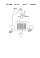
- FIG. 1 is a schematic block diagram of a nuclear magnetic resonance tomography apparatus operable using the pulse sequence described in herein.
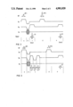
- FIG. 2 is a first embodiment of a pulse sequence in accordance with the principles of the present invention.
- FIG. 3 is a second embodiment of a pulse sequence in accordance with the principles of the present invention.
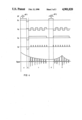
- FIG. 4 is a third embodiment of a pulse sequence in accordance with the principles of the present invention.
- FIG. 1 A nuclear magnetic resonance tomography apparatus, operable using the various embodiments of the pulse sequence described below, is schematically shown in FIG. 1.
- the apparatus includes coils 1, 2, 3 and 4 for generating a fundamental magnetic field in which, for medical diagnostics, a patient 5 to be examined in disposed.
- Gradient coils are also present for generating independent, orthogonal magnetic field gradients in the x, y and z directions, as indicated by the axes 6.
- the gradient coils 7 and 8 are shown in FIG. 1, which generate the x-gradient together with a pair of identical gradient coils on the opposite side of the patient 5.
- Similar y-gradient coils (not shown) are disposed parallel to the patient 5 above and below by patient 5.
- Similar z-gradient field coils (not shown) are disposed transversely to the longitudinal axis of the patient 5 at the head and feet of the patient 5.
- the apparatus also includes a radio-frequency coil 9 for generating and picking up the nuclear magnetic resonance signals.
- the coils 1, 2, 3, 4, 7, 8 and 9 bounded by the dot-dash line 10 (plus the other gradient coils which are not shown) represent the actual examination instrument in which the patient 5 is disposed.
- This instrument is operated in combination with various electrical components, including a power supply 11 for the fundamental field coils and a power supply 12 for the gradient field coils.
- the measuring coil 9 is connected to a process computer 17 via an RF unit 16, which includes an amplifier 14 used during signal reception, and a transmitter 15 used during signal transmission.
- a switch 19 connects the pick-up coil 9 to either the amplifier 14 or the transmitter 15 depending upon whether the unit is in a receiving or transmitting mode.
- the data acquired during the receiving mode are supplied to the computer 17, which constructs an image therefrom, which is represented on a display 18.
- FIG. 2 A first embodiment of a pulse sequence in accordance with the principles of the present invention for operating the apparatus shown in FIG. 1 is shown in FIG. 2.
- a radio-frequency pulse RF1 and a gradient G z are simultaneously generated and applied to the examination subject.
- the signal to be read out later has a maximum amplitude when the radio-frequency pulse RF1 is dimensioned so that a flip angle of 90° arises. Smaller flip angles are, however, possible.
- This first step is designated a in FIG. 2.
- a second step b the gradient G z , is reversed to cancel the dephasing of the spin in the z-direction produced in step a by the gradient G z .
- a negative gradient G y is applied, causing dephasing of the spin in the y-direction.
- a gradient G x is also simultaneously applied, which serves as a phase coding gradient in the x-direction.
- the overall sequence as described again below, is multiply executed, with the amplitude of the gradient G x changing in each sequence.
- a third step c the direction of the gradient G y in reversed so that the previous dephasing in the y-direction is canceled.
- a signal referred to as a gradient echo is received as a signal S1.
- the amplitude of the signal S1, given complete dephasing, corresponds to the FID signal.
- the signal S1 can thus be said to be read out under the envelope of the FID signal.
- This first signal S1 exhibits a relatively low T 2 contrast, because it is read out close to the excitation pulse.
- a further radio-frequency pulse RF2 is generated simultaneously with a gradient G z .
- the radio-frequency pulse RF2 and the gradient G z are dimensioned so that, in the exemplary embodiment of FIG. 2, the same slice is again selected as was selected in step a.
- the radio-frequency pulse RF2 could be nontopically selective, i.e., without the gradient G z , and could also be alternatively have an extremely narrow bandwidth.
- signals corresponding to fat tissue or water could thus be refocused.
- the band width could be 300 Hz at a field strength of 2T.
- the radio-frequency pulse RF2 is dimensioned so that it preferably corresponds to a flip angle of 180°.
- a spin echo which is universally standard in nuclear magnetic resonance tomography is produced by rephasing with the radio-frequency pulse RF2 having a flip angle of approximately 180°.
- This spin echo is read out as a signal S2 in the following step e, under the influence of a gradient G y which functions as a read-out gradient. Because the second read-out also occurs during the spin echo, the further signal S2 is also read out under the envelope of the spin echo.
- the signal S2 is significantly more heavily T 2 -weighted because the distance (time duration) from the excitation pulse RF1 is significantly greater than that of the signal S1.
- the brightness difference i.e., the contrast between picture elements having different T 2 time, is thus increased.
- the magnetization which has already been prepared for the imaging is thus refocused by the radio-frequency pulse RF2, and a second echo in the form of the signal S2 is measured.
- This sequence permits measurement of a gradient echo image having significantly lower T 2 contrast simultaneously in the measuring time for a spin echo image.
- a second 180° radio-frequency pulse is not employed, and thus radio-frequency heating of the examination subject associated with such a second 180° radio-frequency pulse is not present, and problems associated with stimulated echoes are thus avoided.
- a complete tomogram of the selected slice of the examination subject can now be acquired from a set of signals S1 and set of signals S2. These data sets are acquired independently of each other.
- the signals S1 and S2, upon read-out thereof, are respectively stored in the row of a memory matrix.
- a new row is formed for each sequence given an incremented phase coding gradient G x .
- An image can be acquired by two-dimensional Fourier transformation from the two matrices generated in this manner.
- Such a suitable image acquiring method is described, for example, in U.S. Pat. No. 4,070,611.
- the image based on the signals S1 exhibits significantly lower T 2 contrast than the image based on the signals S2. Two images having different diagnostic informational content are thus obtained without lengthening the examination time.
- FIG. 3 A further embodiment of a pulse sequence in accordance with the principles of the present invention is shown in FIG. 3. This embodiment is the same as that shown in FIG. 2, with the exception the in step c the direction of the gradient G y is multiply reversed. A respective spin echo signal S1, S1' and S1" is generated with each gradient reversal. Each of these signals can be used to generate a separate image, so that more than two images having different T 2 contrast can be obtained.
- FIG. 4 A further embodiment of a pulse sequence is shown in FIG. 4, which employs the above-described method for obtaining images with different T 2 contrast in the context of the known echo-planar method of image acquisition, this known method of image acquisition being described in U.S. Pat. No. 4,451,788.
- a radio-frequency pulse Rf1 is generated, preferably a 90° pulse.
- a gradient G z is simultaneously generated, so that the radio-frequency pulse RF1 is slice-selective.
- the gradient G z is reversed to cancel the dephasing of the spin in the z-direction which occurred in step a.
- a negative gradient G x or G x' is generated for pre-phasing in the x-direction.
- a gradient G y which is multiply inverted is applied in the following step c.
- a different phase is therefore impressed on the spins in the x-direction after each inversion, so that complete data for an image are obtained following an adequate number of inversions after a single radio-frequency pulse RF1.
- the impressing of the phase information can occur in two ways.
- phase rotation increases with the number of gradient echoes.
- a further possibility is to switch a small phase coding pulse on at each gradient reversal, these phase coding pulses being referenced G x' in FIG. 4.
- the pulse length of G x' in the order of about 100 ⁇ sec.
- a second radio-frequency pulse RF2 which preferably produces a flip angle 180°, is generated in step d.
- a gradient G z is again switched on simultaneously, so that the radio-frequency RF2 is also frequency-selective.
- this radio-frequency pulse RF2 is followed by a spin echo, so that the following signals S2 are read out under the envelope of the spin echo.
- a gradient G y having alternating polarity is again generated, so that a series of echo signals again arises.
- Either a continuous phase coding gradient G x or a phase coding gradient G x' having individual pulses can be used given polarity change of the gradient G y .
- the complete set of data for generating a tomogram is obtained in step e.
- Image reconstruction can again be undertaken by entering the signal values into a matrix, followed by two dimensional Fourier transformation.
- the images acquired from the signals in step c and from the signals in step e again exhibit different T 2 contrast, and thus have different diagnostic informational content.
- Each of these images has specific advantages and disadvantages.
- the images acquired under the envelope of the FID signal as a result of the signals in step c have higher amplitudes, but are more susceptible to inhomogeneities in the fundamental field.
- the signals acquired in step e under the envelope of the spin echo are less sensitive to inhomogeneities in the fundamental magnetic field, but have more heavily T 2 -weighted images.
- the advantages of each type of image can be exploited, since both images are acquired in accordance with the principles of the present invention without any lengthening of the data acquisition time.
Landscapes
- Physics & Mathematics (AREA)
- High Energy & Nuclear Physics (AREA)
- Condensed Matter Physics & Semiconductors (AREA)
- General Physics & Mathematics (AREA)
- Health & Medical Sciences (AREA)
- General Health & Medical Sciences (AREA)
- Nuclear Medicine, Radiotherapy & Molecular Imaging (AREA)
- Radiology & Medical Imaging (AREA)
- Engineering & Computer Science (AREA)
- Signal Processing (AREA)
- Magnetic Resonance Imaging Apparatus (AREA)
Applications Claiming Priority (2)
| Application Number | Priority Date | Filing Date | Title |
|---|---|---|---|
| DE3818375 | 1988-05-30 | ||
| DE3818375 | 1988-05-30 |
Publications (1)
| Publication Number | Publication Date |
|---|---|
| US4901020A true US4901020A (en) | 1990-02-13 |
Family
ID=6355441
Family Applications (1)
| Application Number | Title | Priority Date | Filing Date |
|---|---|---|---|
| US07/327,891 Expired - Lifetime US4901020A (en) | 1988-05-30 | 1989-03-23 | Pulse sequence for operating a nuclear magnetic resonance tomography apparatus for producing images with different T2 contrast |
Country Status (3)
| Country | Link |
|---|---|
| US (1) | US4901020A (fr) |
| EP (1) | EP0344518B1 (fr) |
| DE (1) | DE58909347D1 (fr) |
Cited By (24)
| Publication number | Priority date | Publication date | Assignee | Title |
|---|---|---|---|---|
| US5034691A (en) * | 1989-02-01 | 1991-07-23 | Picker International, Ltd. | Magnetic resonance methods and apparatus |
| US5066914A (en) * | 1990-03-26 | 1991-11-19 | General Electric Company | Gradient amplifier system with flexible amplifier allocation |
| US5168226A (en) * | 1991-05-22 | 1992-12-01 | General Electric | Acquisition of multiple images in fast spin echo nmr scans |
| US5214382A (en) * | 1990-02-23 | 1993-05-25 | Baylor Research Institute | Magnetic resonance imaging with selective contrast enhancement |
| US5229717A (en) * | 1992-05-22 | 1993-07-20 | General Electric Company | Simultaneous two-contrast fast spin echo NMR imaging |
| US5270654A (en) * | 1991-07-05 | 1993-12-14 | Feinberg David A | Ultra-fast multi-section MRI using gradient and spin echo (grase) imaging |
| US5298863A (en) * | 1989-12-01 | 1994-03-29 | Siemens Aktiengesellschaft | Magnetic resonance imaging apparatus having a resonant circuit for generating gradient fields, and method for operating same |
| US5337000A (en) * | 1992-07-03 | 1994-08-09 | Siemens Aktiengesellschaft | Method for fast imaging in nuclear magnetic resonance tomography |
| US5361028A (en) * | 1991-08-23 | 1994-11-01 | Kabushiki Kaisha Toshiba | Method and apparatus for high speed magnetic resonance imaging with improved image quality |
| US5523688A (en) * | 1993-08-13 | 1996-06-04 | Oliver Heid | Method for operating a magnetic resonance imaging apparatus to obtain a high T2 contrast |
| US5561370A (en) * | 1993-07-09 | 1996-10-01 | U.S. Philips Corporation | Artefact suppression in GRASE Mr imaging |
| US5594336A (en) * | 1995-06-02 | 1997-01-14 | Picker International, Inc. | Three point technique using spin and gradient echoes for water/fat separation |
| US5602476A (en) * | 1995-08-17 | 1997-02-11 | Picker International, Inc. | Ultra-fast MR imaging data acquisition scheme using mixed bandwidth data |
| US5615676A (en) * | 1994-05-31 | 1997-04-01 | Shimadzu Corporation | MR imaging method and apparatus utilizing gradient and spin echo technique |
| US5680045A (en) * | 1995-07-20 | 1997-10-21 | Feinberg David A | Grase-type MR pulse sequences |
| US5818230A (en) * | 1996-07-02 | 1998-10-06 | The Trustees Of Columbia University In The City Of New York | Nuclear magnetic resonance pulse sequence for acquiring a multiple-quantum filtered image |
| US6121775A (en) * | 1998-06-16 | 2000-09-19 | Beth Israel Deaconess Medical Center, Inc. | MRI imaging method and apparatus |
| EP1037066A2 (fr) * | 1999-03-18 | 2000-09-20 | Marconi Medical Systems, Inc. | Séquence d'impulsions pour l'imagerie par résonance magnétique |
| WO2002075347A1 (fr) * | 2001-03-15 | 2002-09-26 | Forschungszentrum Jülich GmbH | Procede d'analyse d'un echantillon faisant appel a la production d'une sequence d'imagerie |
| US6560477B1 (en) | 2000-03-17 | 2003-05-06 | The Regents Of The University Of California | Joint imaging system utilizing magnetic resonance imaging and associated methods |
| US20040051527A1 (en) * | 2000-12-21 | 2004-03-18 | Mugler Iii John P | Method and apparatus for spin-echo-train MR imaging using prescribed signal evolutions |
| US20050068031A1 (en) * | 2001-04-06 | 2005-03-31 | Frank Lawrence R. | Method for analyzing mri diffusion data |
| USRE45725E1 (en) | 2000-12-21 | 2015-10-06 | University Of Virginia Patent Foundation | Method and apparatus for spin-echo-train MR imaging using prescribed signal evolutions |
| US20170153306A1 (en) * | 2015-11-30 | 2017-06-01 | Siemens Healthcare Gmbh | Method and apparatus for acquiring magnetic resonance signals of an examination object |
Families Citing this family (3)
| Publication number | Priority date | Publication date | Assignee | Title |
|---|---|---|---|---|
| US5150053A (en) * | 1989-07-28 | 1992-09-22 | The Board Of Trustees Of The Leland Stanford Junior University | Magnetic resonance imaging of short T2 species with improved contrast |
| JP2713160B2 (ja) * | 1994-03-31 | 1998-02-16 | 株式会社島津製作所 | Mrイメージング装置 |
| DE102012203782B4 (de) * | 2012-03-12 | 2022-08-11 | Siemens Healthcare Gmbh | Verfahren zur Durchführung einer kombinierten Magnetresonanz-Positronenemissions-Tomographie |
Citations (9)
| Publication number | Priority date | Publication date | Assignee | Title |
|---|---|---|---|---|
| US4527124A (en) * | 1982-09-10 | 1985-07-02 | U.S. Philips Corporation | Method of and device for determining a nuclear magnetization distribution in a part of a body |
| US4609872A (en) * | 1984-08-10 | 1986-09-02 | General Electric Company | NMR multiple-echo phase-contrast blood flow imaging |
| EP0232946A2 (fr) * | 1986-02-12 | 1987-08-19 | Philips Patentverwaltung GmbH | Procédé pour déterminer la distribution spatiale et spectrale de la magnétisation nucléaire dans une région d'examen et dispositif pour la mise en oeuvre du procédé |
| US4689567A (en) * | 1984-06-01 | 1987-08-25 | Advanced Nmr Systems, Inc. | NMR Fourier imaging from multiple echoes |
| US4707658A (en) * | 1985-02-12 | 1987-11-17 | Max-Planck-Gesellschaft Zur Foerderung Der Wissenschaften E.V. | Method of rapid acquisition of spin resonance data for a spatially resolved investigation of an object |
| US4714081A (en) * | 1986-03-03 | 1987-12-22 | General Electric Company | Methods for NMR angiography |
| EP0255220A2 (fr) * | 1986-06-27 | 1988-02-03 | Picker International, Inc. | Imagerie pour résonance magnétique |
| US4740749A (en) * | 1986-06-04 | 1988-04-26 | Hitachi, Ltd. | NMR imaging method |
| US4825159A (en) * | 1987-04-30 | 1989-04-25 | Siemens Aktiengesellschaft | Method for operating a nuclear magnetic resonance tomography apparatus |
Family Cites Families (1)
| Publication number | Priority date | Publication date | Assignee | Title |
|---|---|---|---|---|
| JPS5946546A (ja) * | 1982-09-09 | 1984-03-15 | Yokogawa Hokushin Electric Corp | 核磁気共鳴による検査方法及び検査装置 |
-
1989
- 1989-03-23 US US07/327,891 patent/US4901020A/en not_active Expired - Lifetime
- 1989-05-17 EP EP89108885A patent/EP0344518B1/fr not_active Expired - Lifetime
- 1989-05-17 DE DE58909347T patent/DE58909347D1/de not_active Expired - Fee Related
Patent Citations (9)
| Publication number | Priority date | Publication date | Assignee | Title |
|---|---|---|---|---|
| US4527124A (en) * | 1982-09-10 | 1985-07-02 | U.S. Philips Corporation | Method of and device for determining a nuclear magnetization distribution in a part of a body |
| US4689567A (en) * | 1984-06-01 | 1987-08-25 | Advanced Nmr Systems, Inc. | NMR Fourier imaging from multiple echoes |
| US4609872A (en) * | 1984-08-10 | 1986-09-02 | General Electric Company | NMR multiple-echo phase-contrast blood flow imaging |
| US4707658A (en) * | 1985-02-12 | 1987-11-17 | Max-Planck-Gesellschaft Zur Foerderung Der Wissenschaften E.V. | Method of rapid acquisition of spin resonance data for a spatially resolved investigation of an object |
| EP0232946A2 (fr) * | 1986-02-12 | 1987-08-19 | Philips Patentverwaltung GmbH | Procédé pour déterminer la distribution spatiale et spectrale de la magnétisation nucléaire dans une région d'examen et dispositif pour la mise en oeuvre du procédé |
| US4714081A (en) * | 1986-03-03 | 1987-12-22 | General Electric Company | Methods for NMR angiography |
| US4740749A (en) * | 1986-06-04 | 1988-04-26 | Hitachi, Ltd. | NMR imaging method |
| EP0255220A2 (fr) * | 1986-06-27 | 1988-02-03 | Picker International, Inc. | Imagerie pour résonance magnétique |
| US4825159A (en) * | 1987-04-30 | 1989-04-25 | Siemens Aktiengesellschaft | Method for operating a nuclear magnetic resonance tomography apparatus |
Non-Patent Citations (4)
| Title |
|---|
| "Multiple-Spin-Echo Imaging With a 2D Fourier Method," Graumann et al., Magnetic Resonance in Medicine, vol. 3, pp. 707-721 (1986). |
| "Sodium Magnetic Resonance Imaging of Human Body," Ra et al., SMRM Book of Abstracts (1986), pp. 1462-1463. |
| Multiple Spin Echo Imaging With a 2D Fourier Method, Graumann et al., Magnetic Resonance in Medicine, vol. 3, pp. 707 721 (1986). * |
| Sodium Magnetic Resonance Imaging of Human Body, Ra et al., SMRM Book of Abstracts (1986), pp. 1462 1463. * |
Cited By (32)
| Publication number | Priority date | Publication date | Assignee | Title |
|---|---|---|---|---|
| US5034691A (en) * | 1989-02-01 | 1991-07-23 | Picker International, Ltd. | Magnetic resonance methods and apparatus |
| US5298863A (en) * | 1989-12-01 | 1994-03-29 | Siemens Aktiengesellschaft | Magnetic resonance imaging apparatus having a resonant circuit for generating gradient fields, and method for operating same |
| US5214382A (en) * | 1990-02-23 | 1993-05-25 | Baylor Research Institute | Magnetic resonance imaging with selective contrast enhancement |
| US5066914A (en) * | 1990-03-26 | 1991-11-19 | General Electric Company | Gradient amplifier system with flexible amplifier allocation |
| US5168226A (en) * | 1991-05-22 | 1992-12-01 | General Electric | Acquisition of multiple images in fast spin echo nmr scans |
| US5270654A (en) * | 1991-07-05 | 1993-12-14 | Feinberg David A | Ultra-fast multi-section MRI using gradient and spin echo (grase) imaging |
| USRE35656E (en) * | 1991-07-05 | 1997-11-11 | Brigham & Women's Hospital, Inc. | Ultra-fast multi-section MRI using gradient and spin echo (GRASE) imaging |
| US5361028A (en) * | 1991-08-23 | 1994-11-01 | Kabushiki Kaisha Toshiba | Method and apparatus for high speed magnetic resonance imaging with improved image quality |
| US5229717A (en) * | 1992-05-22 | 1993-07-20 | General Electric Company | Simultaneous two-contrast fast spin echo NMR imaging |
| US5337000A (en) * | 1992-07-03 | 1994-08-09 | Siemens Aktiengesellschaft | Method for fast imaging in nuclear magnetic resonance tomography |
| US5561370A (en) * | 1993-07-09 | 1996-10-01 | U.S. Philips Corporation | Artefact suppression in GRASE Mr imaging |
| US5523688A (en) * | 1993-08-13 | 1996-06-04 | Oliver Heid | Method for operating a magnetic resonance imaging apparatus to obtain a high T2 contrast |
| US5615676A (en) * | 1994-05-31 | 1997-04-01 | Shimadzu Corporation | MR imaging method and apparatus utilizing gradient and spin echo technique |
| US5594336A (en) * | 1995-06-02 | 1997-01-14 | Picker International, Inc. | Three point technique using spin and gradient echoes for water/fat separation |
| US5680045A (en) * | 1995-07-20 | 1997-10-21 | Feinberg David A | Grase-type MR pulse sequences |
| US5602476A (en) * | 1995-08-17 | 1997-02-11 | Picker International, Inc. | Ultra-fast MR imaging data acquisition scheme using mixed bandwidth data |
| US5818230A (en) * | 1996-07-02 | 1998-10-06 | The Trustees Of Columbia University In The City Of New York | Nuclear magnetic resonance pulse sequence for acquiring a multiple-quantum filtered image |
| US6121775A (en) * | 1998-06-16 | 2000-09-19 | Beth Israel Deaconess Medical Center, Inc. | MRI imaging method and apparatus |
| EP1037066A2 (fr) * | 1999-03-18 | 2000-09-20 | Marconi Medical Systems, Inc. | Séquence d'impulsions pour l'imagerie par résonance magnétique |
| EP1037066A3 (fr) * | 1999-03-18 | 2002-05-22 | Marconi Medical Systems, Inc. | Séquence d'impulsions pour l'imagerie par résonance magnétique |
| US6560477B1 (en) | 2000-03-17 | 2003-05-06 | The Regents Of The University Of California | Joint imaging system utilizing magnetic resonance imaging and associated methods |
| USRE45725E1 (en) | 2000-12-21 | 2015-10-06 | University Of Virginia Patent Foundation | Method and apparatus for spin-echo-train MR imaging using prescribed signal evolutions |
| US20040051527A1 (en) * | 2000-12-21 | 2004-03-18 | Mugler Iii John P | Method and apparatus for spin-echo-train MR imaging using prescribed signal evolutions |
| USRE48347E1 (en) | 2000-12-21 | 2020-12-08 | University Of Virginia Patent Foundation | Method and apparatus for spin-echo-train MR imaging using prescribed signal evolutions |
| USRE47178E1 (en) | 2000-12-21 | 2018-12-25 | University Of Virginia Patent Foundation | Method and apparatus for spin-echo-train MR imaging using prescribed signal evolutions |
| US7164268B2 (en) | 2000-12-21 | 2007-01-16 | University Of Virginia Patent Foundation | Method and apparatus for spin-echo-train MR imaging using prescribed signal evolutions |
| USRE44644E1 (en) | 2000-12-21 | 2013-12-17 | University Of Virginia Patent Foundation | Method and apparatus for spin-echo-train MR imaging using prescribed signal evolutions |
| WO2002075347A1 (fr) * | 2001-03-15 | 2002-09-26 | Forschungszentrum Jülich GmbH | Procede d'analyse d'un echantillon faisant appel a la production d'une sequence d'imagerie |
| US6992484B2 (en) | 2001-04-06 | 2006-01-31 | The Regents Of The University Of California | Method for analyzing MRI diffusion data |
| US20050068031A1 (en) * | 2001-04-06 | 2005-03-31 | Frank Lawrence R. | Method for analyzing mri diffusion data |
| US20170153306A1 (en) * | 2015-11-30 | 2017-06-01 | Siemens Healthcare Gmbh | Method and apparatus for acquiring magnetic resonance signals of an examination object |
| US10031197B2 (en) * | 2015-11-30 | 2018-07-24 | Siemens Healthcare Gmbh | Method and apparatus for acquiring magnetic resonance signals of an examination object |
Also Published As
| Publication number | Publication date |
|---|---|
| EP0344518A1 (fr) | 1989-12-06 |
| EP0344518B1 (fr) | 1995-07-19 |
| DE58909347D1 (de) | 1995-08-24 |
Similar Documents
| Publication | Publication Date | Title |
|---|---|---|
| US4901020A (en) | Pulse sequence for operating a nuclear magnetic resonance tomography apparatus for producing images with different T2 contrast | |
| US5711300A (en) | Real time in vivo measurement of temperature changes with NMR imaging | |
| US4734646A (en) | Method for obtaining T1-weighted and T2-weighted NMR images for a plurality of selected planes in the course of a single scan | |
| US4769603A (en) | Method for the operation of a nuclear magnetic resonance apparatus | |
| US5034692A (en) | Magnetic resonance imaging method for acquiring flux-compensated, T2 -w | |
| US6078176A (en) | Fast spin echo pulse sequence for diffusion weighted imaging | |
| CN100426003C (zh) | 扩散加权磁共振成像中用稳态序列确定表观扩散系数的方法 | |
| US6559642B2 (en) | Calibration method for use with sensitivity encoding MRI acquisition | |
| JP4427152B2 (ja) | Mriシステムによる画像形成方法及びmriシステム | |
| EP0188006A2 (fr) | Procédé pour renverser l'aimantation transversale résiduelle créée par l'application des gradients de champ magnétique de codage de phase,et dispositif | |
| US7443162B2 (en) | Magnetic resonance imaging method and apparatus with application of the truefisp sequence and sequential acquisition of the MR images of multiple slices of a measurement subject | |
| JPH0654828A (ja) | Nmrシステム | |
| JPS61288849A (ja) | 客体の局部分解検査のためにスピン共鳴デ−タを迅速に得る方法 | |
| US5051699A (en) | Magnetic resonance imaging system | |
| US4604579A (en) | Method and apparatus for enhanced T1 NMR measurements using repetition intervals TR related to one another by integer multiples | |
| US4520828A (en) | Nuclear magnetic resonance method and apparatus | |
| US5079505A (en) | Method in the form of a pulse sequence for fast calculation of images of the fat and water distribution in an examination subject on the basis of nuclear magnetic resonance | |
| US6169398B1 (en) | Magnetic resonance imaging apparatus and imaging method | |
| US7034532B1 (en) | Driven equilibrium and fast-spin echo scanning | |
| US5043665A (en) | Magnetic resonance imaging system | |
| US4803432A (en) | Short echo NMR imaging of sodium | |
| US4825159A (en) | Method for operating a nuclear magnetic resonance tomography apparatus | |
| US4717879A (en) | Pulse sequence for NMR image acquisition | |
| US4684892A (en) | Nuclear magnetic resonance apparatus | |
| US6046588A (en) | Magnetic resonance apparatus |
Legal Events
| Date | Code | Title | Description |
|---|---|---|---|
| AS | Assignment |
Owner name: SIEMENS AKTIENGESELLSCHAFT, MUNICH, GERMANY, A GER Free format text: ASSIGNMENT OF ASSIGNORS INTEREST.;ASSIGNORS:LADEBECK, RALF;FISCHER, HUBERTUS;SCHMITT, FRANZ;REEL/FRAME:005056/0966 Effective date: 19890309 |
|
| STCF | Information on status: patent grant |
Free format text: PATENTED CASE |
|
| FEPP | Fee payment procedure |
Free format text: PAYOR NUMBER ASSIGNED (ORIGINAL EVENT CODE: ASPN); ENTITY STATUS OF PATENT OWNER: LARGE ENTITY |
|
| FPAY | Fee payment |
Year of fee payment: 4 |
|
| FPAY | Fee payment |
Year of fee payment: 8 |
|
| FPAY | Fee payment |
Year of fee payment: 12 |