EP0344281B1 - Opto-elektronischer skalenlese-apparat - Google Patents
Opto-elektronischer skalenlese-apparat Download PDFInfo
- Publication number
- EP0344281B1 EP0344281B1 EP19890900622 EP89900622A EP0344281B1 EP 0344281 B1 EP0344281 B1 EP 0344281B1 EP 19890900622 EP19890900622 EP 19890900622 EP 89900622 A EP89900622 A EP 89900622A EP 0344281 B1 EP0344281 B1 EP 0344281B1
- Authority
- EP
- European Patent Office
- Prior art keywords
- grating
- orders
- scale
- diffraction
- grating means
- Prior art date
- Legal status (The legal status is an assumption and is not a legal conclusion. Google has not performed a legal analysis and makes no representation as to the accuracy of the status listed.)
- Expired
Links
- 230000005693 optoelectronics Effects 0.000 title claims description 8
- 238000006073 displacement reaction Methods 0.000 claims description 7
- 230000000694 effects Effects 0.000 claims description 4
- 239000011521 glass Substances 0.000 claims description 4
- 230000001427 coherent effect Effects 0.000 claims description 3
- 238000004519 manufacturing process Methods 0.000 claims description 3
- 230000000737 periodic effect Effects 0.000 claims description 3
- 238000005191 phase separation Methods 0.000 claims description 2
- 238000000926 separation method Methods 0.000 description 5
- 230000004048 modification Effects 0.000 description 2
- 238000012986 modification Methods 0.000 description 2
- 230000003287 optical effect Effects 0.000 description 2
- 238000001514 detection method Methods 0.000 description 1
- 238000002310 reflectometry Methods 0.000 description 1
Images

Classifications
-
- G—PHYSICS
- G01—MEASURING; TESTING
- G01D—MEASURING NOT SPECIALLY ADAPTED FOR A SPECIFIC VARIABLE; ARRANGEMENTS FOR MEASURING TWO OR MORE VARIABLES NOT COVERED IN A SINGLE OTHER SUBCLASS; TARIFF METERING APPARATUS; MEASURING OR TESTING NOT OTHERWISE PROVIDED FOR
- G01D5/00—Mechanical means for transferring the output of a sensing member; Means for converting the output of a sensing member to another variable where the form or nature of the sensing member does not constrain the means for converting; Transducers not specially adapted for a specific variable
- G01D5/26—Mechanical means for transferring the output of a sensing member; Means for converting the output of a sensing member to another variable where the form or nature of the sensing member does not constrain the means for converting; Transducers not specially adapted for a specific variable characterised by optical transfer means, i.e. using infrared, visible, or ultraviolet light
- G01D5/32—Mechanical means for transferring the output of a sensing member; Means for converting the output of a sensing member to another variable where the form or nature of the sensing member does not constrain the means for converting; Transducers not specially adapted for a specific variable characterised by optical transfer means, i.e. using infrared, visible, or ultraviolet light with attenuation or whole or partial obturation of beams of light
- G01D5/34—Mechanical means for transferring the output of a sensing member; Means for converting the output of a sensing member to another variable where the form or nature of the sensing member does not constrain the means for converting; Transducers not specially adapted for a specific variable characterised by optical transfer means, i.e. using infrared, visible, or ultraviolet light with attenuation or whole or partial obturation of beams of light the beams of light being detected by photocells
- G01D5/36—Forming the light into pulses
- G01D5/38—Forming the light into pulses by diffraction gratings
Definitions
- This invention relates to opto-electronic scale-reading apparatus and is concerned with generating a quadrature signal for the purpose of determining the direction in which the scale is being read.
- Such apparatus is known from GB 1,504,691 and comprises 3 gratings, one of which is provided by a scale.
- the other two gratings are situated in a readhead displaceable relative to the scale which also has a light source for illuminating the 3 gratings to generate a light modulation corresponding to relative displacement of the scale and readhead.
- Means are also provided for generating a plurality of phase-shifted such modulations, in order to determine the direction of relative displacement.
- the known phase-separating means may, for example, be in the form two of said grating means being angularly offset to generate moire fringes constituting said phases of the modulation.
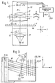
- Fig. 1 is an elevation of a first example of the apparatus.
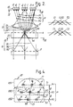
- Fig. 2 shows a part of Fig. 1 to an enlarged scale.
- Fig. 3 is a view on the line III-III in Fig. 2.
- Fig. 4 is a view on the line IV-IV in Fig. 2.
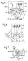
- Fig. 5 is an elevation of a second example of the apparatus.
- Fig. 6 is an elevation of a third example of the apparatus.
- Fig. 7 is a plan view of Fig. 6.
- Fig. 8 is a schematic view of a fourth example.
- Fig. 9 is a schematic view of a fifth example.
- Fig.10 is a schematic view of a sixth example.
- Fig.11 is a plan view of Fig. 10.
- light from a source 10 is collimated by a lens 15 and illuminates a scale defined by a first grating 11 provided on an elongate transparent body 16. Between the lens 15 and the first grating 11 there is arranged a second grating 12 which divides the collimated light into a periodic light pattern A.
- the light from the source 10 may be non-coherent.
- the first grating 11 diffracts the light from the pattern A into primary orders B which generate a set of fringes C at the plane A-A of a third or analyser grating 13.
- a fourth grating 14 is introduced between the first grating 11 and the third grating 13 at a given distance G from the latter grating.
- a lens 17 at the far side of the grating 13 focusses the light emerging from the grating 13 onto a system 18 of opto-electronic transducers.
- the light source 10 and the gratings 12, 13, 14 are embodied in a readhead 19 which is movable relative to the grating 11 in the direction of the length of the body 16. In operation, the movement of the readhead 19 causes the fringes C to move across the grating 13 and give rise to a sinusoidal light modulation E at the far side of the grating 13.
- the grating 11, 12, 13, 14 extend in XY planes spaced in the direction Z.
- the lines, e.g. 13A (Fig. 3) of the grating 11, 12, 13 extend in the direction Y.
- the grating 14 is a beam splitter (Fig. 2) which divides each primary order B approaching the grating 13 into a group of secondary orders D.
- Fig. 2 The grating 14 is a beam splitter (Fig. 2) which divides each primary order B approaching the grating 13 into a group of secondary orders D.
- each of three primary orders B0, B1, B2 is divided into a group comprising of three secondary orders D0, D1, D2, so that there are three such groups defining altogether nine secondary orders, each of which has its own unique direction but which are grouped in three phases P0, P1, P2. Accordingly, the fringes C occur in three phases C0, C1, C2, and the modulations E occur in three phases E0, E1, E2.
- a decollimating lens 17 is arranged to focus the nine modulated secondary orders D to respective nine foci or light signals 0-8.
- each secondary order comprises a group of rays, e.g. DR, having the same direction and which converge on to the same one, e.g. 4, of the foci 0-8.
- the lens 17 collects like order D at the respective foci 0-8. It will be clear that each focus 0-8 receives light from the whole of the region covered by the lens 17, i.e. from the whole of the region of the scale seen by the lens.
- the foci of those secondary orders which have the same phase are provided with a respective transducer of the system 18.
- the transducers 180, 181, 182 having respective output signals S0, S1, S2, collectively denoted S, corresponding to the respective phases P0, P1, P2.
- the inner signals 0, 1, 2 of the respective phases P0, P1, P2 are not modulated. However, such modulation does occur if phase gratings are used. This is described later herein.
- the gratings 13,14 are provided at opposite sides of a glass plate 20 (Fig. 2, 3) but, whereas the gratings 11, 12, 13 define spaced lines 11A, 12A, 13A respectively, all extending in the direction Y, the grating 14 defines spaced line 14A extending at an angle ⁇ to those of the other gratings thereby effecting the separation of the phases P0,P1,P2.
- the diffracting effect of the grating 14 at the angle ⁇ creates the fringes C1, C2 to opposite sides of the fringes C0 along a line B-B normal to the lines of the grating 14.
- the components C1x, C2x of this displacement in the direction normal to the lines of the grating 13 constitutes the separation of the phases P0, P1, P2.
- the grating 14 may be situated anywhere in the light path between the gratings 12, 13 but it is advantageous for the grating 14 to be situated close to the one or the another of the gratings 12,13 because then the gratings 12,14 or 13,14, as the case may be can be provided at opposite sides of the same glass plate. Also, if the gratings 12,14 or 13,14 are relatively close together, a relatively large said angle ⁇ as obtainable as will be seen from expression (1) above.
- the output signals S of the transducers 18 vary sinusoidally and have a phase difference which in this case is 120°.
- the signals S are connected to a quadrature circuit 20 being a circuit, known per se, for processing such signals with a view to obtaining an accurate sine signal 20A each cycle of which represents a relative dispacement between the readhead 19 and the grating 11 by one pitch thereof or an integer multiple of that pitch.
- the circuit 20 also produces a cosine signal 20B corresponding to the sine signal 20A and required for determining the direction of said displacement.
- An example of a circuit such as the circuit 20 is shown in our International Patent Publication No. WO 87/07943.
- the grating 11 is transmissive and the gratings are arranged for the light to interact in succession with the gratings 12, 11, 14 and 13. That is, the grating generating the periodic light pattern is first; the grating defining the scale is second and, in this case, also generates the primary diffraction orders; the grating generating the secondary order is third; and the grating generating the light modulation is last.
- the inner signals 0, 1, 2 are not modulated, i.e. they merely define a relatively steady light level.
- all the gratings 11, 12, 13, 14 are phase gratings whereby the inner signals 0, 1, 2 also become modulated.
- Such modulation may occur in antiphase with the outer signals 3,6; 4,7; and 5,8 respectively if the mark-space ratio of the phase gratings is 1:1.
- arrangement is made, in each phase, to sum the outer two signals, e.g. 5,8, and combine them in push-pull order with the inner signal, e.g. 2, whereby a good sign wave, without a DC component, is obtainable.
- the intermediate phase P0 is eliminated by suitable dimensioning of the profile of the grating 14.
- the second example, shown in Fig. 5, is equivalent to that shown in Fig. 1 in that the gratings are arranged for the light to interact in succession with the gratings 12, 11, 14 and 13.
- the example of Fig. 5 differs as follows.
- the gratings 12, 14, 13 are provided on a single plate of glass as shown and a single lens 15/17 is arranged for one half therof to collimate the light from the source 10 and for the other half thereof to decollimate the secondary orders and distribute the respective phases on to the transducers 180, 181, 182.
- the third example differs from the first and second examples in that the gratings are arranged for the light to interact in succession with the gratings 11, 12, 14 and 13 so that the above mentioned optical lever effect is not obtained.
- the grating 11 is reflective and is a blazed grating profiled to reflect the light from the source 10 into the readhead 19.
- the gratings are arranged for the light to interact in succession with the gratings 11, 14, 12, and 13.
- the gratings are arranged for the light to interact in succession with the gratings 12, 14, 11 and 13.
- the light used is coherent such as from a laser 60.
- the basic apparatus requires only two gratings, that is a grating 61 defining the scale and a grating 63 for generating the light modulation.
- One of the gratings 61 or 63 when illuminated by the laser 60, will produce the primary interference fringes in the plane of the other grating, 63 or 61.
- the lines of the gratings 61, 63 have the same direction.
- the grating for generating the phase seperation constitutes a third grating arranged between the gratings 61, 63 and having lines lying at angle to those of the gratings 61, 63 substantially as described with reference to the gratings 14, 13 of Figs. 1 to 4.
- gratings which may be referred to as a primary, a secondary and a tertiary grating and which occur in the order of the numerals 11, 14, 13 (Figs. 1 or 5) or 12, 14, 13 (Fig. 6) or 14, 12, 13 (Fig. 8) or 14, 11, 13 (Fig. 9) or 61, 64, 63 (Fig. 10).
- the primary grating 11, 12, 14, 14 or 61 generates the primary orders of diffraction B
- the primary grating and the secondary grating 14, 14, 12, 11 or 64 are angularly offset relative to each other so that phase-separated secondary orders of diffraction D are generated by the secondary grating
- the primary and secondary gratings cooperate to generate diffraction fringes C separated in phases P corresponding to those of the secondary orders
- at least one of the primary and secondary gratings is supported for movement relative to the tertiary grating 13 or 63
- the tertiary grating is positioned so that such movement is readable by detection of the light modulations generated by the corresponding relative movement between the fringes and the tertiary grating.
Landscapes
- Physics & Mathematics (AREA)
- General Physics & Mathematics (AREA)
- Optical Transform (AREA)
- Optical Filters (AREA)
- Optical Elements Other Than Lenses (AREA)
Claims (17)
erste, zweite und dritte Gittermittel (11, 12, 13), die jeweils durch eine Reihe von mit Abstand voneinander angebrachten parallelen Linien (11A, 12A, 13A) bestimmt sind, die sich im wesentlichen senkrecht zu der Meßrichtung (x) erstrecken;
eine Lichtquelle (10), die angeordnet ist, aufeinanderfolgend das erste, zweite und dritte Gittermittel (11, 12, 13) zu beleuchten;
wobei eines der Gittermittel (11, 12, 13) durch die Skala (11) gebildet ist, die anderen (12, 13) Gittermittel in dem Lesekopf (19) vorgesehen sind;
eine Relativbewegung der Skala (11) und des Lesekopfes (19) eine Lichtmodulation in Abstrahlrichtung von dem dritten Gittermittel (13) verursachen;
und Phasentrennmittel zum Auftrennen der Modulation in eine Vielzahl von Phasen, dadurch gekennzeichnet, daß:
das Phasentrennmittel einen zwischen dem ersten (11) und dem dritten (13) Gittermittel vorgesehenen Strahlenteiler (14) umfaßt.

α = der Winkel,
G = der Abstand zwischen dem optischen Gitter (14) und dem dazu nächsten ersten, zweiten oder dritten Gittermittel (11, 12, 13),
Δα = eine Herstelltoleranz für den Winkel α,
ΔG = eine Herstelltoleranz für den Abstand G ist.
eine Skala bestimmendes erstes Gittermittel (61), einen zur Versetzung relativ zur Skala (61) ausgelegten Lesekopf (19),
zweites, an dem Lesekopf (19) vorgesehenes Gittermittel (63),
eine an dem Lesekopf (19) vorgesehene Quelle (60) kohärenten Lichts zum Beleuchten eines von den ersten (61) und zweiten (63) Gittermitteln zur Erzeugung von Interferenzstreifen in der Ebene des jeweils anderen der ersten (61) und zweiten (63) Gittermittel,
wobei die Interferenzstreifen eine Bewegung relativ zu dem anderen der ersten (61) und zweiten (63) Gittermittel aufweisen entsprechend der Versetzung, um dadurch eine entsprechende Lichtmodulation zu erzeugen,
das erste und zweite Gittermittel jeweils eine durch mit Abstand voneinander vorgesehene Linien (61A, 63A) bestimmte periodische Struktur besitzen,
Phasentrennmittel zum Auftrennen der Modulation in eine Vielzahl von Phasen zur Erzeugung eines Phasenschiebe-Signals der Modulation,
dadurch gekennzeichnet, daß:
ein optisches Gitter (64) zwischen das erste und das zweite Gittermittel eingesetzt ist,
die jeweiligen Linien des ersten und des zweiten Gittermittels in einer gemeinsamen Richtung liegen, und
das optisches Gitter (64) bestimmt ist durch mit einem Winkel zu der gemeinsamen Richtung liegende Linien (64A), um dadurch die Phasen-Trennung zu bewirken.
die Vorrichtung Mittel zum Sammeln gleicher Ordnungen der Reihen von sekundären Ordnungen umfaßt und
Mittel zum Erfassen der gesammelten gleichen Ordnungen.
Applications Claiming Priority (2)
| Application Number | Priority Date | Filing Date | Title |
|---|---|---|---|
| GB8729066 | 1987-12-12 | ||
| GB878729066A GB8729066D0 (en) | 1987-12-12 | 1987-12-12 | Opto-electronic scale-reading apparatus |
Publications (2)
| Publication Number | Publication Date |
|---|---|
| EP0344281A1 EP0344281A1 (de) | 1989-12-06 |
| EP0344281B1 true EP0344281B1 (de) | 1992-04-15 |
Family
ID=10628423
Family Applications (1)
| Application Number | Title | Priority Date | Filing Date |
|---|---|---|---|
| EP19890900622 Expired EP0344281B1 (de) | 1987-12-12 | 1988-12-12 | Opto-elektronischer skalenlese-apparat |
Country Status (5)
| Country | Link |
|---|---|
| EP (1) | EP0344281B1 (de) |
| JP (1) | JPH02502673A (de) |
| DE (1) | DE3870229D1 (de) |
| GB (1) | GB8729066D0 (de) |
| WO (1) | WO1989005440A1 (de) |
Families Citing this family (9)
| Publication number | Priority date | Publication date | Assignee | Title |
|---|---|---|---|---|
| US5064290A (en) * | 1987-12-12 | 1991-11-12 | Renishaw Plc | Opto-electronic scale-reading apparatus wherein phase-separated secondary orders of diffraction are generated |
| JPH03505633A (ja) * | 1989-04-15 | 1991-12-05 | レニショウ パブリック リミテッド カンパニー | 光電スケール読取装置 |
| WO1991003712A1 (en) * | 1989-09-06 | 1991-03-21 | Human Machine Interfaces Ltd. | Measurement device |
| GB9023659D0 (en) * | 1990-10-31 | 1990-12-12 | Renishaw Plc | Opto-electronic scale reading apparatus |
| JP2862417B2 (ja) * | 1990-11-16 | 1999-03-03 | キヤノン株式会社 | 変位測定装置及び方法 |
| EP0486050B1 (de) * | 1990-11-16 | 1998-02-04 | Canon Kabushiki Kaisha | Verfahren und Vorrichtung zum Messen von Verschiebungen |
| GB9425907D0 (en) * | 1994-12-22 | 1995-02-22 | Renishaw Plc | Opto-electronic scale reading apparatus |
| DE19614466B4 (de) * | 1996-04-12 | 2012-02-02 | Dr. Johannes Heidenhain Gmbh | Signalverarbeitungsanordnung für eine Positionsmeßeinrichtung |
| US7161139B2 (en) | 2001-09-04 | 2007-01-09 | Dr. Johannes Heidenhain Gmbh | Position-measuring system and method for operating a position-measuring system |
Family Cites Families (2)
| Publication number | Priority date | Publication date | Assignee | Title |
|---|---|---|---|---|
| JPS6023282B2 (ja) * | 1974-03-15 | 1985-06-06 | ナシヨナル・リサーチ・デイベロツプメント・コーポレイシヨン | 相対変位測定装置 |
| DE2451994A1 (de) * | 1974-11-02 | 1976-11-04 | Fromund Prof Dipl Phys Hock | Verfahren und anordnung zur erzeugung photoelektrischer signale |
-
1987
- 1987-12-12 GB GB878729066A patent/GB8729066D0/en active Pending
-
1988
- 1988-12-12 EP EP19890900622 patent/EP0344281B1/de not_active Expired
- 1988-12-12 WO PCT/GB1988/001081 patent/WO1989005440A1/en not_active Ceased
- 1988-12-12 DE DE8989900622T patent/DE3870229D1/de not_active Expired - Fee Related
- 1988-12-12 JP JP1500397A patent/JPH02502673A/ja active Pending
Also Published As
| Publication number | Publication date |
|---|---|
| EP0344281A1 (de) | 1989-12-06 |
| WO1989005440A1 (en) | 1989-06-15 |
| DE3870229D1 (de) | 1992-05-21 |
| GB8729066D0 (en) | 1988-01-27 |
| JPH02502673A (ja) | 1990-08-23 |
Similar Documents
| Publication | Publication Date | Title |
|---|---|---|
| US5064290A (en) | Opto-electronic scale-reading apparatus wherein phase-separated secondary orders of diffraction are generated | |
| US4943716A (en) | Diffraction-type optical encoder with improved detection signal insensitivity to optical grating gap variations | |
| EP2607858B1 (de) | Optischer Kodierer mit anpassbarer Auflösung | |
| US9080899B2 (en) | Optical displacement encoder having plural scale grating portions with spatial phase offset of scale pitch | |
| US9029757B2 (en) | Illumination portion for an adaptable resolution optical encoder | |
| EP1435510A1 (de) | Optischer Kodierer mit Interferenzgitter | |
| US4975571A (en) | Opto-electronic scale-reading apparatus | |
| JPH0131127B2 (de) | ||
| EP2082118B1 (de) | Interferometrischer optischer positionskodierer mit räumlicher filterung von beugungsordnungen für verbesserte genauigkeit | |
| JPH0697171B2 (ja) | 変位測定装置 | |
| EP2169358A2 (de) | Verschiebungsmessvorrichtung | |
| EP0344281A1 (de) | Opto-elektronischer skalenlese-apparat | |
| EP2743651A2 (de) | Beleuchtungsabschnitt für einen optischen Codierer mit anpassbarer Auflösung | |
| JP3641316B2 (ja) | 光学式エンコーダ | |
| JP2005147828A (ja) | 変位検出装置 | |
| EP1795873B1 (de) | Fotoelektrischer Kodierer | |
| EP0344291A1 (de) | Opto-elektronischer skalenlese-apparat. | |
| US4879462A (en) | Opto-electronic scale-reading apparatus having spatial filter for wavelength separation | |
| JP2503561B2 (ja) | レ―ザ―干渉式エンコ―ダ | |
| EP2743650B1 (de) | Beleuchtungsabschnitt für einen optischen Codierer mit anpassbarer Auflösung | |
| WO1990013006A1 (en) | Opto-electronic scale-reading apparatus | |
| JP2718439B2 (ja) | 測長または測角装置 | |
| GB2246430A (en) | Optical encoder | |
| JP7532176B2 (ja) | 光学式エンコーダ及び制御装置 | |
| JPS6110716A (ja) | 光電式エンコ−ダ |
Legal Events
| Date | Code | Title | Description |
|---|---|---|---|
| PUAI | Public reference made under article 153(3) epc to a published international application that has entered the european phase |
Free format text: ORIGINAL CODE: 0009012 |
|
| 17P | Request for examination filed |
Effective date: 19890719 |
|
| AK | Designated contracting states |
Kind code of ref document: A1 Designated state(s): CH DE FR GB IT LI SE |
|
| RAP3 | Party data changed (applicant data changed or rights of an application transferred) |
Owner name: RENISHAW PLC |
|
| 17Q | First examination report despatched |
Effective date: 19910124 |
|
| GRAA | (expected) grant |
Free format text: ORIGINAL CODE: 0009210 |
|
| ITF | It: translation for a ep patent filed | ||
| AK | Designated contracting states |
Kind code of ref document: B1 Designated state(s): CH DE FR GB IT LI SE |
|
| REF | Corresponds to: |
Ref document number: 3870229 Country of ref document: DE Date of ref document: 19920521 |
|
| ET | Fr: translation filed | ||
| PGFP | Annual fee paid to national office [announced via postgrant information from national office to epo] |
Ref country code: FR Payment date: 19921111 Year of fee payment: 5 |
|
| PG25 | Lapsed in a contracting state [announced via postgrant information from national office to epo] |
Ref country code: SE Effective date: 19921213 |
|
| PG25 | Lapsed in a contracting state [announced via postgrant information from national office to epo] |
Ref country code: LI Effective date: 19921231 Ref country code: CH Effective date: 19921231 |
|
| PLBE | No opposition filed within time limit |
Free format text: ORIGINAL CODE: 0009261 |
|
| STAA | Information on the status of an ep patent application or granted ep patent |
Free format text: STATUS: NO OPPOSITION FILED WITHIN TIME LIMIT |
|
| 26N | No opposition filed | ||
| REG | Reference to a national code |
Ref country code: CH Ref legal event code: PL |
|
| PG25 | Lapsed in a contracting state [announced via postgrant information from national office to epo] |
Ref country code: FR Effective date: 19940831 |
|
| REG | Reference to a national code |
Ref country code: FR Ref legal event code: ST |
|
| EUG | Se: european patent has lapsed |
Ref document number: 89900622.5 Effective date: 19930709 |
|
| PGFP | Annual fee paid to national office [announced via postgrant information from national office to epo] |
Ref country code: GB Payment date: 19951121 Year of fee payment: 8 |
|
| PGFP | Annual fee paid to national office [announced via postgrant information from national office to epo] |
Ref country code: DE Payment date: 19951122 Year of fee payment: 8 |
|
| PG25 | Lapsed in a contracting state [announced via postgrant information from national office to epo] |
Ref country code: GB Effective date: 19961212 |
|
| GBPC | Gb: european patent ceased through non-payment of renewal fee |
Effective date: 19961212 |
|
| PG25 | Lapsed in a contracting state [announced via postgrant information from national office to epo] |
Ref country code: DE Effective date: 19970902 |
|
| PG25 | Lapsed in a contracting state [announced via postgrant information from national office to epo] |
Ref country code: IT Free format text: LAPSE BECAUSE OF NON-PAYMENT OF DUE FEES;WARNING: LAPSES OF ITALIAN PATENTS WITH EFFECTIVE DATE BEFORE 2007 MAY HAVE OCCURRED AT ANY TIME BEFORE 2007. THE CORRECT EFFECTIVE DATE MAY BE DIFFERENT FROM THE ONE RECORDED. Effective date: 20051212 |