EP0343749B1 - Container made of thermoplastic material - Google Patents
Container made of thermoplastic material Download PDFInfo
- Publication number
- EP0343749B1 EP0343749B1 EP19890201320 EP89201320A EP0343749B1 EP 0343749 B1 EP0343749 B1 EP 0343749B1 EP 19890201320 EP19890201320 EP 19890201320 EP 89201320 A EP89201320 A EP 89201320A EP 0343749 B1 EP0343749 B1 EP 0343749B1
- Authority
- EP
- European Patent Office
- Prior art keywords
- end wall
- weld
- face
- edge
- flange
- Prior art date
- Legal status (The legal status is an assumption and is not a legal conclusion. Google has not performed a legal analysis and makes no representation as to the accuracy of the status listed.)
- Expired - Lifetime
Links
- 239000012815 thermoplastic material Substances 0.000 title claims description 5
- 238000003466 welding Methods 0.000 claims description 15
- 238000004519 manufacturing process Methods 0.000 claims description 5
- 238000010438 heat treatment Methods 0.000 claims description 4
- 239000000463 material Substances 0.000 description 10
- 239000004033 plastic Substances 0.000 description 6
- 239000011324 bead Substances 0.000 description 5
- 230000007704 transition Effects 0.000 description 5
- 239000007788 liquid Substances 0.000 description 4
- 238000001746 injection moulding Methods 0.000 description 3
- 238000003801 milling Methods 0.000 description 3
- 230000002411 adverse Effects 0.000 description 1
- 238000001816 cooling Methods 0.000 description 1
- 238000006073 displacement reaction Methods 0.000 description 1
- 238000001125 extrusion Methods 0.000 description 1
- 238000002347 injection Methods 0.000 description 1
- 239000007924 injection Substances 0.000 description 1
- 238000000034 method Methods 0.000 description 1
- 230000000717 retained effect Effects 0.000 description 1
- 238000009827 uniform distribution Methods 0.000 description 1
Images


Classifications
-
- B—PERFORMING OPERATIONS; TRANSPORTING
- B29—WORKING OF PLASTICS; WORKING OF SUBSTANCES IN A PLASTIC STATE IN GENERAL
- B29C—SHAPING OR JOINING OF PLASTICS; SHAPING OF MATERIAL IN A PLASTIC STATE, NOT OTHERWISE PROVIDED FOR; AFTER-TREATMENT OF THE SHAPED PRODUCTS, e.g. REPAIRING
- B29C65/00—Joining or sealing of preformed parts, e.g. welding of plastics materials; Apparatus therefor
- B29C65/02—Joining or sealing of preformed parts, e.g. welding of plastics materials; Apparatus therefor by heating, with or without pressure
- B29C65/18—Joining or sealing of preformed parts, e.g. welding of plastics materials; Apparatus therefor by heating, with or without pressure using heated tools
- B29C65/20—Joining or sealing of preformed parts, e.g. welding of plastics materials; Apparatus therefor by heating, with or without pressure using heated tools with direct contact, e.g. using "mirror"
-
- B—PERFORMING OPERATIONS; TRANSPORTING
- B29—WORKING OF PLASTICS; WORKING OF SUBSTANCES IN A PLASTIC STATE IN GENERAL
- B29C—SHAPING OR JOINING OF PLASTICS; SHAPING OF MATERIAL IN A PLASTIC STATE, NOT OTHERWISE PROVIDED FOR; AFTER-TREATMENT OF THE SHAPED PRODUCTS, e.g. REPAIRING
- B29C66/00—General aspects of processes or apparatus for joining preformed parts
- B29C66/50—General aspects of joining tubular articles; General aspects of joining long products, i.e. bars or profiled elements; General aspects of joining single elements to tubular articles, hollow articles or bars; General aspects of joining several hollow-preforms to form hollow or tubular articles
- B29C66/51—Joining tubular articles, profiled elements or bars; Joining single elements to tubular articles, hollow articles or bars; Joining several hollow-preforms to form hollow or tubular articles
- B29C66/54—Joining several hollow-preforms, e.g. half-shells, to form hollow articles, e.g. for making balls, containers; Joining several hollow-preforms, e.g. half-cylinders, to form tubular articles
- B29C66/542—Joining several hollow-preforms, e.g. half-shells, to form hollow articles, e.g. for making balls, containers; Joining several hollow-preforms, e.g. half-cylinders, to form tubular articles joining hollow covers or hollow bottoms to open ends of container bodies
-
- B—PERFORMING OPERATIONS; TRANSPORTING
- B29—WORKING OF PLASTICS; WORKING OF SUBSTANCES IN A PLASTIC STATE IN GENERAL
- B29C—SHAPING OR JOINING OF PLASTICS; SHAPING OF MATERIAL IN A PLASTIC STATE, NOT OTHERWISE PROVIDED FOR; AFTER-TREATMENT OF THE SHAPED PRODUCTS, e.g. REPAIRING
- B29C66/00—General aspects of processes or apparatus for joining preformed parts
- B29C66/50—General aspects of joining tubular articles; General aspects of joining long products, i.e. bars or profiled elements; General aspects of joining single elements to tubular articles, hollow articles or bars; General aspects of joining several hollow-preforms to form hollow or tubular articles
- B29C66/51—Joining tubular articles, profiled elements or bars; Joining single elements to tubular articles, hollow articles or bars; Joining several hollow-preforms to form hollow or tubular articles
- B29C66/54—Joining several hollow-preforms, e.g. half-shells, to form hollow articles, e.g. for making balls, containers; Joining several hollow-preforms, e.g. half-cylinders, to form tubular articles
- B29C66/545—Joining several hollow-preforms, e.g. half-shells, to form hollow articles, e.g. for making balls, containers; Joining several hollow-preforms, e.g. half-cylinders, to form tubular articles one hollow-preform being placed inside the other
-
- B—PERFORMING OPERATIONS; TRANSPORTING
- B65—CONVEYING; PACKING; STORING; HANDLING THIN OR FILAMENTARY MATERIAL
- B65D—CONTAINERS FOR STORAGE OR TRANSPORT OF ARTICLES OR MATERIALS, e.g. BAGS, BARRELS, BOTTLES, BOXES, CANS, CARTONS, CRATES, DRUMS, JARS, TANKS, HOPPERS, FORWARDING CONTAINERS; ACCESSORIES, CLOSURES, OR FITTINGS THEREFOR; PACKAGING ELEMENTS; PACKAGES
- B65D11/00—Containers having bodies formed by interconnecting or uniting two or more rigid, or substantially rigid, components made wholly or mainly of plastics material
- B65D11/20—Details of walls made of plastics material
-
- B—PERFORMING OPERATIONS; TRANSPORTING
- B29—WORKING OF PLASTICS; WORKING OF SUBSTANCES IN A PLASTIC STATE IN GENERAL
- B29C—SHAPING OR JOINING OF PLASTICS; SHAPING OF MATERIAL IN A PLASTIC STATE, NOT OTHERWISE PROVIDED FOR; AFTER-TREATMENT OF THE SHAPED PRODUCTS, e.g. REPAIRING
- B29C66/00—General aspects of processes or apparatus for joining preformed parts
- B29C66/01—General aspects dealing with the joint area or with the area to be joined
- B29C66/05—Particular design of joint configurations
- B29C66/10—Particular design of joint configurations particular design of the joint cross-sections
- B29C66/11—Joint cross-sections comprising a single joint-segment, i.e. one of the parts to be joined comprising a single joint-segment in the joint cross-section
- B29C66/112—Single lapped joints
-
- B—PERFORMING OPERATIONS; TRANSPORTING
- B29—WORKING OF PLASTICS; WORKING OF SUBSTANCES IN A PLASTIC STATE IN GENERAL
- B29C—SHAPING OR JOINING OF PLASTICS; SHAPING OF MATERIAL IN A PLASTIC STATE, NOT OTHERWISE PROVIDED FOR; AFTER-TREATMENT OF THE SHAPED PRODUCTS, e.g. REPAIRING
- B29C66/00—General aspects of processes or apparatus for joining preformed parts
- B29C66/01—General aspects dealing with the joint area or with the area to be joined
- B29C66/05—Particular design of joint configurations
- B29C66/10—Particular design of joint configurations particular design of the joint cross-sections
- B29C66/11—Joint cross-sections comprising a single joint-segment, i.e. one of the parts to be joined comprising a single joint-segment in the joint cross-section
- B29C66/114—Single butt joints
-
- B—PERFORMING OPERATIONS; TRANSPORTING
- B29—WORKING OF PLASTICS; WORKING OF SUBSTANCES IN A PLASTIC STATE IN GENERAL
- B29C—SHAPING OR JOINING OF PLASTICS; SHAPING OF MATERIAL IN A PLASTIC STATE, NOT OTHERWISE PROVIDED FOR; AFTER-TREATMENT OF THE SHAPED PRODUCTS, e.g. REPAIRING
- B29C66/00—General aspects of processes or apparatus for joining preformed parts
- B29C66/80—General aspects of machine operations or constructions and parts thereof
- B29C66/83—General aspects of machine operations or constructions and parts thereof characterised by the movement of the joining or pressing tools
- B29C66/832—Reciprocating joining or pressing tools
-
- B—PERFORMING OPERATIONS; TRANSPORTING
- B29—WORKING OF PLASTICS; WORKING OF SUBSTANCES IN A PLASTIC STATE IN GENERAL
- B29L—INDEXING SCHEME ASSOCIATED WITH SUBCLASS B29C, RELATING TO PARTICULAR ARTICLES
- B29L2031/00—Other particular articles
- B29L2031/712—Containers; Packaging elements or accessories, Packages
- B29L2031/7154—Barrels, drums, tuns, vats
-
- Y—GENERAL TAGGING OF NEW TECHNOLOGICAL DEVELOPMENTS; GENERAL TAGGING OF CROSS-SECTIONAL TECHNOLOGIES SPANNING OVER SEVERAL SECTIONS OF THE IPC; TECHNICAL SUBJECTS COVERED BY FORMER USPC CROSS-REFERENCE ART COLLECTIONS [XRACs] AND DIGESTS
- Y10—TECHNICAL SUBJECTS COVERED BY FORMER USPC
- Y10S—TECHNICAL SUBJECTS COVERED BY FORMER USPC CROSS-REFERENCE ART COLLECTIONS [XRACs] AND DIGESTS
- Y10S220/00—Receptacles
- Y10S220/29—Welded seam
Definitions
- the invention relates to a container, comprising a body, made of thermoplastic material, and end walls, at least one of which is made of a thermoplastic material, said body and end wall being butt-welded to each other with flat weld faces lying at right angles to the axis of the body, the weld face of the body being of a width which prior to welding is essentially equal to the wall thickness of the body, while the weld face of the end wall is of a width which is greater than the width of the weld face of the body and has an external diameter which is greater than the external diameter of the body, and said end wall has an axially and radially outward-facing flange which forms a gripping edge.
- Such a container is known from EP-A-0 210 679.
- the body and one or both end walls are welded to each other by means of so-called heated-tool welding, i.e. welding in which the faces to be welded to each other are brought to welding temperature by means of a hot plate, the heated tool, following which the plate is removed and the two heated weld faces are pressed together and fused.
- the heated tool is a plate which is flat on both sides. Only those faces of body and end wall which are to be welded to each other may be brought into contact with this tool. In the case of the body this is no problem, because it is a continuous cylindrical tube.
- the end wall is more complex in shape, in particular due to the fact that there must be a gripping edge which make it possible to take hold of the container, not only by hand, but in particular with a gripping device designed for the purpose, which can grip the gripping edge at two opposite faces.
- a gripping device designed for the purpose, which can grip the gripping edge at two opposite faces.
- the gripping edge and the place where the material passes from the gripping edge to the end wall must be sturdy.
- the gripper must not grip the weld point. All this means that in the case of the known container the weld face of the end wall is located inwards from the innermost face of the gripping edge, viewed in the axial direction.
- the transition from an end wall to the gripping edge, situated near the weld point, has a large volume of material. This volume is at the end of the flow path of the liquid plastic in the injection mould.
- the stream of liquid plastic has to divide during injection moulding into a stream going to the hollow for the gripping edge and a stream going to the part which forms the weld face of the end wall after setting of the plastic.
- the face which is going to form the weld face is an end face for the flow front.
- This known container is of excellent quality and meets all the international strength and safety standards laid down by law, but it does have a number of disadvantages and, if they could be eliminated, an even better container would be produced.
- the welded seam is ugly, while the bottom gripper can glance off the weld and then no longer properly grips the face intended for the gripper.
- the concentricity of cover and body can have a slight deviation of about 1.5 mm, but the consequence of this is that the weld face of the end wall has to be wider than the weld face of the body, for locally the body can be fused more inwards or more outwards with the weld face of the end wall.
- the object of the invention is then to produce a container in which the weld seam can no longer be a problem and no longer needs milling away, while the welding time can be reduced further.
- the outside edge of the end wall has an axially extending edge bounding the weld face of the end wall on the outside and overlapping the weld, and the axial thickness of the end wall at the point of the weld is essentially equal to or slightly greater than the radial thickness of the axially extending edge or the thickness of the end wall.
- This axially extending edge conceals the weld from view and takes it outside the working range of a gripper when it has to grip the projecting edge.
- the stream of liquid plastic is now no longer divided near the weld face and it no longer forms an end face against which the stream runs.
- Shape inaccuracies can be avoided partly due to the fact that the edge part of the end wall is given a material thickness which at the site of the weld and outwards from the weld is the same as the material thickness of the end wall itself and in any case is not greater than 20% more than the thickness of the end wall, as a result of which the welding time can be reduced further and can be less than the previously achieved welding time of 2 minutes.
- the production time of the end wall is also shorter.
- the axially extending edge overlapping the weld in the axial direction will form the bottom face of the flange, while the axial distance between said bottom face and the bottom of the groove is greater than the axial distance between said bottom and the weld face, and the latter axial distance is the axial distance from the end wall, which is essentially equal to or slightly greater than the radial thickness of the flange, and thus of the axially projecting edge or the thickness of the end wall.
- the gripping edge and the axially projecting edge overlapping the weld are then integrated to a flange which is thus at the weld, as in the case of the known container, but is displaced in the axial direction, so that the weld and the bottom of the V-shaped groove have come closer together.
- the distance between the two opposite faces of the gripping edge, on which faces the grippers grip it is necessary for the distance between the two opposite faces of the gripping edge, on which faces the grippers grip, to be essentially the same distance as that in the known container. These are thus the bottom face of the flange and the bottom of the groove.
- the central part of the end wall is at an axial distance from the plane through the weld point which is equal to that of the known container.
- This end wall is in the shape of a bowl with a flat bottom, diverging walls and an edge which is outwardly provided with a flange. This shape is desirable for the required resistance of the container to stresses occurring, such as impact stresses.
- the dimensions of the gripping edge are also defined, by the gripper gripping them as explained above.
- the container according to the invention thus essentially differs from the known container, at least in the embodiment in which the gripping edge is at the position of the weld, in that the flange is displaced axially inwards, so that weld face and bottom of the V-shaped groove have come closer to each other.
- the invention can thus also be seen in the method of production of the end wall and thus the production of a container.
- the invention also relates to a device for the production of a container, said device in the existing embodiment being characterized by means for clamping an end wall, means for clamping a body, and a heatable plate which can be placed between the body and the end wall to be welded to each other, and with which the faces to be welded to each other are heated and then pressed onto each other after removal of the heated plate, said device according to the invention being characterized in that the plate at the side facing the end wall is provided with a circular rib which projects beyond the plane of the plate, and of which the external face standing at right angles to the longitudinal axis of the circular plate forms the face for heating of the weld face of the end wall, while the external diameter thereof is smaller than the diameter of the axially projecting edge of the outside edge of the end wall of the container.
- the flat heated plate is thus replaced by a plate which is flat at the side facing the body, as in the known device, but which at the side facing the end wall has a rib which with its outside edge fits inside the axially projecting edge, and with which the weld face of the end wall can thus be heated.
- Fig. 1 shows in cross section the known welded joint of a container.
- Fig. 2 shows in the same way as in Fig. 1 the welded joint of a container according to the invention.
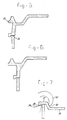
- Fig. 3 shows a variant of the container design according to the invention.
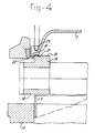
- Fig. 4 shows schematically in cross section how the device for producing the welded joint works.
- Figs. 5, 6 and 7 show various design variants of the container according to the invention.
- Fig. 1 shows a container body 1 obtained by extrusion and an end wall 2 produced by injection moulding.
- This end wall 2 has at the outside edge a flange 3 which passes via a V-shaped groove 4 into the part of the end wall which slants upwards and is indicated by 5, said groove 4 together with the bottom face 6 forming the gripping edge.
- This edge part of the end wall has a rib 7 with a weld face 8 for welding thereto the end edge of the body 1.
- the welded joint is indicated by the welding beads 9.
- the bottom face 6 of the flange 3 has a width "c1" and the weld face has a width "d1", which is greater than the thickness of the body 1.
- Fig. 2 shows the embodiment according to the invention.
- the body is indicated again by 1 and the end wall by 2′, the side part being indicated by 5′.
- the flange is indicated by 3′ and again forms the V-shaped groove 4′ with the side part 5′.
- the flange 3′ the height or axial dimension of which is equal to that of Fig. 1 is, however, axially displaced here, and thus forms the axially extending part 10 overlapping the weld face 8′. While in the case of the known joint shown in Fig. 1 part of the rib 7 also often has to be milled away during the milling away of the welding bead 9, in the embodiment according to the invention this is no longer necessary and is not possible either. The outermost welding bead 9′ is totally concealed from view.
- the width of the weld face 8′ is indicated by "d2", and the latter is greater than "d1", in order to be able to make allowances for the out-of-roundness of the body and the room needed for the weld groove.
- Fig. 3 shows another embodiment of the end wall.
- the body here is also indicated by number 1, but the end wall 11 with the slanting side wall part 12 merges at the welded joint 13 via a short horizontal part 14 into an edge 15, which projects axially over the weld 13.
- the gripping edge or flange 16 is now at the same level as the transition between the horizontal part 11 of the end wall and the slanting part 12.
- the weld is also concealed from view in this embodiment.
- the gripper now no longer engages with the edge 15, but with the flange 16, and during injection moulding this flange 16 cannot give any problems which are of importance for the welded joint, because there is no welded joint at that point, and the filling with liquid plastic is ensured by the thrust resistance which the flow undergoes in the branch relating to the slanting wall part 12. No additional quantity of material is present at the weld, so that shape irregularities do not occur there.
- Fig. 4 shows schematically the device for producing a container according to the invention.
- the body is indicated by 1 and is clamped in a body clamp 17.
- the heated plate has a heated plate surface 18 for heating the weld face of the body, and has at the opposite side a circular rib 19 which has a rectangular section and with the face 20 forms the face which serves for heating of the weld face 21 of the end wall 2.
- the rib has an external diameter which is smaller than the internal diameter of the projecting edge 10, so that the weld face 21 can be heated using the face 20.
- the end wall 2 is held fast here by the grippers 22, which engage with the bottom edge of the flange 3, and by supports 23 engaging in the V-shaped groove.
- the heated plate is removed, and the weld faces are pressed onto each other.
- Fig. 5 shows an embodiment which is essentially the same as Fig. 3 at the welded joint 24. Only the gripping edge 25 is differently shaped.
- the end wall forms a recessed part 26, which with a flanged edge 27 grips over the end edge of the body and is welded fast.
- the bottom edge 28 of the edge 27 forms one face for the gripper 29, and the inner face 30 forms the engagement face for the other gripper 31.
- the flow of melt is not divided at the weld face, the weld face is not an end face for the flow of melt, and the weld is not adversely affected and contributes to the external appearance and strength.
Landscapes
- Engineering & Computer Science (AREA)
- Mechanical Engineering (AREA)
- Lining Or Joining Of Plastics Or The Like (AREA)
- Rigid Containers With Two Or More Constituent Elements (AREA)
- Containers Having Bodies Formed In One Piece (AREA)
Applications Claiming Priority (2)
| Application Number | Priority Date | Filing Date | Title |
|---|---|---|---|
| NL8801370 | 1988-05-27 | ||
| NL8801370A NL8801370A (nl) | 1988-05-27 | 1988-05-27 | Vat uit thermoplastisch materiaal. |
Publications (2)
| Publication Number | Publication Date |
|---|---|
| EP0343749A1 EP0343749A1 (en) | 1989-11-29 |
| EP0343749B1 true EP0343749B1 (en) | 1993-01-07 |
Family
ID=19852368
Family Applications (1)
| Application Number | Title | Priority Date | Filing Date |
|---|---|---|---|
| EP19890201320 Expired - Lifetime EP0343749B1 (en) | 1988-05-27 | 1989-05-22 | Container made of thermoplastic material |
Country Status (11)
| Country | Link |
|---|---|
| US (1) | US4962862A (ja) |
| EP (1) | EP0343749B1 (ja) |
| JP (1) | JP2548374B2 (ja) |
| AU (1) | AU612262B2 (ja) |
| BR (1) | BR8902415A (ja) |
| CA (1) | CA1316657C (ja) |
| DE (1) | DE68904243T2 (ja) |
| ES (1) | ES2036792T3 (ja) |
| MX (1) | MX169859B (ja) |
| NL (1) | NL8801370A (ja) |
| ZA (1) | ZA894019B (ja) |
Families Citing this family (10)
| Publication number | Priority date | Publication date | Assignee | Title |
|---|---|---|---|---|
| JP3294647B2 (ja) * | 1991-12-13 | 2002-06-24 | ヘキスト・アクチェンゲゼルシャフト | L−ホスフィノトリシンおよびその誘導体の製造方法 |
| DE4242370C1 (de) * | 1992-12-16 | 1994-05-11 | Schuetz Werke Gmbh Co Kg | Mehrwegfaß aus Kunststoff und Verfahren zu dessen Herstellung |
| NL9301856A (nl) * | 1993-10-27 | 1995-05-16 | Leer Koninklijke Emballage | Houder uit kunststofmateriaal. |
| US5593059A (en) * | 1995-05-31 | 1997-01-14 | Neilson; Kirsten L. | Protective newspaper delivery receptable |
| US6358343B1 (en) | 1999-12-22 | 2002-03-19 | C. Winfield Scott | Method for manufacturing plastic drums |
| US6860398B2 (en) | 2000-11-30 | 2005-03-01 | Visteon Global Technologies, Inc. | Low permeation fittings, low permeation containers utilizing same, and methods for forming same |
| FR2836897B1 (fr) * | 2002-03-06 | 2004-06-25 | Jacques Gerbron | Conditionnement comportant un contenant deformable par pression et procede de fabrication |
| US6722521B2 (en) | 2002-05-07 | 2004-04-20 | Visteon Global Technologies, Inc. | Low permeation pinchoff connection for bridging a barrier layer and method of making same |
| JP2010137907A (ja) * | 2008-12-15 | 2010-06-24 | Masayuki Teshima | 飲料缶 |
| US11623411B2 (en) * | 2020-08-18 | 2023-04-11 | HCT Group Holdings Limited | Cosmetic containers and methods of manufacture |
Family Cites Families (7)
| Publication number | Priority date | Publication date | Assignee | Title |
|---|---|---|---|---|
| FR1476700A (fr) * | 1966-02-16 | 1967-04-14 | Quercia Flaminaire Sa | Perfectionnements apportés aux flacons de multirecharge d'un gaz liquéfié sous pression |
| US3434644A (en) * | 1966-09-01 | 1969-03-25 | Phillips Petroleum Co | Container |
| DE3071740D1 (en) * | 1979-10-22 | 1986-10-09 | Hardigg Ind Inc | Battery jar cover system |
| US4762249A (en) * | 1981-02-13 | 1988-08-09 | Packaging Resources Incorporated | Thermoplastic container end for inertial spinwelding of thermoplastic container ends |
| US4402461A (en) * | 1981-07-01 | 1983-09-06 | Liquipak International Inc. | Fluid-handling apparatus |
| NL8502035A (nl) * | 1985-07-15 | 1987-02-02 | Leer Koninklijke Emballage | Werkwijze en inrichting voor het door stomp-spiegel-lassen met elkaar verbinden van een door extrusie verkregen vatromp met vatdeksel. |
| US4579242A (en) * | 1985-07-29 | 1986-04-01 | Kinetico, Inc. | Molded plastic pressure tank |
-
1988
- 1988-05-27 NL NL8801370A patent/NL8801370A/nl not_active Application Discontinuation
-
1989
- 1989-05-18 US US07/353,458 patent/US4962862A/en not_active Expired - Lifetime
- 1989-05-22 ES ES89201320T patent/ES2036792T3/es not_active Expired - Lifetime
- 1989-05-22 EP EP19890201320 patent/EP0343749B1/en not_active Expired - Lifetime
- 1989-05-22 DE DE8989201320T patent/DE68904243T2/de not_active Expired - Fee Related
- 1989-05-23 CA CA 600346 patent/CA1316657C/en not_active Expired - Fee Related
- 1989-05-26 MX MX016201A patent/MX169859B/es unknown
- 1989-05-26 BR BR8902415A patent/BR8902415A/pt not_active IP Right Cessation
- 1989-05-26 ZA ZA894019A patent/ZA894019B/xx unknown
- 1989-05-26 AU AU35243/89A patent/AU612262B2/en not_active Ceased
- 1989-05-26 JP JP1134490A patent/JP2548374B2/ja not_active Expired - Lifetime
Also Published As
| Publication number | Publication date |
|---|---|
| ES2036792T3 (es) | 1993-06-01 |
| MX169859B (es) | 1993-07-28 |
| ZA894019B (en) | 1990-02-28 |
| NL8801370A (nl) | 1989-12-18 |
| DE68904243D1 (en) | 1993-02-18 |
| CA1316657C (en) | 1993-04-27 |
| AU612262B2 (en) | 1991-07-04 |
| BR8902415A (pt) | 1990-01-16 |
| JP2548374B2 (ja) | 1996-10-30 |
| JPH0263723A (ja) | 1990-03-05 |
| AU3524389A (en) | 1989-11-30 |
| EP0343749A1 (en) | 1989-11-29 |
| US4962862A (en) | 1990-10-16 |
| DE68904243T2 (de) | 1993-06-09 |
Similar Documents
| Publication | Publication Date | Title |
|---|---|---|
| US4664284A (en) | Container of tubular form | |
| EP0343749B1 (en) | Container made of thermoplastic material | |
| KR100354586B1 (ko) | 인서트 몰딩된 개방 흔적이 남는 유출구 | |
| EP1182144B1 (en) | Fitment for spouted pouch | |
| US4345692A (en) | Closure cap for a container | |
| US4342799A (en) | Hollow bodies and their manufacture | |
| US5897823A (en) | Method of forming a plastic container component and the plastic container component formed by the method | |
| US4021524A (en) | Method of making a collapsible tube with an integral cap | |
| EP1980499A2 (en) | Plastic spout | |
| GB2171046A (en) | Containers | |
| US4531930A (en) | Process for the preparation of a paper container equipped with a reinforcing ring, and a reinforcing ring for such process | |
| AU2002330343A1 (en) | Method for sealing a plastic spout | |
| NO176907B (no) | Ventilutrustet trykkbeholder av plast | |
| EP1560697B1 (en) | Bag-making method | |
| JP2008524014A (ja) | 少なくとも1つの溶着部を含む多層中空本体の製造方法 | |
| US6395215B1 (en) | Method of producing a plastic component and fuel tank for a motor vehicle | |
| AU730094B2 (en) | Process for the production of packaging tubes | |
| US3885300A (en) | Method of making a panel corner | |
| JPH05132062A (ja) | 高遮断プラスチツク容器 | |
| US6846443B1 (en) | Method for forming an improved container | |
| JP2713533B2 (ja) | 管状端を有する熱可塑性樹脂成形品の突き合せ融着方法 | |
| JPS597671Y2 (ja) | 管継手 | |
| JPH0356659B2 (ja) | ||
| JPH05272686A (ja) | 曲り管継手の射出成形方法及び装置 | |
| JP2002086497A (ja) | 樹脂サービスティー継手の成形方法 |
Legal Events
| Date | Code | Title | Description |
|---|---|---|---|
| PUAI | Public reference made under article 153(3) epc to a published international application that has entered the european phase |
Free format text: ORIGINAL CODE: 0009012 |
|
| AK | Designated contracting states |
Kind code of ref document: A1 Designated state(s): BE DE ES FR GB IT NL SE |
|
| 17P | Request for examination filed |
Effective date: 19900501 |
|
| 17Q | First examination report despatched |
Effective date: 19920521 |
|
| GRAA | (expected) grant |
Free format text: ORIGINAL CODE: 0009210 |
|
| AK | Designated contracting states |
Kind code of ref document: B1 Designated state(s): BE DE ES FR GB IT NL SE |
|
| ITF | It: translation for a ep patent filed | ||
| REF | Corresponds to: |
Ref document number: 68904243 Country of ref document: DE Date of ref document: 19930218 |
|
| ET | Fr: translation filed | ||
| REG | Reference to a national code |
Ref country code: ES Ref legal event code: FG2A Ref document number: 2036792 Country of ref document: ES Kind code of ref document: T3 |
|
| PLBE | No opposition filed within time limit |
Free format text: ORIGINAL CODE: 0009261 |
|
| STAA | Information on the status of an ep patent application or granted ep patent |
Free format text: STATUS: NO OPPOSITION FILED WITHIN TIME LIMIT |
|
| 26N | No opposition filed | ||
| EAL | Se: european patent in force in sweden |
Ref document number: 89201320.2 |
|
| PGFP | Annual fee paid to national office [announced via postgrant information from national office to epo] |
Ref country code: SE Payment date: 19960517 Year of fee payment: 8 |
|
| PGFP | Annual fee paid to national office [announced via postgrant information from national office to epo] |
Ref country code: ES Payment date: 19960524 Year of fee payment: 8 |
|
| PG25 | Lapsed in a contracting state [announced via postgrant information from national office to epo] |
Ref country code: SE Effective date: 19970523 Ref country code: ES Free format text: LAPSE BECAUSE OF NON-PAYMENT OF DUE FEES Effective date: 19970523 |
|
| EUG | Se: european patent has lapsed |
Ref document number: 89201320.2 |
|
| NLS | Nl: assignments of ep-patents |
Owner name: KONINKLIJKE EMBALLAGE INDUSTRIE VAN LEER N.V. |
|
| REG | Reference to a national code |
Ref country code: ES Ref legal event code: FD2A Effective date: 19990503 |
|
| REG | Reference to a national code |
Ref country code: FR Ref legal event code: CJ Ref country code: FR Ref legal event code: CD |
|
| PGFP | Annual fee paid to national office [announced via postgrant information from national office to epo] |
Ref country code: GB Payment date: 20000517 Year of fee payment: 12 |
|
| PGFP | Annual fee paid to national office [announced via postgrant information from national office to epo] |
Ref country code: NL Payment date: 20000531 Year of fee payment: 12 |
|
| PG25 | Lapsed in a contracting state [announced via postgrant information from national office to epo] |
Ref country code: GB Free format text: LAPSE BECAUSE OF NON-PAYMENT OF DUE FEES Effective date: 20010522 |
|
| PG25 | Lapsed in a contracting state [announced via postgrant information from national office to epo] |
Ref country code: NL Free format text: LAPSE BECAUSE OF NON-PAYMENT OF DUE FEES Effective date: 20011201 |
|
| GBPC | Gb: european patent ceased through non-payment of renewal fee |
Effective date: 20010522 |
|
| NLV4 | Nl: lapsed or anulled due to non-payment of the annual fee |
Effective date: 20011201 |
|
| PGFP | Annual fee paid to national office [announced via postgrant information from national office to epo] |
Ref country code: FR Payment date: 20020508 Year of fee payment: 14 |
|
| PGFP | Annual fee paid to national office [announced via postgrant information from national office to epo] |
Ref country code: DE Payment date: 20020529 Year of fee payment: 14 |
|
| PGFP | Annual fee paid to national office [announced via postgrant information from national office to epo] |
Ref country code: BE Payment date: 20030725 Year of fee payment: 15 |
|
| PG25 | Lapsed in a contracting state [announced via postgrant information from national office to epo] |
Ref country code: DE Free format text: LAPSE BECAUSE OF NON-PAYMENT OF DUE FEES Effective date: 20031202 |
|
| PG25 | Lapsed in a contracting state [announced via postgrant information from national office to epo] |
Ref country code: FR Free format text: LAPSE BECAUSE OF NON-PAYMENT OF DUE FEES Effective date: 20040130 |
|
| REG | Reference to a national code |
Ref country code: FR Ref legal event code: ST |
|
| PG25 | Lapsed in a contracting state [announced via postgrant information from national office to epo] |
Ref country code: BE Free format text: LAPSE BECAUSE OF NON-PAYMENT OF DUE FEES Effective date: 20040531 |
|
| BERE | Be: lapsed |
Owner name: KONINKLIJKE EMBALLAGE INDUSTRIE *VAN LEER N.V. Effective date: 20040531 |
|
| PG25 | Lapsed in a contracting state [announced via postgrant information from national office to epo] |
Ref country code: IT Free format text: LAPSE BECAUSE OF NON-PAYMENT OF DUE FEES Effective date: 20050522 |