EP0343620B1 - Lager mit auf Trägern befestigten Lagerkissen und ihre Herstellungsverfahren - Google Patents
Lager mit auf Trägern befestigten Lagerkissen und ihre Herstellungsverfahren Download PDFInfo
- Publication number
- EP0343620B1 EP0343620B1 EP89109357A EP89109357A EP0343620B1 EP 0343620 B1 EP0343620 B1 EP 0343620B1 EP 89109357 A EP89109357 A EP 89109357A EP 89109357 A EP89109357 A EP 89109357A EP 0343620 B1 EP0343620 B1 EP 0343620B1
- Authority
- EP
- European Patent Office
- Prior art keywords
- bearing
- pad
- support structure
- support
- bearings
- Prior art date
- Legal status (The legal status is an assumption and is not a legal conclusion. Google has not performed a legal analysis and makes no representation as to the accuracy of the status listed.)
- Expired - Lifetime
Links
- 238000000034 method Methods 0.000 title claims description 56
- 239000012530 fluid Substances 0.000 claims description 77
- 238000004519 manufacturing process Methods 0.000 claims description 47
- 239000012528 membrane Substances 0.000 claims description 45
- 239000004033 plastic Substances 0.000 claims description 43
- 229920003023 plastic Polymers 0.000 claims description 43
- 239000000463 material Substances 0.000 claims description 33
- 238000005266 casting Methods 0.000 claims description 27
- 230000015572 biosynthetic process Effects 0.000 claims description 25
- 229920001971 elastomer Polymers 0.000 claims description 22
- 239000011505 plaster Substances 0.000 claims description 22
- 238000003754 machining Methods 0.000 claims description 21
- 238000011068 loading method Methods 0.000 claims description 13
- 239000012255 powdered metal Substances 0.000 claims description 11
- 238000001125 extrusion Methods 0.000 claims description 9
- 238000001746 injection moulding Methods 0.000 claims description 8
- 239000010687 lubricating oil Substances 0.000 claims description 7
- 238000005520 cutting process Methods 0.000 claims description 5
- 238000009760 electrical discharge machining Methods 0.000 claims description 5
- 238000003698 laser cutting Methods 0.000 claims description 5
- 238000005245 sintering Methods 0.000 claims description 3
- XLYOFNOQVPJJNP-UHFFFAOYSA-N water Substances O XLYOFNOQVPJJNP-UHFFFAOYSA-N 0.000 claims description 3
- 238000007493 shaping process Methods 0.000 claims description 2
- CWYNVVGOOAEACU-UHFFFAOYSA-N Fe2+ Chemical compound [Fe+2] CWYNVVGOOAEACU-UHFFFAOYSA-N 0.000 claims 2
- 239000007769 metal material Substances 0.000 claims 2
- 229910010293 ceramic material Inorganic materials 0.000 claims 1
- 238000010276 construction Methods 0.000 description 58
- 239000000314 lubricant Substances 0.000 description 20
- 239000007788 liquid Substances 0.000 description 15
- 230000001050 lubricating effect Effects 0.000 description 15
- 230000002093 peripheral effect Effects 0.000 description 15
- 238000013461 design Methods 0.000 description 11
- 210000003041 ligament Anatomy 0.000 description 11
- 238000013016 damping Methods 0.000 description 10
- 230000002457 bidirectional effect Effects 0.000 description 9
- 238000012986 modification Methods 0.000 description 9
- 230000004048 modification Effects 0.000 description 9
- 238000005495 investment casting Methods 0.000 description 8
- 238000012360 testing method Methods 0.000 description 7
- 230000008901 benefit Effects 0.000 description 6
- 239000002131 composite material Substances 0.000 description 6
- 238000000465 moulding Methods 0.000 description 6
- 230000009471 action Effects 0.000 description 5
- 238000004512 die casting Methods 0.000 description 5
- 238000009826 distribution Methods 0.000 description 4
- 239000002184 metal Substances 0.000 description 4
- 229910052751 metal Inorganic materials 0.000 description 4
- 239000011148 porous material Substances 0.000 description 4
- 230000003068 static effect Effects 0.000 description 4
- 238000005452 bending Methods 0.000 description 3
- 239000000919 ceramic Substances 0.000 description 3
- 230000008859 change Effects 0.000 description 3
- 230000006835 compression Effects 0.000 description 3
- 238000007906 compression Methods 0.000 description 3
- 238000002347 injection Methods 0.000 description 3
- 239000007924 injection Substances 0.000 description 3
- 230000015556 catabolic process Effects 0.000 description 2
- 230000002860 competitive effect Effects 0.000 description 2
- 230000007423 decrease Effects 0.000 description 2
- 238000011161 development Methods 0.000 description 2
- 238000006073 displacement reaction Methods 0.000 description 2
- 230000000694 effects Effects 0.000 description 2
- 238000003801 milling Methods 0.000 description 2
- NJPPVKZQTLUDBO-UHFFFAOYSA-N novaluron Chemical compound C1=C(Cl)C(OC(F)(F)C(OC(F)(F)F)F)=CC=C1NC(=O)NC(=O)C1=C(F)C=CC=C1F NJPPVKZQTLUDBO-UHFFFAOYSA-N 0.000 description 2
- 239000003921 oil Substances 0.000 description 2
- 230000036961 partial effect Effects 0.000 description 2
- 230000008569 process Effects 0.000 description 2
- 230000004044 response Effects 0.000 description 2
- 238000000926 separation method Methods 0.000 description 2
- 229910000906 Bronze Inorganic materials 0.000 description 1
- 239000003570 air Substances 0.000 description 1
- 238000013459 approach Methods 0.000 description 1
- 239000010974 bronze Substances 0.000 description 1
- 238000002485 combustion reaction Methods 0.000 description 1
- 238000004891 communication Methods 0.000 description 1
- 230000000295 complement effect Effects 0.000 description 1
- 150000001875 compounds Chemical class 0.000 description 1
- 238000011109 contamination Methods 0.000 description 1
- 238000001816 cooling Methods 0.000 description 1
- KUNSUQLRTQLHQQ-UHFFFAOYSA-N copper tin Chemical compound [Cu].[Sn] KUNSUQLRTQLHQQ-UHFFFAOYSA-N 0.000 description 1
- 230000006866 deterioration Effects 0.000 description 1
- 230000001627 detrimental effect Effects 0.000 description 1
- 239000000806 elastomer Substances 0.000 description 1
- 239000013536 elastomeric material Substances 0.000 description 1
- 238000005530 etching Methods 0.000 description 1
- 238000005461 lubrication Methods 0.000 description 1
- 238000005058 metal casting Methods 0.000 description 1
- 150000002739 metals Chemical class 0.000 description 1
- 239000002245 particle Substances 0.000 description 1
- 230000002265 prevention Effects 0.000 description 1
- 230000001681 protective effect Effects 0.000 description 1
- 230000002829 reductive effect Effects 0.000 description 1
- 238000007528 sand casting Methods 0.000 description 1
- 230000002195 synergetic effect Effects 0.000 description 1
- 238000013519 translation Methods 0.000 description 1
- 238000007514 turning Methods 0.000 description 1
Images


Classifications
-
- F—MECHANICAL ENGINEERING; LIGHTING; HEATING; WEAPONS; BLASTING
- F16—ENGINEERING ELEMENTS AND UNITS; GENERAL MEASURES FOR PRODUCING AND MAINTAINING EFFECTIVE FUNCTIONING OF MACHINES OR INSTALLATIONS; THERMAL INSULATION IN GENERAL
- F16C—SHAFTS; FLEXIBLE SHAFTS; ELEMENTS OR CRANKSHAFT MECHANISMS; ROTARY BODIES OTHER THAN GEARING ELEMENTS; BEARINGS
- F16C17/00—Sliding-contact bearings for exclusively rotary movement
- F16C17/04—Sliding-contact bearings for exclusively rotary movement for axial load only
- F16C17/06—Sliding-contact bearings for exclusively rotary movement for axial load only with tiltably-supported segments, e.g. Michell bearings
- F16C17/065—Sliding-contact bearings for exclusively rotary movement for axial load only with tiltably-supported segments, e.g. Michell bearings the segments being integrally formed with, or rigidly fixed to, a support-element
-
- F—MECHANICAL ENGINEERING; LIGHTING; HEATING; WEAPONS; BLASTING
- F16—ENGINEERING ELEMENTS AND UNITS; GENERAL MEASURES FOR PRODUCING AND MAINTAINING EFFECTIVE FUNCTIONING OF MACHINES OR INSTALLATIONS; THERMAL INSULATION IN GENERAL
- F16C—SHAFTS; FLEXIBLE SHAFTS; ELEMENTS OR CRANKSHAFT MECHANISMS; ROTARY BODIES OTHER THAN GEARING ELEMENTS; BEARINGS
- F16C17/00—Sliding-contact bearings for exclusively rotary movement
- F16C17/02—Sliding-contact bearings for exclusively rotary movement for radial load only
- F16C17/03—Sliding-contact bearings for exclusively rotary movement for radial load only with tiltably-supported segments, e.g. Michell bearings
- F16C17/035—Sliding-contact bearings for exclusively rotary movement for radial load only with tiltably-supported segments, e.g. Michell bearings the segments being integrally formed with, or rigidly fixed to, a support-element
-
- F—MECHANICAL ENGINEERING; LIGHTING; HEATING; WEAPONS; BLASTING
- F16—ENGINEERING ELEMENTS AND UNITS; GENERAL MEASURES FOR PRODUCING AND MAINTAINING EFFECTIVE FUNCTIONING OF MACHINES OR INSTALLATIONS; THERMAL INSULATION IN GENERAL
- F16F—SPRINGS; SHOCK-ABSORBERS; MEANS FOR DAMPING VIBRATION
- F16F15/00—Suppression of vibrations in systems; Means or arrangements for avoiding or reducing out-of-balance forces, e.g. due to motion
- F16F15/02—Suppression of vibrations of non-rotating, e.g. reciprocating systems; Suppression of vibrations of rotating systems by use of members not moving with the rotating systems
- F16F15/023—Suppression of vibrations of non-rotating, e.g. reciprocating systems; Suppression of vibrations of rotating systems by use of members not moving with the rotating systems using fluid means
- F16F15/0237—Suppression of vibrations of non-rotating, e.g. reciprocating systems; Suppression of vibrations of rotating systems by use of members not moving with the rotating systems using fluid means involving squeeze-film damping
-
- F—MECHANICAL ENGINEERING; LIGHTING; HEATING; WEAPONS; BLASTING
- F16—ENGINEERING ELEMENTS AND UNITS; GENERAL MEASURES FOR PRODUCING AND MAINTAINING EFFECTIVE FUNCTIONING OF MACHINES OR INSTALLATIONS; THERMAL INSULATION IN GENERAL
- F16C—SHAFTS; FLEXIBLE SHAFTS; ELEMENTS OR CRANKSHAFT MECHANISMS; ROTARY BODIES OTHER THAN GEARING ELEMENTS; BEARINGS
- F16C2300/00—Application independent of particular apparatuses
- F16C2300/02—General use or purpose, i.e. no use, purpose, special adaptation or modification indicated or a wide variety of uses mentioned
-
- F—MECHANICAL ENGINEERING; LIGHTING; HEATING; WEAPONS; BLASTING
- F16—ENGINEERING ELEMENTS AND UNITS; GENERAL MEASURES FOR PRODUCING AND MAINTAINING EFFECTIVE FUNCTIONING OF MACHINES OR INSTALLATIONS; THERMAL INSULATION IN GENERAL
- F16C—SHAFTS; FLEXIBLE SHAFTS; ELEMENTS OR CRANKSHAFT MECHANISMS; ROTARY BODIES OTHER THAN GEARING ELEMENTS; BEARINGS
- F16C27/00—Elastic or yielding bearings or bearing supports, for exclusively rotary movement
- F16C27/02—Sliding-contact bearings
-
- F—MECHANICAL ENGINEERING; LIGHTING; HEATING; WEAPONS; BLASTING
- F16—ENGINEERING ELEMENTS AND UNITS; GENERAL MEASURES FOR PRODUCING AND MAINTAINING EFFECTIVE FUNCTIONING OF MACHINES OR INSTALLATIONS; THERMAL INSULATION IN GENERAL
- F16C—SHAFTS; FLEXIBLE SHAFTS; ELEMENTS OR CRANKSHAFT MECHANISMS; ROTARY BODIES OTHER THAN GEARING ELEMENTS; BEARINGS
- F16C27/00—Elastic or yielding bearings or bearing supports, for exclusively rotary movement
- F16C27/08—Elastic or yielding bearings or bearing supports, for exclusively rotary movement primarily for axial load, e.g. for vertically-arranged shafts
Definitions
- the present invention relates to hydrodynamic bearings.
- a rotating object such as a shaft is supported by a stationary bearing pad via a pressurized fluid such as oil, air or water.
- Hydrodynamic bearings take advantage of the fact that when the rotating object moves, it does not slide along the top of the fluid. Instead the fluid in contact with the rotating object adheres tightly to the rotating object, and motion is accompanied by slip or shear between the fluid particles through the entire height of the fluid film.
- the rotating object and the contacting layer of fluid move at a velocity which is known, the velocity at intermediate heights of the fluid thickness decreases at a known rate until the fluid in contact with the stationary bearing pad adheres to the bearing pad and is motionless.
- Both thrust bearings and radial or journal bearings normally are characterized by shaft supporting pads spaced about an axis.
- the axis about which the pads are spaced generally corresponds to the longitudinal axis of the shaft to be supported for both thrust and journal bearings. This axis may be termed the major axis.
- the hydrodynamic wedge extends across the entire bearing pad face, the fluid film is just thick enough to support the load, the major axis of the bearing and the axis of the shaft are aligned, leakage of fluid from the ends of the bearing pad surface which are adjacent the leading and trailing edges is minimized, the fluid film is developed as soon as the shaft begins to rotate, and, in the case of thrust bearings, the bearing pads are equally loaded. While an ideal hydrodynamic bearing has yet to be achieved, a bearing which substantially achieves each of these objectives is said to be designed so as to optimize hydrodynamic wedge formation.
- the present invention relates to hydrodynamic thrust bearings that are also sometimes known as movable pad bearings and methods of making the same.
- these bearings are mounted in such a way that they can move to permit the formation of a wedge-shaped film of lubricant between the relatively moving parts. Since excess fluid causes undesirable friction and power losses, the fluid thickness is preferably just enough to support the maximum load. This is true when the formation of the wedge is optimized.
- the pad displaces with a pivoting or a swing-type motion about a center located in front of the pad surface, and bearing friction tends to open the wedge.
- the wedge extends across the entire pad face.
- the wedge is formed at the lowest speed possible, ideally as soon as the shaft begins to rotate.
- US-A-3 107 955 discloses one example of a bearing having beam mounted bearing pads that displace with a pivoting or swing-type motion about a center located in front of the pad surface.
- This bearing like many prior art bearings is based only on a two dimensional model of pad deflection. Consequently, optimum wedge formation is not achieved.
- US-A-4 099 799 discloses a non-unitary cantilever mounted resilient pad gas bearing.
- the disclosed bearing employs a pad mounted on a rectangular cantilever beam to produce a lubricating wedge between the pad face and the rotating shaft.
- Both thrust bearings and radial or journal bearings are disclosed.
- US-A-4 515 486 discloses hydrodynamic thrust and journal bearings comprising a number of bearing pads, each having a face member and a support member that are separated and bonded together by an elastomeric material.
- US-A-4 526 482 discloses hydrodynamic bearings which are primarily intended for process lubricated applications, i.e., the bearing is designed to work in a fluid.
- the hydrodynamic bearings are formed with a central section of the load carrying surface that is more compliant than the remainder of the bearings such that they will deflect under load and form a pressure pocket of fluid to carry high loads.
- bearing pads may be spaced from the support member by at least one leg which provides flexibility in three directions.
- the legs are angled inward to form a conical shape with the apex of the cone or point of intersection in front of the pad surface.
- Each leg has a section modulus that is relatively small in the direction of desired motion to permit compensation for misalignments.
- This invention relates in particular to hydrodynamic thrust bearings.
- the load on each of the circumferentially spaced bearing pads is substantially equal.
- the most widely used hydrodynamic thrust bearing is the so-called Kingsbury shoe-type bearing.
- the Kingsbury shoe-type bearing is characterized by a complex structure which includes pivoted shoes, a thrust collar which rotates with the shaft and applies load to the shoes, a base ring for supporting the shoes, a housing or mounting which contains and supports the internal bearing elements, a lubricating system and a cooling system.
- Kingsbury shoe-type bearings are typically extraordinarily expensive.
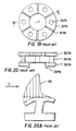
- FIG. 19-20 An alternative to the complex Kingsbury shoe-type bearing is the unitary pedestal bearings shown in Figures 19-20 of the accompanying drawings.
- This bearing has been employed in, among other things, deep well pumps. This relatively simple structure is typically formed by sand casting or some other crude manufacturing technique because heretofore, the specific dimensions have not been deemed important.
- the bearing is structurally characterized by a flat base 36PA having a thick inner circumferential projection 38PA, a plurality of rigid pedestals 34PA extending transversely from the base and a thrust pad 32PA centered on each rigid pedestal.
- Figure 20(A) illustrates schematically, the deflection of the bearing of Figures 19-20 in response to movement of the opposing thrust runner in the direction of arrow L.
- the deflected position (greatly exaggerated) is illustrated in solid lines and the non-deflected position is illustrated in phantom.
- the curve PD in Figure 20(A) illustrates the pressure distribution across the face of the pad. Under load, the thrust pads deflect around the rigid pedestals in an umbrella-like fashion as shown in Figure 20(A). By virtue of this umbrella-like deflection, only a partial hydrodynamic wedge is formed. Consequently, there is an uneven distribution of pressure across the face of the pad as illustrated in Figure 20(A).
- the bearing has proportionately less hydrodynamic advantage compared to a bearing in which a hydrodynamic wedge is formed across the entire thrust pad face.
- the rigidity of the pedestals and flat inflexible base prevent the deflections necessary to optimize wedge formation.
- each bearing pad is supported on a short pillar or stub-like primary portion that is in turn supported by an annular plate-like secondary portion having on its side opposite to the bearing pads a set of feet constituting a tertiary support portion and disposed in quincunx relationship to the stub-like primary portions.
- the plate-like secondary portion is undulated and the primary portions are disposed in the lowest parts (troughs) on their side of the secondary portion while the feet are correspondingly disposed in the troughs on the opposite side, and thus, at the crests of the undulations on the side carrying the bearing pads.
- the secondary portion thus has some flexibility in the direction of the thrust loads carried by the bearing pads and can allow these to deflect in that direction to equalise their loadings.
- the bearing pads and their support structure comprising the primary, secondary and tertiary portions are unitary.
- Prior art hydrodynamic bearings often suffer from fluid leakage which causes breakdown of the fluid film.
- the leakage primarily occurs at the axial ends of the bearing pad surface.
- the leakage primarily occurs at the outer circumferential periphery of the pad surface as a result of centrifugal forces acting on the fluid.
- wedge formation is optimized, fluid leakage is minimized.
- the present invention discloses a pad type thrust or combined radial-thrust bearing, an arrangement including the same and methods making the same as defined in the appended claims.
- the pad type bearing is preferably formed from a single piece of heavy walled tubing or a cylindrical journal that has been machined or formed with small grooves and slits, bores or cuts through or on the bearing wall to define a plurality of thrust pads unitary with a support structure capable of supporting the pads for movement in the six degrees of freedom (i.e., translation or movement in the +x, -x, +y, -y, +z and -z directions and rotation about the X, Y, and Z axes) so as to optimize formation of the hydrodynamic wedge.
- degrees of freedom i.e., translation or movement in the +x, -x, +y, -y, +z and -z directions and rotation about the X, Y, and Z axes
- the bearings of the present invention are designed in three dimensions to provide deflection with six degrees of freedom so as to ensure optimum wedge formation at all times.
- a hydrodynamic bearing operates most effectively when the hydrodynamic wedge has several characteristics.
- the wedge should extend across the entire pad surface; the wedge should have an appropriate thickness at all times; the wedge should be shaped so as to minimize fluid leakage; the wedge should accommodate misalignment such that the major axis of the bearing is colinear or substantially parallel to the axis of the shaft; and the wedge should be formed at the lowest speed possible to prevent damage to the wedge forming surface which generally occurs as a result of shaft tc pad surface contact at low speeds.
- the loading among the spaced bearing pads should be equal.
- the bearings are preferably designed to provide the minimum film thickness necessary to support the shaft at maximum load.
- the support structure is unitary and comprises support stubs, beams, and/or membranes connected to a housing which is sometimes defined by a housing into which the bearing is mounted.
- the inventor has discovered that in many specific applications such as in high speed applications, it is necessary to examine and evaluate the dynamic flexibility of the entire system consisting of the shaft or rotor, the hydrodynamic lubricating film and the bearing.
- computer analysis of this system using a finite element model it has been determined that it is necessary to treat the entire bearing as a completely flexible member that changes shape under operating loads.
- bearing characteristics may be achieved that provide stable low friction operation over wide operating ranges.
- a number of variables have been found to substantially affect the bearing's performance characteristics. Among the most important variables are the shape, size, location and material characteristics (e.g.
- the shape of the support members has been found to be particularly important. Also by providing a fluid backing to the flexible members, a high degree of damping may be achieved that further adds to system stability. In some instances, this damping has replaced secondary squeeze film dampening that is present when the oil film is present between the casing of the bearing and the housing.
- the inventor has also discovered that with respect to gas or air lubricated deflection pad bearings, there are instances where loads or speeds exceed the capability of a gas film. In these cases, it is necessary to introduce a liquid type lubricant into the converging wedge without providing a liquid reservoir or bath.
- the present invention provides a bearing which solves this problem by providing liquid lubricant when necessary.
- bearings of the present invention include electric motors, fans, turbochargers, internal combustion engines, outboard motors, and compressors/ expanders. Test speeds have exceeded 300,000 r.p.m. It is noted that the cuts, grooves and openings in addition to allowing the bearing pad to move to form a converging wedge for hydrodynamic lubrication, allow the pad itself to deflect and change shape by for example flattening. This improves operating performance by, among either things, changing the eccentricity of the bearing.
- the bearings may be formed of metals, powdered metals, plastics, ceramics or composites. When manufactured in small quantities, the bearings are typically machined by facing, turning, and milling the blanks to form larger grooves or openings; smaller grooves are formed by water-jet cutting, electrical discharge or laser machining methods and allow total design flexibility to tune the bearing to provide desired characteristics. Tuning will essentially change the stiffness that in turn eliminates vibration. Manufacture of larger quantities of a single type bearing is preferably accomplished through injection molding, extrusion, powdered metal die casting, investment casting or some similar manufacturing technique. In accordance with one aspect of the present invention, intermediate quantities of bearings are manufactured according to a novel method combining machining and investment casting techniques. The present invention also contemplates easily moldable bearings which include no hidden openings such that they can be molded in a simple two-piece mold. In general, the bearings of the present invention can be manufactured at a fraction of the cost of competitive bearings.
- the present invention provides an orientation that allows for comparable deflections within a smaller envelope allows for movement of the bearing pad in any direction (i.e., six degrees of freedom) to form a converging wedge shape; allows for the pad itself to change shape (e.g., flatten) to improve performance; allows for development of a membrane damping system for improved stability; and allows the bearings to compensate for misalignment of the supported part or shaft and to equalize loading among the bearing pads. All of these characteristics contribute to formation of an optimum hydrodynamic wedge.
- the degree of deflection in the bending mode is, in part, a function of the stiffness of the support structure.
- the pad itself may be made to deflect under a load to form a different shape by providing internal cuts beneath the pad or by undercutting the edges of the pad. In either case the cuts are specifically made to result in a predetermined shape under load.
- a damping element may be added to the design.
- the need for close tolerances between the bearing pad and the shaft portion to be supported can be obviated by dimensioning the bearing so as to eliminate the spacing between the bearing pad and the shaft portion to be supported while at the same time dimensioning the support structure such that the axial stiffness of the bearing is less than the corresponding fluid-film stiffness of the supporting fluid.
- the entire pad or only a portion thereof can be pre-biased into contact with the shaft. For instance, with extremely flexible bearings it may be desirable to pre-torque the entire bearing pad into contact with the shaft. On the other hand, in some instances it is advantageous to pre-torque only the trailing edge of the bearing pad into contact with the shaft so as define a hydrodynamic wedge.
- the bearings of the present invention can be designed to have an interference fit when installed on the shaft.
- the pad support structure deflects slightly to form a converging wedge shape while in the installed, static position with contact between the bearing pad and the shaft at the trailing edge.
- an appropriate spacing between the pad and the shaft will be established instantaneously upon rotation of the shaft by virtue of the stiffness of the fluid-film. This is because the fluid film enters the wedge and builds up fluid pressure causing separation of the shaft and pad.
- the relatively stiff fluid causes the relatively flexible beam support structure to deflect until the stiffness of the support structure is equal to the fluid film stiffness. The instantaneous formation of the fluid film protects the surface of the bearing pad from damage which occurs at low start-up speeds when there is direct contact between the pad and shaft.
- Interference fit bearings of the aforementioned type allow a much larger variation in machining tolerances.
- a relatively large (e.g. 0,07 mm (.003 inch)) variation in the interference fit can be designed to have an insignificant impact on the wedge. This is particularly critical for gas lubricated bearings where prior art bearing forms require extraordinarily precise machining for proper operation.
- the present invention relaxes machining requirements.
- the thrust bearings of the present invention can be designed to provide a statically loaded wedge.
- the thrust bearings of the present invention can be designed such that the bearing pads are biased so that the inner circumferential edge of the bearing pad extends away from the shaft and so that the trailing edge extends toward the shaft.
- the bearing pad slopes toward the shaft in the radial direction (when moving outwardly from the axis). Further, the bearing pad slopes toward the shaft from the leading edge to the trailing edge. In this way a statically loaded wedge approximating the optimum wedge is formed and appropriate spacing between the pads and shafts is established instantaneously upon rotation of the shaft.
- the pad movement may be directed toward the shaft to hold shaft location and to give the pad the ability to adjust for misalignment of the shaft and unequal loading among pads.
- the present invention may apply to thrust or combined radial and thrust forms of bearings and may be one or two directional in nature, depending on the configuration of the bearing. More specifically, if the bearing support structure is symmetrical about the bearing's pad circumferential center line, the bearing will be bidirectional, i.e., capable of supporting a shaft for rotation in two directions in an identical fashion. However, if the bearing support structure is non-symetrical about the bearing's pad circumferential center line, the bearing will deflect differently when supporting a shaft for rotation in a first direction as compared to rotation in the opposite direction.
- the characteristic feature of the bearings of the present invention is that the bearing pads are supported for deflection so as to retain the hydrodynamic fluid, thus obviating the problem of fluid leakage.
- the pad is supported so as to tilt toward the bearing's inner diameter under load so as to prevent centrifugal leakage.
- the primary support structure having at least one support that supports the bearing pad at a location closer to the bearing outer diameter than to the bearing inner diameter.
- the primary support structure includes two or more radially spaced beams, the overall support structure must be designed to cause deflection of the bearing pad at the inner end.
- the bearing pad is supported by a plurality of radially spaced beams and the region between the beams is not directly supported, the pad will tend to deflect so as to form a concave fluid retaining channel.
- the bearings of the present invention are also contemplated.
- the selection of a particular method of manufacturing depends largely on the volume of the particular bearing to be manufactured and the materials used.
- the bearings are preferably manufactured from metallic cylindrical blanks such as heavy wall tubing or other journals which are machined to provide radial and/or facing bores or grooves and formed with radial cuts or slits through either numerically controlled electrical discharge manufacturing techniques, numerically controlled laser cutting techniques, or numerically controlled water-jet cutting.
- the bearings of the present invention are preferably manufactured using an investment casting method in accordance with the present invention.
- the bearings of the present invention can be manufactured using a wide variety of materials such as plastics, ceramics, powdered and non-powdered metals, and composites. In high volume applications, a number of manufacturing methods including injection molding, casting, powdered metal, die casting, and extrusion can be economically employed.
- the bearings of the present invention can be formed in a shape which is easily moldable.
- the present invention relates to thrust and compound radial and thrust hydrodynamic bearings as defined in claim 1 and arrangements including the same as defined in claim 27 which perform significantly better than known bearings and arrangements and can be manufactured at a fraction of the cost of competitive bearings.
- the invention also relates to an advantageous method of making a bearing as defined in claim 28 comprising forming a cylindrical blank having a central axis; forming a central bore in the cylindrical blank, the central bore having a central axis which is coincident with the axis of the cylindrical blank; machining the cylindrical blank so as to define a plurality of circumferentially spaced bearing pads and unitary support structure that supports the bearing pads for movement with six degrees of freedom so as to optimize wedge formation.
- the machined cylindrical blank may be used as a model for forming the bearing by various techniques, including casting, injection molding, powdered metal shaping and sintering.
- the method further comprises the step of forming a radial groove around the circumference of the cylindrical blank.
- the inventive method also comprises the advantageous step of forming a facing groove on one of the opposed circular faces of the cylindrical blank.
- the inventive method additionally comprises the steps of encasing the machined cylindrical blank in molten rubber, allowing the rubber to harden, splitting the rubber, removing the machined cylindrical blank to yield an open rubber mold, pouring molten wax into the rubber mold, allowing the wax to harden into a wax casting, removing the wax casting from the rubber mold, encasing the wax casting in molten plaster, allowing the plaster to harden so as to form a plaster mold, providing at least one opening in the plaster mold, pouring molten bearing material into the plaster mold so as to melt the wax casting and replace the molten wax with molten bearing material, allowing the molten bearing material to harden and removing the plaster from the hardened bearing material.
- a further advantageous step comprises filing the spaces between the bearing pads and the openings within the unitary support structure with a porous plastic material.
- Figures 19 - 20 illustrate prior art as an aid to understanding the problems addressed by the invention.
- Figures 1 to 14 illustrate journal (radial) bearings, and their manufacture, that do not form part of the present invention, being the subject of EP-A-0 317 621 (Application No. 88 906 301.2) that while unpublished at the priority date hereof, claims an earlier priority date.
- Figures are presented herein to illustrate principles of construction and manufacture applicable to the construction and manufacture of the thrust bearings of the present invention.
- other Figures illustrate radial bearings that do not form part of the present invention but incorporate features applicable to the thrust bearings of the invention.
- the bearing structures are formed from a cylindrical blank by providing grooves, slits, bores and other openings in the cylindrical blank. As noted below, this is sometimes a useful technique for manufacturing a prototype bearing.
- the reference to the cylindrical blank is primarily intended to assist understanding of the present invention. It should be noted that although many of the bearings of the present invention could be manufactured from a cylindrical blank, it is not necessary that any of them be so manufactured. Indeed the bearings can be manufactured in numerous ways, some of which are discussed hereinafter.
- the structure therein illustrated is a sector of a journal bearing assembly having grooves and slits formed therein so as to define a housing 10 and a plurality of circumferentially arranged bearing pads 12 each of which is supported by a support structure which includes the housing, a beam 14 and a stub section 16.
- the bearirg defined by the grooves and slits is non-symmetrical about the pad circumferential center line ( Figure 3, 13a).
- the bearing illustrated is a radial unidirectional bearing, i.e., it is adapted for radially supporting a shaft for rotation in only one direction.
- the bearing supports the shaft 5 only for rotation in the counter-clockwise direction illustrated by the arrow.
- the bearing were symmetrical about the center line of the pad, it would be capable of supporting the shaft 5 for either clockwise or counter clockwise rotation, i.e., the bearing would be bidirectional.
- Each bearing pad 12 includes a leading edge 15 and a trailing edge 17.
- the leading edge is defined as the edge first approached by a point on the circumference of the shaft as it continues to rotate.
- the trailing edge is defined as the edge approached circumferentially later by the same point on the shaft as it continues to rotate.
- the shaft 5 is rotating in the proper direction, the point moves, or a fluid film, from the leading edge across the bearing pad and off the trailing edge.
- Optimum performance is obtained when the stub-section 16 supports the bearing pad 12 and hence any load, at a point 16a ( Figure 3) between the circumferential center line 13a of the pad 12 and the trailing edge 17, preferably closer to the center line 13a.
- the beam 14 should also pivot about a point 14a which is located angularly between the leading edge and the trailing edge so that as a result of deflection of the beam 14, the trailing edge 17 deflects inwardly.
- the degree of deflection depends on, among other things, the shape of the beam and the length of the cuts or slits formed in the bearing.
- journal bearings or thrust bearings operate on the principle of formation of a hydrodynamic wedge.
- the major axis of both journal bearings and thrust bearings is the central axis of the cylindrical blank from which the bearing is formed.
- the circumferential pad center line is the radially extending line passing through the geometric center of the pad and the major axis of the bearing. Accordingly, if either a thrust bearing or a journal bearing is symmetrical about this center line axis, i.e. the major axis, the bearing will be bidirectional.
- journal bearings support circumferential portions of shafts
- thrust bearings support shoulder or axial end portions of shafts.
- Other differences follow from this fundamental difference.
- a journal bearing generally has a built-in wedge due to differences in the shaft and bearing diameters; conversely, there is no such built-in wedge in thrust bearings.
- journal bearings particularly hydrodynamic journal bearings
- thrust bearings typically only carries load.
- design of journal bearings is significantly more complicated than the design of thrust bearings. In part, this is because of the constraints imposed by the need to limit the radial envelope of the journal bearings. In order to accommodate these differences the configuration of the thrust bearings is naturally somewhat different than that of journal bearings. Nevertheless, as is evident from this disclosure, many of the principles discussed herein are applicable to either thrust or journal bearings.
- the pad 12 is provided with an arcuate face 13 which corresponds essentially to the radius or arc of the outer diameter of the shaft which the pad will be supporting (via the fluid film) and each pad is defined by axially extending and radially extending edges.
- the axially extending edges comprise the leading and trailing edges.
- the beam is shown both in a static position (solid lines) and in a deflected position (phantom lines) in Figure 3.
- the basic construction of the support structure as illustrated in Figure 1, is created by the use of small slits or cuts through the wall. Typically these slits or radial cuts are from 0,05 to 3,15 mm (0.002 to 0.125”) wide.
- the degree of deflection can be varied by varying, among other things, the length of the cuts. Longer cuts provide a longer moment arm which yields greater deflection. Shorter cuts yield beams having less flexibility and higher load carrying ability. In selecting a length of cut or slit, care must be taken to avoid resonance.
- the deflection downward about the connection point 16a will result in inward movement of the trailing edge 17 of the pad 12, outward movement of the leading edge 15 and a slight flattening of the pad 12 as seen in the dotted lines of Figure 9.
- the gap between the pad face 13 and the outer surface of the shaft 5, through which fluid flows becomes wedge shaped to yield the well-known hydrodynamic support effect.
- the ratio of the spacing between the trailing edge and the shaft versus the spacing between the leading edge and shaft is between 1:2 to 1:5. In other words, the spacing between the leading edge and shaft should be between 2 to 5 times greater than the spacing between the trailing edge and the shaft.
- FIG. 4 there is shown a second illustrative example of a journal bearing formed with slits or cuts and grooves to define a bearing housing 30 with a bearing pad 32 that is supported from the housing by a support structure which includes a beam having a pair of beam portions 34a, 34b which extend substantially in a single line away from the pad. Moreover, the pad may be undercut so that it is supported by the beams only on a pad support surface 34ps. Referring to Figure 5, it will be seen that the beams 34, 34a have a convenient stub beam end as at 36, 36a which acts as a cantilever support for the beam.
- Figure 5 shows only a portion of the pad 32.
- the complete pad is illustrated in Figures 5A and 5B which show possible modifications of the bearings illustrated in Figure 4.
- the pad support surface 34ps is located closer to the trailing edge 37 than the leading edge 35. With this construction, twisting of the beam, as illustrated in Figure 7, will take place intermediate the beam and create the torsional deflection illustrated. Again the primary flexibility is developed by small cuts or slits through the bearing housing wall.
- These cuts provide the bearing pad with six degrees of freedom (i.e., the pad can translate in the +x,-x, +y,-y, +z and -z directions as well rotate about the x, y and z axes) and are designed to optimize hydrodynamic wedge formation. If the cuts or slits were terminated before breaking through to form beam portions 34a and 34b, the pad 32 would be supported by a continuous cylindrical membrane 34m as shown in Figure 5A. The membrane acts as a fluid damper upon which the pad 32 is supported. The termination of the cuts would occur at Point A and Point B of Figure 4. The flexibility of the membrane combined with the fluid lubricant, provides a means to vary the damping action and to isolate the pad from the housing.
- the damping takes the form of a dashpot that exhibits high damping characteristics.
- the bearing illustrated in Figures 4-7 is non-symmetrical about its pad center line and is therefore a unidirectional bearing. Accordingly, the bearing has a leading edge 35 which deflects outward and a trailing edge 37 which deflects inward to forms a wedge.
- the wedge ratio ratio of spacing between the trailing edge and the shaft to the spacing between the leading edge and the shaft
- the location of the center of action of the load which is primarily determined by the location of pad support portion 34ps of the beam 34 with respect to the pad should, again, be between the circumferential center of the pad face and the trailing edge, preferably closer to the circumferential center of the pad face.
- the beam may be defined more simply than shown in Figure 5 by simply extending the cuts or slits downward from points A and B.
- FIG 8 there is shown a third illustrative example of a journal bearing in which internal slits or cuts are provided to create a beam on beam support structure.
- the bearing is formed with grooves and slits or cuts to define a pad 40 which is supported from a housing by beams 42 and 44.
- the pad is connected to the beams at support stubs 40a and 40b.
- Beam attachment to the housing is at support stubs 46 and 48.
- the bearing consists of the thin cuts or slits shown cut through the bearing wall.
- the cut or slit 60 below the pad surface introduces additional flexibility such that under load the pad changes shape to form an airfoil for the introduction of lubricant.
- the pad acts as a spring like membrane.
- Figure 10A shows the deflected shape of the pad 40 under load.
- the pad can be formed and supported so as to deflect to an airfoil shape under load.
- the airfoil dramatically improves performance.
- the pad is capable of displacement in the x, y, and z directions as well as rotation about the x, y, and z axes, that is, the pad has six degrees of freedom. Again, the structure allows optimal hydrodynamic wedge formation.
- Figures 31 and 31A illustrate another example of a journal bearing.
- the bearing construction illustrated in Figures 31 and 31A differs from the previously described journal bearing constructions in that the bearing is bidirectional, i.e., the bearing is capable of supporting a shaft for either clockwise or counterclockwise rotation as viewed in Figure 31.
- the bearing is bidirectional because the pads are symmetrical about their center lines which are defined as the radial extending line passing through the bearing's major axis (606) and the geometric center of the pad.
- the bearing of Figures 31 and 31A is formed with a plurality of thin radial and circumferential slits to define a plurality of circumferentially spaced bearing pads 632.
- each bearing pad 632 is supported by a beam support structure at two pad support surfaces 632ps.
- the beam network connected to the bearing pads at each pad support surface 632ps is identical yielding the symmetrical construction of the bearing which makes the bearing bi-directional. For purposes of simplifying this description, only the network of beams which supports the bearing at one pad support surface will be described since the other pad support surface is supported in an identical fashion.
- a first, generally radially extending, beam 640 is connected to the bearing pad 632 at the pad support surface 632ps.
- a second, generally circumferential, beam 642 is connected to the radially outermost end of beam 640.
- a third, generally radial, beam 644 extends radially inward from the beam 642.
- a fourth, generally circumferential, beam 646 extends from the radially innermost portion of the beam 644.
- a fifth, generally radial beam 648 extends radially outwardly from a beam 644 to the housing portion of the support structure.
- the housing portion of the support structure can be designed to act as a plurality of beams or membranes.
- the cut or slit formed below the pad's surface introduces additional flexibility such that under load the pad changes shape to form an airfoil for the introduction of lubricant.
- the pad acts like a spring-like membrane.
- Figure 31A is a radial cross-section of Figure 31 showing the third beam 644, the bearing pad 632 and the housing.
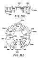
- Figures 32, 32A and 32B illustrate another journal bearing construction which differs from the previously described bearing constructions in that the bearing pads and support structure are defined by relatively large grooves and openings formed in a cylindrical blank. Normally, this type of construction would be formed by milling the blank rather than electrical discharge machining or some other similar technique for forming small grooves as with the previously described embodiments.
- An advantage of the bearing construction illustrated in Figure 32 is that in applications requiring extremely small bearings it is easier to form precisely the proportionately larger cuts and openings required to form a bearing of the type illustrated in Figures 32, 32A and 32B as compared to the proportionately smaller cuts and openings required by the construction of, for example, Figures 1, 4 and 8.
- the large grooves or openings are generally easier to mold or extrude. Bearings formed by larger cuts also find use in applications requiring extremely large bearings with stiff bearing pad support structures.
- the bearing pads shown in Figure 32 are vertical about their pad center line 706A. Hence, the bearing is bidirectional. Moreover, as best shown in the perspective view of Figure 32B the bearing has a continuous cross-section with no hidden openings. Hence, it is easily extrudable and easily moldable. Naturally, the support structure can be altered by providing discontinuities in the cross-section, e.g., by providing radially extending circumferential grooves or non-symmetrically disposed radially extending openings to alter the support structure and thereby alter the performance characteristics.
- the bearing's major axis is 706.
- the bearing includes a plurality of circumferentially spaced bearing pads 732.
- Each bearing pad 732 is supported by a support structure which includes a pair of generally radial beams 740 connected to the bearing pad 732 at a pad support surface.
- a second, generally circumferentially extending, beam 742 supports each of the beams 740.
- Beams 742 are connected to the housing by support stubs 744 in a cantilever type fashion.
- the beams 740 can be regarded as a primary support structure; the beams 742 can be regarded as a secondary support structure; and the beams 744 can be regarded as a tertiary support structure.
- the second beams 742 shown in Figure 32 are defined by forming a plurality of axially extending circumferential grooves 750 in the housing of the support structure. In order to maintain the symmetry of the bidirectional bearing, these grooves are circumferentially spaced about pad center lines 706A in a manner identical to the circumferential spacing of the bearing pads 732. Naturally, similar circumferentially spaced radial grooves could be provided in any of the previous bearing constructions. For instance, as noted above, such grooves could be formed in the periphery of the bearing construction illustrated in Figures 31 and 31A to provide a further beam-like support.
- Figure 32A is a radial cross-section of a portion of the bearing illustrated in Figure 32. In this cross-section, the bearing pad 732 and first beam 740 are visible.
- Figure 32B is a perspective view of the bearing of Figure 32. It should be noted that although the peripheral, circumferential and cylindrical portions of the bearing are depicted in a somewhat segmented fashion to emphasize the curvature, these curved surfaces are in fact continuously curved.
- Figure 33 illustrates another journal bearing construction.
- the bearing of Figure 33 is formed by proportionately large grooves and bores.
- a plurality of equally spaced radially extending circumferential grooves define a plurality of circumferentially spaced bearing pads 832.
- the bearing pads 832 are further defined by a pair of axially extending circumferential grooves which extend symmetrically from the planar faces of the cylindrical blank and are best seen in Figures 33B and 33C in which the grooves are indicated by the reference numerals 834 and 835.
- the bearing support structure is defined by the aforementioned structural features and by a plurality of circumferentially spaced symmetrically disposed shallow bores 838 and a plurality of circumferentially spaced symmetrically disposed deep bores 837. Because of the presence of the "hidden" bores 837, 838, the bearing construction of Figure 33 is not extrudable and not moldable in a simple two-piece mold, i.e., easily moldable.
- the deep bores 837 intersect the axial grooves 836 so as to define support structures for each bearing pad.
- the support structure is further defined by a circumferential groove 839 extending from the outer periphery of the cylindrical blank.
- a support structure for the bearing pad 832 which includes a beam 840 directly supporting the pad, i.e. a primary support structure.
- Figures 34 and 34A-34D illustrate another journal bearing construction.
- the bearing construction of Figure 34 is similar to that of Figure 33 insofar as the bearing pads and their support structures are defined by proportionately large grooves and bores as shown in the drawings.
- the support structure for the bearing pads 932 is like the support structure for the bearing pads 832.
- the support structure for each of the bearing pads 932 is identical, the support structure is not symmetrical with respect to each bearing pad.
- the bearing illustrated in Figure 34 is unidirectional.
- the support structure includes "hidden" openings, the bearing is neither extrudable or moldable in a simple two-piece mold.
- the bearing support structure includes a primary support structure comprising a pair of beam-like menbers 940 which are connected to the bearing pads 932 and defined in part by symmetrically disposed openings 942.
- a shallow circumferential groove formed on the outer periphery of the bearing defines a tertiary support structure comprising a pair of continuous beam-like elements 982.
- a secondary support structure comprising a beam and membrane network 960 for connecting the beams 940 to the continuous beams 982 is defined by the provision of a plurality of large symmetrically disposed bores 944, the provision of smaller symmetrically disposed bores 946, and the provision of small non-symretrically disposed bores 948.
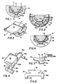
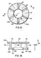
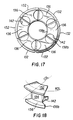
- FIGS 15-18 illustrate a unitary hydrodynamic thrust bearing in accordance with the present invention.
- thrust bearings in accordance with the present invention incorporate some of the same features as the journal bearings that have been described.
- the thrust bearings of the present invention have a major axis defined as the central axis of the blank from which the bearing is formed.
- the bearing pads have a circumferential center line extending radially from the major axis through the geometric center of the pad.
- the thrust bearing is symmetrical about its circumferential center line it is bidirectional; when the bearing is non-symmetrical about its circumferential center line, it is unidirectional.
- the thrust bearings have a slightly different configuration. For example.
- the thrust bearing shown in Figures 15-18 includes a plurality of bearing pads 132 of substantially identical configuration.
- Figure 18 shows the circumferential dividing line CDL and radial dividing line RDL of the bearing pad 132.
- the bearing pad surfaces of the bearing pads 132 lie in a plane which is essentially tranverse to the axis of the shaft to be supported and the bearing's major axis.
- the surface of the bearing pads may become somewhat non-planar or be somewhat skewed with respect to the major axis or the axis of the shaft to be supported.
- a particularly important consideration in the design of thrust bearings of the present invention is the prevention of fluid leakage. To a large extent this objective is achieved by designing the support structures such that under load the inner edge of the bearing pads deflect downward (as viewed in Figure 16) and the outer edge deflects upwardly. All of the thrust bearings described herein are designed in this manner. For instance, in the bearing shown in Figure 16 the beam 134 is connected to the pad 132 at a pad support surface 134ps which is closer to the outer edge of the bearing pad than it is to the inner edge of the bearing pad. Thus, the pad support surface 134ps is located radially outward of the radial dividing line RDL shown in Figure 18.
- the bearing is designed such that, under load, the inner edge of the bearing deflects downward.
- the downward deflection of the inner edge of the bearing pad corresponds to deflection away from the shaft supported and the upward deflection of the outer edge of the bearing pad corresponds to deflection toward the shaft.
- the deflected orientation of the bearing pad significantly inhibits the loss of fluid which otherwise occurs as a result of centrifugal forces acting on the fluid.
- the loss of hydrodynamic fluid can be further reduced by supporting the bearing pad such that under load, the bearing pad deforms to form a lubricant retaining pocket.
- such support is achieved when the bearing pad is supported by a plurality of radially or circumferentially spaced beams and the region between the beams is not directly supported such that the unsupported central region of the pad will tend to deform outwardly so as to form a fluid retaining channel.
- Figure 29 which is discussed below, illustrates an example of a bearing having the requisite radially spaced beams therein. A greater pocket is obtained when beams are spaced further apart.
- a channel can be formed in a journal bearing by providing axially or circumferentially spaced beam supports and an unsupported region between the beams.
- each bearing pad has a chamfer or bevelled edge 132b around its entire periphery.
- the purpose of the chamfer is reduce entrance and exit lubricant losses.
- Each of the bearing pads 132 is supported by primary support portion, which in the illustrated embodiment comprise a beam-like support member 134 supporting the pad at a bearing pad support surface 134ps.
- Each beam 134 is in turn supported by a secondary support portion such as a beam supported beam or membrane 136.
- the beam or membrane 136 is in turn supported by a tertiary support member such as pair of beam-like legs 138a, 138b.
- the continuous membrane 136 becomes a set of beams 136.
- the membrane functions as a continuous membrane.
- the inner beam-like leg 138a could be replaced with short stub-like beams or even eliminated to define a tertiary support such that the secondary support is supported in a cantilever fashion.
- the bearing is symmetrical about the major axis and is therefore bidirectional.
- the holes or openings 142 which divide the continuous membrane into separate beams are round.
- the use of round openings facilitates manufacture of the bearing prototype because circular openings can easily be drilled into the bearing material. This is true of all the bearings described herein. Once such circular openings are provided, it may also be advantageous to extend the openings past the beam or membrane member 136 to the lower portion of the bearing pads 132 so as to define the beam-like members 134. This is why in Figure 15, the cross-section of the pad support surface 134ps and consequently the side walls of the beam 134 have an arcuate appearance.
- the shape of the beam members may be dictated by manufacturing convenience, the shape also affects the performance of the individual bearings.
- the specific shape of the bearings described herein, including the thrust bearing shown in Figures 15-18 is primarily attributable to the ease of manufacturing a prototype, it also has been found to yield excellent results for a specific application. Any changes in the shape would, of course, influence the performance characteristics of the bearing by, for example, altering the bending or twisting characteristics of the beams which support the bearing pad.
- other shapes of beams, pads and membranes are certainly contemplated, both the ease of manufacturing and the effect of the beam pad or membrane's shape on bearing performance must be considered.
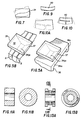
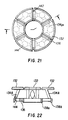
- Figures 21-24 A top view of the bearing as shown in Figure 21; a cross-section of the bearing as shown in Figure 22; a bottom view of the bearing as shown in Figure 23 and a perspective view of the bearing is shown in Figure 24.
- the bearing shown in Figures 21-24 is similar to the bearing of Figures 15-18 with two notable exceptions.
- the bearing of Figures 21-24 includes an angled or slanted support beam 134A rather than a vertical support beam as in Figure 15.
- the bearing includes additional holes 144 which extend through the support beam 136 to form a cylindrical opening through the slanted or angled beam 134 so as to form elliptical openings in the support beam.
- the elliptical openings divide the beam into a pair of complex ligaments, the shape of which can be appreciated with reference to the perspective view of Figure 24.
- the provision of the openings 144 and consequent division of the slanted or angled beams 134A into complex ligaments significantly increases the flexibility of the support structure of the bearing shown in Figures 21-24 as compared to the bearings shown in Figures 15-18.
- the pads 132 of the bearing of Figures 21-24 deflect to form a hydrodynamic wedge in response to a lighter load than do the pads 132 of the bearing shown in Figures 15-18. It follows that the bearing shown in Figures 21-24 is more well suited for supporting light loads and the bearing shown in Figures 15-18 is more well suited for carrying heavier loads.
- angled or slanted support beams such as beam 134A, with or without openings to divide the beam into complex ligaments, increases the flexibility of the pad in the vertical direction since a vertically applied load creates a moment which tends to cause the beam to deflect toward the center or inner diameter of the bearing and thereby eliminate centrifugal leakage of the lubricating fluid.
- Figure 23A shows a bottom view of a bearing of the type shown in Figures 21-24 in which additional holes 146 are formed in the membrane or support beam 136 to enhance the flexibility of the beam or membrane 136 even further.
- the holes 146 are formed nonsymetrically with respect to each bearing segment. The provision of these holes in such a nonsymetrical fashion results in a bearing in which the pads tend to deflect more easily in one direction than in the other direction. In other words, the bearing pads are biased in one direction by the provision of non-symetrical openings in the support structure.
- nonsymetrically disposed openings can be provided in any of the bearing constructions of the present invention in which it is desired to bias the bearing pads in one direction. It may even be desirable to provide the non-symetrically disposed openings or holes such that only selected ones cf the bearing pads are biased.
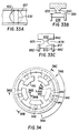
- Figure 25 is a cross-sectional view of another bearing according to the present invention.
- the bearing pad 132 is supported on a pad support stub 134S which is in turn supported on a horizontally oriented beam portion 134H which is in turn supported on an inversely angled beam portion 134I.
- the construction is similar to that of the previously described bearings.
- the bearing has a great deal of flexibility in one direction but it is extremely rigid in the opposite direction.
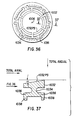
- FIG. 26 A similar construction is illustrated in Figure 26.
- the difference between the bearing illustrated in Figure 26 and the bearing illustrated in Figure 25 is that the bearing illustrated in Figure 26 uses a vertical beam portion 134V rather than an inversely angled beam portion 134I.
- the bearings are similar in all other respects.
- the absence of an angled beam in the bearing of Figure 26 tends to give the bearing more rigidity in the vertical direction.
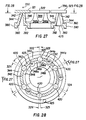
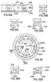
- FIGS 27-28 illustrate another embodiment of the bearing construction of the present invention.
- this bearing includes a plurality of bearing pads 321-326 (shown in phantom in Figure 28). Each of the bearing pads 321-326 is supported on a pad support surface 342 of a bearing support structure.
- the bearing support structure includes a primary support portion composed of a pair of nested frustums supported on a secondary support portion which includes a split peripheral membrane 360 which is supported on a tertiary support portion which includes a pair of peripheral beams 380, 382.
- the peripheral beams 380 and 382 are similar to those of the previously described constructions.
- the membrane 360 differs from the membrane in previously described constructions since the membrane 360 is radially split by the groove formed in the bottom of the bearing support structure which forms the nested frustums.
- the inner frustum is inverted with respect to the outer frustum such that the mean centerlines of the frustums merge at a point 350 above the pad support surface 342 and have a cross-section which appears similar to an inverted V. Since the centerlines of the frustums intersect at point 350 above the pad surface, the primary support structure supports the bearing pad for pivoting about a point above the pad surface. This ensures proper deflection.
- the beams 346 and 344 which support the bearing pad can be angled toward one another at the same angle, angled toward one another at different angles, one beam angled and one beam not angled, and angled in the same direction.
- variations in the degree of angling of the beams in the primary support structure impacts the deflection characteristics of the bearing.
- a plurality of holes or openings 420 disposed symmetrically about the bearing support structure divide the nested frustum or inverted V structure into a plurality of support beams 344, 346 and divide the apex of the nested frustums so as to define the pad support surfaces 342.
- the bearing pad 321 is supported on a pad support surface 342 by a pair of complex support beams 344 and 346 which are tapered toward one another and have a complex geometrical configuration defined by the cylindrically extending openings passing through the nested frustum section.
- the center lines of the beams 344 and 346 intersect at a point 350 above the pad surface to ensure proper pivoting support.
- the individual beams 344 and 346 are supported on a peripheral membrane 360 which is split by the groove which defines the frustums.
- the membrane is supported by peripheral beams 380, 382.
- the peripheral beams 380, 382 and the peripheral membrane 360 can be circumferentially split to define individual beam supports.
- bearing support structure Numerous modifications to the bearing support structure are possible. For example, deflection of the support structure can be modified by changing the angle of the beams, changing the location of the holes or openings which define the legs, varying the length of any of the beams or membranes, and changing the width or thickness of any of the beams or membranes.
- Figures 27 and 28 depict a different support structure for each of the bearing pads 321-326. It should be understood that these various support structures are shown in a single bearing for purposes of illustrating the present invention. In normal use, each of the bearing pads 321-326 would have a similar, though not necessarily identical, support structure to assure uniform performance.
- the support structure for bearing pad 322 differs from that of bearing pad 321 by virtue of the provision of a hole or opening 422 which extends through the beam 346 so as to divide the beam 346 into a plurality of beams or sub-beams 346(a) and 346(b). If, like the opening 422, the diameter and positioning of the opening is such that the beam is completely separated, the beam is divided into separate beams. On the other hand, if the opening only partially separates the beam (e.g. opening 423) the beam is divided into sub-beams. As shown in Figure 27, the opening 422 forms an elliptical opening in the side of the beam 346 such that as viewed in Figure 27, radially outer beam 344 is visible. By virtue of this construction, the pad 322 is supported by three angled ligaments or beams, 344, 346(A) and 346(B).
- Bearing pad 323 is supported by four angled beams or ligaments 344(a), 344(b), 346(a) and 346(b). This structure is achieved by providing a hole or opening 423 which extends through both beam 344 and beam 346 and divides the pad support surface 342 into two sections.
- the size of the openings should be selected based upon the degree to which the beams 344 and 346 are to be divided into separate beams. In some instances it may be desirable to completely separate the beam sections in which case a larger opening would be used. In other instances, such as that illustrated with respect to the support of bearing pad 323, it is desirable to subdivide the beam at some point along the sidewall of the beam. It should also be noted that although the drawings only show the provision of one opening for bearing pad support structure to divide the beams 344 and 346.
- two or more openings similar to that of the openings 422-426 shown in Figure 28 could be provided so as to divide the beams 344, 346 into three or more beams or sub-beams.
- a determination of the type of support to be employed depends on the desired performance characteristics. Generally, dividing the beams into separate beams or sub-beams makes the support structure more flexible. By making the support structure more flexible in one direction as with the support structure for bearing pads 322, 324 and 326 the bearing pads are biased in a predetermined direction.
- the support structure for bearing pad 324 is similar to that for bearing pad 322 except that the opening 424 extends through the outer support beam 344 rather than the inner support beam 346. Thus, like the bearing pad 322, the bearing pad 324 is supported by three angled legs.
- the support structure for bearing pad 325 is similar to that for bearing pad 321 except that an opening 425 is provided through the outer peripheral beam 380 and peripheral membrane 360 in a nonsymetrical position.
- the bearing pad 325 is biased in a predetermined direction, i.e., the direction of greatest flexibility caused by the provision of the opening 425.
- the support structure for the bearing pad 326 is similar to that of bearing pad 322 except that the opening 426 which divides the beam 346 is provided in a nonsymetrical fashion so as to bias a bearing pad 326 in the direction of greater flexibility, i.e., the direction of the smaller, more flexible beam.
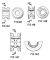
- Figures 29-30 illustrates another embodiment of the bearing of the present invention.
- this bearing includes a plurality of bearing pads 521-526 (location shown in phantom in Figure 30).
- Each of the bearing pads 521-526 are unitary with, and supported on, a bearing pad support structure.
- the bearing pad support structure includes at least a primary support structure including an inner circumferential support beam 546 and an outer circumferential support beam 544, a second support portion including an inner peripheral membrane 362 and a tertiary support portion including an outer peripheral membrane 364 and an inner peripheral support beam 382 and an outer peripheral support beam 380.
- the circumferential support beams 544, 546 are defined in part by a deep circumferential channel extending from the bottom of the bearing to the bearing pad.
- the support beams are further defined by a plurality of holes or openings 620 disposed symmetrically about the bearing pad support structure which separate the beams 544, 546 from adjacent beams.
- the bearing pad 521 is supported on a pair of beams 544 and 546 which beams have generally arcuate side walls.
- the beam support structure also includes membranes 364, 362 and peripheral beams 380, 382.
- Figures 29 and 30 depict a different support structure for each of the bearing pads 521-526. As with the previously described embodiment of Figures 27-28, these various support structures are shown in a single bearing for the purpose of illustrating the present invention. In normal use, each of bearing pads 521-526 would have a similar, though not necessarily identical, support structure to assure uniform performance.
- the support structure for bearing pad 522 differs from that of bearing pad 521 by virtue of the provision of a hole or opening 622 which extends through the inner circumferential beam 546 so as to divide the beam 546 into a plurality of beams 546a and 546b.
- the pad 522 is supported by three vertically extending beams or ligaments 544,546a and 546b.
- the bearing pad 523 is supported by four vertically extending beams or ligaments 544a, 544b 546a and 546b. This structure is achieved by providing a hole or opening 623 which extends through both beam 544 and beam 546. The thinner beams which result from this modification would naturally have greater flexibility than the support structure for bearing pads 522 and 521.
- the bearing pad 524 is supported by five, relatively thin vertically extending beams or ligaments. This structure is achieved by providing a hole or opening 624 to divide the inner beam 546 into two beams and providing two holes 624 to divide the outer beam 544 into three beams.
- the support structure for bearing pad 525 is similar to that for bearing pad 522 except that an additional opening 635 non-symmetrically divides the outer beam 544 into two beams. By virtue of the non-symmetrical division of the outer beam 544, the bearing pad is biased in the direction of greater flexibility.
- the support structure for bearing pad 526 is similar to that for bearing pad 522 except that the outer beam 544 is split rather than the inner beam 546. Further, the opening 626 is somewhat larger than the opening 622 such that a groove is formed on the outer periphery of the inner beam 546 so as to make the inner beam 546 somewhat more flexible.
- Figures 29A, 29B, 30A and 30B illustrate in detail a thrust bearing in which each of the bearing pads 521A has a support structure very similar to that used to support bearing pad 521 in Figures 29 and 30.
- the bearing construction is different, however, insofar as the beams 544A and 546A are circumferentially narrower and vertically shorter than their counterparts in the bearing illustrated in Figures 29 and 30. Naturally, shorter beams are more rigid than the comparatively longer beams and narrow beams are less rigid than comparatively wider beams.
- the beam 544A is radially narrower than the beam 546A; whereas in the bearing illustrated in Figures 29 and 30, the beams 544 and 546 have equal widths.
- the difference in radial thickness is compensated for since the large opening 620 which defines the circumferential extent of the beams 544A and 546A is arranged such that beam 544A is significantly wider in the circumferential direction than is beam 546A.
- the openings 620 are significantly larger than the corresponding openings 620 in the bearing construction of Figures 29 and 30. Naturally, the larger openings increase the flexibility of the support structure defined thereby.
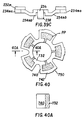
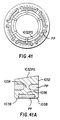
- Figures 35-37 illustrates combined thrust and radial hydrodynamic bearings.
- the bearing illustrated in Figure 35 is quite similar to the bearing illustrated in Figure 34 and similar numerals are used to designate similar structure.
- the bearing of Figures 36-37 is somewhat similar to the radial bearings illustrated in Figures 4 and 14D except that the bearing pad 1032 and the bearing pad support structure, which includes beams and/or membranes 1034, 1036 and 1038, are defined by proportionately larger slits and grooves.
- the radial-thrust bearings differ from radial-only bearings in that the bearing pad surface 1032ps is angled with respect to the major axis 1006. By virtue of its angled pad surface, the bearings of Figures 35-37 support loads acting both along the major axis 1006 and radially from the axis 1006.
- the shaft In order to be supported by the angled pad support face 1032ps, the shaft must be fitted with a runner which is angled at a angle complementary to the angle of the pad support face.
- the support structure for the bearing shown in Figure 35 is similar to the support structure for the bearing shown in Figure 34.
- the support structure for the bearing illustrated in Figures 36 and 37 includes a primary support structure for the spaced bearing pads 1032 having a beam 1034 which supports the bearing pad 1032, a tertiary support structure which comprises a pair of circumferential beams 1038 which may be continuous.
- the secondary support structure comprises a membrane 1036 or a network of beams 1036 for connecting beam 1034 to the beams 1038.
- the support structure for each of the plurality of bearing pads 1032 is nonsymmetrical. Accordingly, the bearing illustrated in Figures 36 and 37 is unidirectional.
- journal bearing constructions described in this application can be employed in the design of combined radial-thrust bearings of the type illustrated in Figures 36 and 37.
- the bearing pad surface must be angled at an angle between 0 and 90 degrees with respect to the major axis.
- the need to accommodate both radial and axial loads necessarily will impact the design of the bearing pad support structure.
- bearing shapes which can be produced by machining a piece of heavy walled tubing or similar cylindrical journal using standardly available machining techniques.
- Such bearings are characterized by the fact that they are formed from a piece of heavy walled tubing or cylindrical or similar cylindrical journal through the provision of bores, slits and grooves.
- the advantage of such bearings is that it is easy to manufacture prototypes and to modify these prototypes after testing.
- the bearings are to be mass produced, using, for example, molding or casting techniques, different manufacturing considerations may dictate different shapes. It is important to recognize that changes in shape affect bearing performance.
- bearing constructions of the present invention are capable of being molded by some molding technique. However, only certain shapes can be injection molded in a simple two-piece mold, i.e., a mold which does not include cams.
- Another advantage of the bearings of the present invention is that the bearings can be constructed with easily moldable shapes which are defined as shapes which can be injection molded using a simple two-piece mold.
- An easily moldable shape generally is characterized by the absence of "hidden" cavities which require cams for molding.
- an easily moldable shape includes no radially extending grooves in the inner and outer diameter and a continuous axial cross section.
- the bearing shown in Figures 32, 32A and 32B is an example of an example of an easily moldable radial or journal bearing.
- easily moldable thrust bearings are characterized by the fact that they can be molded with a single seam line such that, for example, when viewed only from the top and bottom, all surfaces are visible.
- Figures 38A-38C illustrates an easily moldable thrust bearing.
- the bearing includes a plurality of circumferentially spaced bearing pads 132m and a support structure supporting each of the bearing pads 132m.
- the support structure includes a primary support portion which includes circumferential beams 134mb and 134ma, a secondary support portion which includes radially extending beam 136m and a tertiary support portion which includes the stub-like pair of beams 138m.
- the dimensional of the support structure are somewhat distorted to provide clarity.
- the circumferential beams 134ma and 134mb are shown as extremely thick. Such a beam structure would provide a very rigid support for the bearing pads 132m and in practice, such a rigid support would probably not be necessary or desirable.
- the spaced circumferential beam segments 134ma or 134mb could be formed as a continuous circumferential beam element.
- the secondary support portion could include a plurality of radially extending beams between each bearing pad 132m.
- the primary support structure could be modified to include three or more circumferential beam segments connecting each pair of adjacent bearing pads and/or circumferential beam segments of different radial widths could be used.
- the stub-like beam portions 38m could be provided along the radially extending edges of the beams 136 rather than the circumferentially extending ends.
- the structure could also be varied by varying the length or thickness of any of the elements in the support structure to modify the deflection characteristics of the support structure.
- Figure 38D depicts a different support structure for each of the bearing pads 321m-326m. ln particular, Figure 38D is a bottom view with the modifications illustrated herein. It should be understood that these various support structures are shown in a single bearing for purposes of illustrating the present invention. In normal use, each of the bearing pads 321m-326m would have a similar, though not necessarily identical, support structure to assure uniform performance.
- the support for bearing pad 321m differs from that for the bearing pads 132m in that a oval shaped projection extends from the back of the bearing pad surface to provide a rigid support for the outer circumferential edge of the bearing pad 321m.
- the bearing pad 321m would be extremely rigid at its outer circumferential end.
- the support for bearing pad 322m is similar to that to 321m except that rather than a single large projection, two smaller projections 122m extend from the bottom of the bearing proximate the outer circumferential edge of the bearing pad. Like the projection 120m, these two projections 122m provide rigidity to the outer circumferential edge of the bearing pad 322m. However, this construction allows the bearing to deflect in the unsupported region between the projections.
- the bearing pad 323m is supported by modified support structure which includes a continuous circumferential beam 134ma in the primary support portion.
- the bearing pad 324m includes a continuous inner circumferential beam 134mb. The provision of such continuous beams increases the rigidity of the bearing support structure.
- the support structure for bearing pad 325 is modified by the provision of large openings 142m in the inner beam 134mb and smaller openings 144 in the outer beam 134ma.
- the provisions of these openings increases the flexibility of the beams.
- the larger openings 142 increase the flexibility of the beams to a greater extent than the small openings 144.
- Variants of this support structure include the use of different sized openings or a different number of openings to bias the bearing pad 325m in a predetermined direction.
- the bearing pad 326m is supported by a modified structure in which the primary support portion includes a membrane 134m rather than a pair of beams.
- the primary support portion includes a membrane 134m rather than a pair of beams.
- one of the membranes is provided with a opening 146 to bias the bearing pad 326m in a predetermined direction.
- the provision of the opening 146m is not necessary and if desired, a number of openings could be provided.
- the moldable bearings do not include any hidden cavities which would necessitate the use of a complex mold and/or a mold including a displaceable cam.
- the bearing can be simply molded using a two piece mold. Specifically, a first mold piece defines those surfaces which are directly visible only in the top view of Figure 38A. The second mold piece defines those surfaces which are only visible in the bottom view of Figure 38B. Surfaces having edges visible in both Figures 38A and 38B can be molded using either or both molds.
- easy moldability is achieved because the secondary and tertiary support portions are circumferentially located in the space between bearing pads.
- the modifications illustrated in Figure 38D do not alter the easy moldability of the bearing.
- FIGS 38A-38D More complex variants of the moldable thrust bearing illustrated in Figures 38A-38D are possible.
- any of the previously discussed modifications of the bearing structure which can be adapted to easy molding could be employed.
- the primary support beams could be continuous.
- the provision of an easily moldable bearing does not necessarily require a simple bearing construction.
- An example of a more complex bearing structure is illustrated in Figures 39A-39C.
- the bearing includes a plurality of circumferentially spaced bearing pads 232m supported by a bearing pad support structure.
- the secondary and tertiary portions of the support structure are similar to corresponding portions of the bearing support structure of Figure 38.
- the bearing of Figure 39 differs from the bearing of 38 in that in the bearing of Figure 39 the primary support portion includes a plurality of complex beams 234.
- each bearing pad is supported by a radially outer continuous complex circumferential beam 234ma.
- the pads are further supported by the plurality of spaced circumferential complex beams 234mb.
- FIGS. 40, 40A, 41 and 41A illustrate bearing constructions for achieving this purpose.
- FIG. 40 illustrate a novel self lubricating deflection pad bearing structure in accordance with another important aspect of the present invention.
- the bearing is essentially a deflection pad bearing of the type described herein which has been modified to include lubricating plastic in its various openings.
- the plastic employed in the bearing is a conventional castable porous plastic which is capable of absorbing lubricating liquid when soaked in such a liquid.
- a conventional castable porous plastic which is capable of absorbing lubricating liquid when soaked in such a liquid.
- One such plastic is sold under the tradename POREX.
- the porous plastic can be formed from various plastics by injecting air into the plastic material to form the pores.
- the liquid is absorbed into the porous plastic in a wick like manner and held in place by the plastic.
- the lubricating deflection pad bearing is constructed by taking a conventional journal, thrust or combined radial and thrust deflection pad bearing of the type described above and casting or injecting the conventional porous plastic around and into the spaces between the deflection members.
- the movement of the shaft and the compression of the deflection members causes the lubricating liquid to leave the porous plastic be drawn into the leading edge of the converging wedge.
- the formation of the liquid filled wedge greatly increases the load and speed capability of the bearing. After the liquid passes over the pad surface, it is reabsorbed by the porous plastic after leaving the trailing edge.
- An important aspect of the present invention is the composite structure combining a standard bearing material with the porous plastic.
- this composite it is possible to take advantage of the unique characteristics of both materials. More specifically, conventional porous plastics alone make poor deflection pad bearing materials because the pores in the plastic are actual voids that are detrimental to the development of the very thin fluid film. On the other hand, conventional plastic or metal bearing materials not having the pores are incapable of absorbing lubricant to any great extent.
- an effective self-lubricating hydrodynamic bearing can be obtained.
- there are synergistic results from the combined use of standard bearing material and lubricant absorbing porous plastic for example, the deflections of the bearing surface assist in forcing the liquid lubricant into the leading edge. Moreover, channelling or lubricant retaining deformation of the bearing surface assists in containing the liquid.
- Figures 40 and 41 show two examples of the self lubricating deflection pad bearing.
- these drawings show bearings similar to bearings described previously which have been modified to include the liquid absorbing porous plastic filled into the spaces between the deflection members.
- the bearing acts as a skeletal portion and the porous plastic portion acts as a lubricant retaining and releasing sponge.
- Figures 40 and 40A show a self-lubricating radial bearing having an underlying bearing structure which is essentially identical to the bearing shown in Figures 32 and 32A.
- the bearing structure of Figure 40 is modified such that porous plastic fills the openings between the bearings and the openings within the support structure which are continuous with the spaces between the bearing pads 732.
- the spaces under the bearing pads could be filled with porous plastic as well.
- the provision of such porous plastic areas would be fruitless.
- Figures 41 and 41A show a combined thrust and radial bearing having a construction virtually identical to the construction of the combined radial and thrust bearing shown in Figures 36 and 37.
- porous plastic is again injected into the interstices or spaces within the support structure between the end between the pads.
- the injection of the porous plastic as illustrated results in a bearing having a continuous inner diameter.
- the material characteristics across the inner diameter vary significantly.
- the inner diameter of the bearing of Figure 41 includes wedge supporting bearing pad surfaces and circumferentially spaced lubricant releasing and absorbing and retaining portions.
- the movement of the shaft and the compression of the deflection members causes the lubricating liquid to leave the porous plastic and to be drawn into the leading edge of the converging wedge.
- the formation of the liquid filled wedge greatly increases the load and speed capability of the bearings.
- the manufacture of the self-lubricating deflection pad bearing involves three general steps. First, the basic bearing or skeletal portion is formed standard bearing material. Second, the porous plastic is injected into the desired spaces in the bearing structure. For purposes of manufacturing convenience, the plastic is injected to the bearing without lubricant. Finally, the bearing with the porous plastic injected into the desired spaces is loaded with liquid lubricant. To properly load the plastic with liquid lubricant, it is necessary to wick the lubricant in from one side. The merging in the liquid results in an unfilled internal portion. This is caused by not allowing the pores to vent from one side. In Figure 40 the basic bearing structure is combined radial and thrust structure similar to that shown in Figure 36. However, porous plastic fills the interstices within the support structure.
- the porous plastic yields a composite bearing having a continuous inner diameter surface.
- the deflection characteristics across the surface vary greatly.
- the deflection pads which are formed of standard bearing materials such as metal or non-porous plastic is suited for deflection and formation of a fluid wedge.
- the porous plastic portions are suited for compression so as to release lubricant at the leading edge of the bearing pads and absorbing lubricant at the trailing edge of the bearing pads.
- the bearings of the present invention can be formed to provide for a wedge ratio of 1:2 to 1:5, have a deformable bearing surface the shape of which can be modified, allow six degrees of freedom of the pad, and provide a dashpot type damping action.
- the bearings are typically of a unitary construction.
- the bearing of the present invention exhibits exceptional performance characteristics.
- the bearing dimensions and deflection variables including number, size, shape, location and material characteristics of the elements defined in the unitary bearing can be tailored for any specific application to support a wide variety of loads.
- the bearings of the present invention have a self correcting characteristic resulting from the tendency of the bearing to return to its non-deflected state due to the stiffness of the bearing.
- the stiffness of the bearing is primarily a function of the shape of the support structure, and to a lesser extent the other deflection variables including number, size, location, and material characteristics of the elements defined by the grooves and cuts or slits formed in the unitary element. Stiffer bearings have a greater self-correcting tendency but are less able to adjust for shaft misalignment.
- bearings incorporating the features of the present invention exhibit dramatically improved performance even in comparison to the structure disclosed in the present inventor's prior patent, US-A-4 496 251.
- journal bearings disclosed herein were utilized in a radial bearing with a radial envelope of 2.31mm (0.091"). Inward deflections of the bearing pad were .0076mm (0.0003") which provides exceptional stability and bearing performance.
- a comparable displacement using the arrangement shown in the present inventor's prior patent US-A-4 496 251 would have required a radial space of 7.6mm (0.30").
- the bearings of the present invention can be designed to obviate the need for such close manufacturing tolerances. Specifically, by providing appropriate bores, grooves and cuts or slits, it is possible to define a bearing having virtually any desired performance characteristic.
- One such characteristic is the stiffness or spring characteristic of the bearing pad in the direction of load, i.e., in the radial direction (radial stiffness) with respect to journal bearings and in the axial direction (axial stiffness) with respect to thrust bearings.
- the fluid film between the shaft and the bearing may be modeled as a spring since it has a calculatable radial or axial fluid film stiffness or spring characteristic.
- the fluid film stiffness and the bearing stiffness act in opposition to one another such that if the fluid film stiffness or spring characteristic exceeds the bearing stiffness or spring characteristic, the bearing will deflect in the direction of the fluid film stiffness (i.e., radial direction for journal bearings and axial direction for thrust bearings) until the stiffness of the fluid and the bearing are in equilibrium.
- the radial stiffness of the bearing is, of course, primarily a function of the section or flexure modulus of the support structure which depends on the shape of the support structure.
- the radially stiffness of the pad also depends on the length of the slits or cuts formed in the bearing.
- thrust bearings except, naturally, the axial stiffness of the bearing is critical. Accordingly, with the present invention, it is possible to achieve high performance without the close manufacturing tolerances typically required of hydrodynamic bearings.
- the bearings of the present invention may be designed to have an interference fit when installed on the shaft such that as the bearing is forced on the shaft the pads deflect, slightly so as to form a converging wedge shape while in the stationary installed position, contact between the bearing pad and shaft being at the trailing edge. At the instant of start up, the fluid film enters the wedge and builds up fluid pressure causing separation of the shaft and pad.
- the bearings of the present invention may be designed and dimensioned such that the trailing edge of the bearing is in contact with the shaft portion to be supported when the shaft is at rest.
- the thrust bearings of the present invention can be designed to provide a statically loaded wedge.
- the support structure for the bearings is designed such that the bearing pads slope toward the shaft from the radially inner circumferential edge of the bearing pad to the radially outer circumferential edge of the bearing pad. Further, the support structure is designed such that the bearing pad slopes toward the shaft from the radially extending leading edge to the trailing edge. In this way, a statically loaded wedge approximating the optimum wedge is formed. Further, the pad is sloped toward the shaft at the outer circumferential edge so as to provide the desired fluid retaining characteristic.
- the stiffness of the support structure can also be designed such that an appropriate space in between the pads and shaft is established instantaneously upon rotation of the shaft.
- the bearing may be designed such that the entire bearing pad contacts the shaft portion to be supported when the shaft is at rest.
- This aspect of the present invention is particularly useful in high volume production of the bearings and with bearings using gas lubricating fluids because it allows a much larger variation of machining tolerances.
- a 0,07mm (.003 inch) variation can be designed to have an insignificant impact on the wedge whereas conventionally machining of known gas bearings require 0.00000x tolerance which can only be attained through the use of sophisticated and expensive machining techniques such as micro inch machining via etching.
- the bearings disclosed herein are preferably constructed by electrical discharge machining or laser cutting methods.
- the double lines shown in the drawings are the actual paths of the wire or beam which is typically 0.50-1.52mm (0.002-0.060") in diameter.
- the lubricant that flows into the electrical discharge machined paths acts as a fluid dampener that reduces any vibration or instability at resonant frequencies.
- the damping takes the form of a dashpot that exhibits high damping characteristics.
- a significant consideration in the design is that the support structure length and direction be oriented to provide the inward deflection shown in Figure 3. Also minute deflections of the pads themselves in the direction of load as shown in Figure 9, result in eccentricity changes which further improve bearing performance.
- the bearings are preferably constructed by electrical discharge machining or laser cutting methods. Such small volumes or prototypes are usually constructed of metal.
- other methods of manufacture such as injection molding, casting, powdered metal die casting and extrusion are more economical.
- plastics, ceramics, powdered metals or composites it may be more economical to employ plastics, ceramics, powdered metals or composites to form the bearings of the present invention. It is believed that methods such as injection molding, casting, powdered metal die casting with sintering and extrusion are sufficiently well known that the processes need not be detailed herein.
- the first step of the investment casting procedure is manufacture of a prototype bearing.
- the prototype can be manufactured in any number of ways, but is preferably manufactured by machining a piece of heavy walled tubing or similar cylindrical journal.
- the cylindrical journal typically is machined using a lathe for forming face and circumferential grooves, and a mill for forming axial and radial bores.
- techniques such as water-jet cutting, laser and wire electrical discharge techniques are generally more suitable.
- the journals are typically turned and milled to form the larger grooves.
- this step involves encasing the prototype in molten rubber and allowing the rubber to harden so as to form a rubber mold of the prototype. The rubber encasing the prototype is then split and the prototype is removed to yield an open rubber mold.
- the rubber mold is obtained, it is used to form a wax casting. This step typically involves pouring molten wax into the rubber mold and allowing the wax to harden to form a wax casting of the bearing.
- the wax casting After the wax casting is obtained, it is used to form a plaster mold. This step typically involves encasing the wax casting in plaster and allowing the plaster to harden around the wax casting so as to form a plaster mold.
- the plaster mold can then be used to form a bearing. Specifically, molten bearing material, such as bronze, is poured into the plaster mold so as to melt and displace the wax casting from the mold. Thus, the plaster mold is filled with molten bearing material and the melted wax is removed from the plaster mold.
- molten bearing material such as bronze
- the plaster mold is removed from around the bearing and a bearing is obtained.
- the first step in the investment casting method indeed in any method, of producing bearings in accordance with the present invention is the production of a prototype bearing.
- the relatively complex thrust bearings of the present invention can be formed using simple manufacturing techniques. Similar techniques are used for both thrust and combined thrust and radial bearings.
- Each bearing is initially in the form of a cylindrical blank having a cylindrical bore as shown in Figures 11A and 11B.
- the blank is then machined to provide a radial lubricating fluid groove as shown in Figures 12A and 12B.
- the support beams as viewed in Figure 14A are tapered along lines which converge at a point proximate the center line of the shaft. This ensures that flexibility occurs about the shaft center line by establishing a center of action for the entire system such that the pads may adjust to shaft misalignment.
- the tapering of the support beams causes the bearing to act in a manner similar to a spherical bearing by concentrating the support forces on a single point about which the shaft may pivot in all directions to correct any misalignment.
- the arrows in Figure 14A illustrate the lines of action of the deflection.
- Bearings having cross sections of the type shown in Figures 12A and 14A are particularly effective at retaining the hydrodynamic fluid. This is because the bearing pad is supported proximate the axial ends of the bearing pad and the central portion of the bearing pad is not directly supported. By virtue of this construction, the bearing pad is supported so as to deform under load to form a fluid retaining concave pocket, i.e. the central portion of the bearing pad deflects radially outward. This greatly decreases fluid leakage. Naturally, the degree of pocket formation depends of the relative dimensions of the bearing pad and support structure. A larger fluid retaining pocket could be obtained by providing a thinner bearing pad surface and supporting the pad surface at the extreme axial ends of the bearing pad.
- Figures 12A and 12B After the cylindrical blank is properly machined as shown in Figures 12A and 12B, Figures 13A and 13B, or Figures 14A and 14B radial and/or circumferential slits or grooves are formed along the radial face of the machined blank to define the bearing pads, the beam supports and the housing.
- Figures 14C and 14D illustrate such grooves formed in the machined blank of Figures 14A and 14B.
- the cuts or slits are preferably formed through electrical discharge manufacturing or through the use of a laser.
- the machining of the cylindrical blanks to achieve the configurations illustrated in Figures 12A and 12B, Figures 13A and 13B, Figures 14A and 14B or a similar shape can be done through conventional machine tools such as lathe or the like.
- journal bearings the principles apply just as well to thrust bearings.
- the thrust bearing shown in Figures 15-18 can be formed by machining a section of heavy walled tubing to provide radially inner and outer grooves, facing grooves, axial bores, radial cuts and chamfers so as to define bearing pads and support structure.
- the performance characteristics of the bearings of the present invention results from the relative shape, size, location and material characteristics of the bearing pads and the beam supports defined by the bores and cuts or slits formed in the machined blank. These parameters are largely defined by the dimensions and location of the radial circumferential bores, cuts or slits formed in the bearing in conjunction with the shape of the machined blank in which the bores or slits are formed to yield the bearing.
- bearings of the present invention are most easily understood by reference to the machining process, larger quantities are preferably manufactured through the investment casting method of the present invention, and even larger scale production of the bearings contemplated by the present invention could be more economically performed through injection molding, casting, powdered metal, die casting, extrusion or the like.
- radial lubricating fluid grooves as shown in Figures 12A and 12B can be provided along the length of the pipe-like cylindrical blank prior to extrusion.
- facing grooves were desired in the bearing, these can be individually defined after slicing the individual bearings from the extruded and machined blank. For this reason, extrusion might not be a preferred method of producing bearings which require facing grooves to enhance torsional flexibility.
Landscapes
- Engineering & Computer Science (AREA)
- General Engineering & Computer Science (AREA)
- Mechanical Engineering (AREA)
- Physics & Mathematics (AREA)
- Acoustics & Sound (AREA)
- Aviation & Aerospace Engineering (AREA)
- Fluid Mechanics (AREA)
- Sliding-Contact Bearings (AREA)
Claims (39)
- Hydrodynamisches Axial- oder kombiniertes Achs-Axial-Lager zum Tragen einer sich rotierenden Welle auf einem Fluidfilm, wobei das Lager eine Vielzahl Lagerkissen (132), die Lagerkissenoberflächen besitzen, die so angeordnet sind, um in einen Wellenbereich einzugreifen, um die Welle für eine axiale Schubbelastung zu tragen, und eine Tragestruktur zum Tragen der Lagerkissen aufweist, wobei die Lagerkissen und die Tragestruktur unitär sind und die Tragestruktur einen primären Tragebereich (134), einen sekundären Tragebereich (136) und einen tertiären Tragebereich (138) aufweist, wobei die Tragebereiche dazu geeignet sind, sich relativ zueinander abzulenken und um die Lagerkissen für eine Bewegung mit sechs Freiheitsgraden so zu tragen, daß sich unter Last jedes Kissen zu einer Position ablenkt, in der die nachlaufende Kante des Kissens näher zu dem Wellenbereich als die voranführende Kante des Kissens ist, um so einen optimalen, hydrodynamischen Keil zu bilden, gekennzeichnet dadurch, daß der primäre Tragebereich mindestens einen Träger (134) zum Tragen jedes der Kissen an einer Stelle dichter zu der äußeren Kante des Kissens als zu der inneren Kante des Kissens besitzt derart, daß sich die innere Kante des Lagerkissens nach unten unter Last ablenkt.
- Lager nach Anspruch 1, wobei die Tragestruktur mindestens einen umfangsmäßigen Steg (134), einen längsgerichteten Steg (138) und eine Membran (136) zum Tragen der Kissen für eine Bewegung unter sechs Freiheitsgraden umfaßt derart, daß unter einer normalen Last die nachlaufende Kante jedes Kissens radial nach innen zu dem Wellenbereich abgelenkt wird und die voranführende Kante jedes Kissens radial nach außen abgelenkt wird.
- Lager nach Anspruch 1 oder 2, wobei die Tragestruktur symmetrisch zu den Lagerkissen derart ist, daß das Lager den Wellenbereich für eine Drehung in irgendeiner Richtung tragen kann.
- Lager nach Anspruch 1, 2 oder 3, wobei der primäre Tragebereich in eine Mehrzahl stegähnlicher Kissentrageteile (134A) unterteilt ist, wobei jedes der Vielzahl der Tragekissen (132) durch mindestens eines der Vielzahl der stegähnlichen Kissentrageteile in dem primären Tragebereich getragen wird; wobei der sekundäre Tragebereich (136) jedes der Vielzahl stegähnlicher Kissentrageteile trägt und wobei der tertiäre Tragebereich (138) den sekundären Tragebereich trägt.
- Lager nach Anspruch 1, 2 oder 3, wobei der primäre Trageberelch einen Tragesteg (544,546) aufweist, der im wesentlichen breiter in der umfangsmäßigen Richtung als in der radialen Richtung ist und eine Form und eine Stelle derart besitzt, daß sich unter Last die innere Kante des Lagerkissens nach unten ablenkt.
- Lager nach einem der Ansprüche 1 bis 5, wobei die Lagerkissen und die Tragestruktur durch eine Vielzahl Einschnitte, Nuten und Öffnungen, die in einem unitären Teil gebildet sind, festgelegt sind.
- Lager nach einem der Ansprüche 1 bis 6, wobei die Bewegung der Tragestruktur mittels Fluid gedämpft ist.
- Lager nach einem der Ansprüche 1 bis 7, wobei die Tragestruktur so aufgebaut ist, um sich so abzulenken, um eine Wellenfehlausrichtung aufzunehmen.
- Lager nach einem der Ansprüche 1 bis 8, wobei die Tragestruktur so aufgebaut ist, um sich unter Last so abzulenken, um die Belastungen an den einzelnen Lagerkissen zu egalisieren.
- Lager nach einem der Ansprüche 1 bis 9, das poröses Kunsttoffmaterial besitzt, das die Zwischenräume zwischen den Lagerkissen auffüllt.
- Lager nach Anspruch 10, wobei der poröse Kunststoff zum Absorbieren und Freigeben eines flüssigen Schmiermittels geeignet ist und mit flüssigem Schmiermittel derart beladen ist, daß dann, wenn sich die Tragestruktur ablenkt, flüssiges Schmiermittel aus dem porösen Kunststoff auf die Lagerkissenoberfläche freigegeben wird.
- Lager nach einem der Ansprüche 1 bis 11, das eine einfach gießbare bzw. spritzbare Form besitzt.
- Lager nach einem der Ansprüche 1 bis 12, wobei der primäre Tragebereich jedes Lagerkissens (1032) einen Steg (1034) aufweist.
- Lager nach einem der Ansprüche 1 bis 12, wobei der primäre Tragebereich für jedes Lagerkissen (521) zwei Stege (544,546) aufweist.
- Lager nach einem der Ansprüche 1 bis 12, wobei der primäre Tragebereich jedes Lagerkissens (522) drei oder mehr Stege (544, 546a, 546b) aufweist.
- Lager nach einem der Ansprüche 1 bis 15, wobei der sekundäre Tragebereich einen Steg (1036) aufweist.
- Lager nach einem der Ansprüche 1 bis 15, wobei der sekundäre Tragebereich drei oder mehr Stege aufweist.
- Lager nach einem der Ansprüche 1 bis 15, wobei der sekundäre Tragebereich eine kontinuierliche Membran aufweist.
- Lager nach einem der Ansprüche 1 bis 18, wobei dar tertiäre Tragebereich zwei oder mehr Stege aufweist.
- Lager nach Anspruch 19, wobei dar tertiäre Tragebereich ein kontinuierliches, umfangsmäßiges Stegelement aufweist.
- Lager nach einem der Ansprüche 1 bis 20, wobei die Lagerkissen so aufgebaut sind, um sich in eine konvexe Form unter Belastung abzulenken.
- Lager nach einem der Ansprüche 1 bis 21, wobei die Lagerkissen so aufgebaut sind, um sich in eine Tragflügelform unter Belastung abzulenken.
- Lager nach einem der Ansprüche 1 bis 22, wobei das Lager aus einem Eisenmetallmaterial gebildet ist.
- Lager nach einem der Ansprüche 1 bis 22, wobei das Lager aus einem Nichteisenmetallmaterial gebildet ist.
- Lager nach einem der Ansprüche 1 bis 22, wobei das Lager aus einem Kunststoffmaterial gebildet ist.
- Lager nach einem der Ansprüche 1 bis 22, wobei das Lager aus einem keramischen Material gebildet ist.
- Lageranordnung, die einen Wellenbereich aufweist, der in Rotation auf einem Fluidfilm durch ein Lager gemäß einem der vorhergehenden Ansprüche getragen ist, wobei die Tragestruktur des Lagers so aufgebaut ist, daß die nachlaufende Kante jedes Lagerkissens den Wellenbereich berührt, wenn sich die Welle in Ruhe befindet; und wobei die Tragestruktur eine vorbestimmte Steifheit so besitzt, daß, falls die Welle beginnt zu rotieren, der hydrodynamische Druck des Fluids zwischen dem Kissen und dem Wellenbereich zu einem Punkt ansteigt, an dem die Steifheit das Fluidfilms größer als die Steifheit der Tragestruktur ist, wodurch bewirkt wird, daß sich das Lagerkissen so ablenkte um seine nachlaufende Kante von den Wellenbereich weg zu bewegen, um eine Bildung eines Fluidfilms zwischen der nachlaufenden Kante des Kissens und des Wellenbereich zu ermöglichen.
- Verfahren zur Herstellung eines Lagers nach einem der Ansprüche 1 bis 26, gekennzeichnet durch die Schritte der Bildung eines zylindrischen Rohlings, der eine zentrale Achse besitzt; der Bildung einer zentralen Bohrung in des zylindrischen Rohling, wobei die zentrale Bohrung eine zentrale Achse besitzt, die mit der Achse des zylindrischen Rohlings übereinstimmt; und der spanabbebenden Bearbeitung des zylindrischen Rohlings so, um die Mehrzahl umfangsmäßig beabstandeter Lagerkissen und die unitäre Tragestruktur, die die Lagerkissen für eine Bewegung mit sechs Freiheitsgraden trägt, festzulegen.
- Verfahren nach Anspruch 28, wobei der zylindrische Rohling durch spanabhebende Bearbeitung mittels elektrischer Entladung bearbeitet wird.
- Verfahren nach Anspruch 28, wobei der zylindrische Rohling durch Laserschneiden spanabhebend bearbeitet wird.
- Verfahren nach Anspruch 28, wobei der zylindrische Rohling durch Wasserstrahlschneiden spanabhebend bearbeitet wird.
- Verfahren nach einem der Ansprüche 28 bis 31, wobei der spanabhebend bearbeitete Rohling als Modell zur Bildung des Lagers durch Gießen verwendet wird.
- Verfahren nach einem der Ansprüche 28 bis 31, wobei der spanabhebend bearbeitete Rohling als Modell zur Bildung des Lagers durch Spritzgießen verwendet wird.
- Verfahren nach einem der Ansprüche 28 bis 31, wobei der spanabhebend bearbeitete Rohling als Modell zum Bilden des Lagers durch Pulvermetallformung und -sinterung verwendet wird.
- Verfahren nach einem der Ansprüche 28 bis 31, wobei der spanabhebend bearbeitete Rohling als Modell zur Bildung des Lagers durch Extrusion verwendet wird.
- Verfahren nach einem der Ansprüche 28 bis 31, das weiterhin den Schritt der Bildung einer radialen Nut um den Umfang des zylindrischen Rohlings herum aufweist.
- Verfahren nach einem der Ansprüche 28 bis 31 oder nach Anspruch 36, das weiterhin den Schritt der Bildung einer umfangsmäßigen Nut an einer der gegenüberliegenden, kreisförmigen Flächen des zylindrischen Rohlings aufweist.
- Verfahren nach einem der Ansprüche 28 bis 31, 36 oder 37, das weiterhin die Schritte aufweist: Einhüllen des spanabhebend bearbeiteten, zylindrischen Rohlings in geschmolzenem Gummi; Zulassen, daß sich der Gummi aushärtet; Teilen des Gummis; Entfernen des spanabhebend bearbeiteten, zylindrischen Rohlings, um eine offene Gummigießform zu erhalten; Einfüllen geschmolzenen Wachses in die Gummiform; Zulassen, daß sich das Wachs zu einem Wachsformkern aushärtet; Entfernen des Wachsformkerns aus der Gummigießform; Einhüllen des Wachsformkerns in Gips; Zulassen, daß sich der Gips aushärtet, um so eine Gipsgießform zu bilden; Bilden mindestens einer Öffnung in der Gipsgießform; Einfüllen geschmolzenen Lagermaterials in die Gipsgießform, um so den Wachskernform auszuschmelzen und das geschmolzene Wachs durch geschmolzenes Lagermaterial zu ersetzen; Zulassen, daß sich das geschmolzene Lagermaterial aushärtet; und Entfernen des Gipses von dem ausgehärteten Lagermaterial.
- Verfahren nach einem der Ansprüche 28 bis 38, das weiterhin den Schritt des Auffüllens der Zwischenräume zwischen den Lagerkissen und den Öffnungen innerhalb der unitären Tragestruktur mit einem porösen Kunststoffmaterial aufweist.
Priority Applications (1)
| Application Number | Priority Date | Filing Date | Title |
|---|---|---|---|
| EP94119173A EP0646746A3 (de) | 1988-05-27 | 1989-05-24 | Lager mit auf Trägern montierten Lagersegmenten und ihre Fertigungsmethoden. |
Applications Claiming Priority (5)
| Application Number | Priority Date | Filing Date | Title |
|---|---|---|---|
| US5534087A | 1987-05-29 | 1987-05-29 | |
| WOPCT/US88/01841 | 1988-05-27 | ||
| PCT/US1988/001841 WO1988009443A1 (en) | 1987-05-29 | 1988-05-27 | Beam mounted bearing pad and methods of making same |
| US309081 | 1989-02-08 | ||
| US07/309,081 US5137373A (en) | 1987-05-29 | 1989-02-08 | Bearings having beam mounted bearing pads and methods of making same |
Related Child Applications (2)
| Application Number | Title | Priority Date | Filing Date |
|---|---|---|---|
| EP94119173.6 Division-Into | 1989-05-24 | ||
| EP94119173A Division EP0646746A3 (de) | 1988-05-27 | 1989-05-24 | Lager mit auf Trägern montierten Lagersegmenten und ihre Fertigungsmethoden. |
Publications (3)
| Publication Number | Publication Date |
|---|---|
| EP0343620A2 EP0343620A2 (de) | 1989-11-29 |
| EP0343620A3 EP0343620A3 (de) | 1991-01-16 |
| EP0343620B1 true EP0343620B1 (de) | 1995-06-28 |
Family
ID=26734122
Family Applications (1)
| Application Number | Title | Priority Date | Filing Date |
|---|---|---|---|
| EP89109357A Expired - Lifetime EP0343620B1 (de) | 1987-05-29 | 1989-05-24 | Lager mit auf Trägern befestigten Lagerkissen und ihre Herstellungsverfahren |
Country Status (4)
| Country | Link |
|---|---|
| US (2) | US5137373A (de) |
| EP (1) | EP0343620B1 (de) |
| AU (1) | AU609992B2 (de) |
| GR (1) | GR3017155T3 (de) |
Cited By (1)
| Publication number | Priority date | Publication date | Assignee | Title |
|---|---|---|---|---|
| CN110765692A (zh) * | 2019-11-15 | 2020-02-07 | 一汽解放汽车有限公司 | 一种橡胶o型圈静密封寿命预测方法 |
Families Citing this family (79)
| Publication number | Priority date | Publication date | Assignee | Title |
|---|---|---|---|---|
| US5137373A (en) * | 1987-05-29 | 1992-08-11 | Ide Russell D | Bearings having beam mounted bearing pads and methods of making same |
| US5054938A (en) * | 1987-05-29 | 1991-10-08 | Ide Russell D | Hydrodynamic bearings having beam mounted bearing pads and sealed bearing assemblies including the same |
| US5246295A (en) * | 1991-10-30 | 1993-09-21 | Ide Russell D | Non-contacting mechanical face seal of the gap-type |
| US5564836A (en) * | 1987-05-29 | 1996-10-15 | Kmc, Inc. | Multi-deflection pad hydrodynamic thrust bearings having a multimode construction |
| US5503479A (en) * | 1987-05-29 | 1996-04-02 | Ide; Russell D. | Low profile thrust bearings having spaced pads and methods of making the same |
| US5620260A (en) * | 1987-05-29 | 1997-04-15 | Ide; Russell D. | Variable characteristic thrust bearing |
| US5489155A (en) * | 1987-05-29 | 1996-02-06 | Ide; Russell D. | Tilt pad variable geometry bearings having tilting bearing pads and methods of making same |
| US5393145A (en) * | 1987-05-29 | 1995-02-28 | Ide; Russell D. | Pad type hydrodynamic thrust bearings having a modular construction |
| US5284392A (en) * | 1987-05-29 | 1994-02-08 | Ide Russell D | Bearings having spaced pads and methods of making the same |
| US5066144A (en) * | 1989-02-08 | 1991-11-19 | Ide Russell D | Hydrodynamic bearings having a continuous beam mounted support surface |
| US5304006A (en) * | 1989-02-08 | 1994-04-19 | Ide Russell D | Self positioning beam mounted bearing and bearing and shaft assembly including the same |
| US5455778A (en) * | 1987-05-29 | 1995-10-03 | Ide; Russell D. | Bearing design analysis apparatus and method |
| US5660481A (en) * | 1987-05-29 | 1997-08-26 | Ide; Russell D. | Hydrodynamic bearings having beam mounted bearing pads and sealed bearing assemblies including the same |
| US5255984A (en) * | 1987-05-29 | 1993-10-26 | Ide Russell D | Variable characteristic thrust bearing |
| US5743654A (en) * | 1987-05-29 | 1998-04-28 | Kmc, Inc. | Hydrostatic and active control movable pad bearing |
| US5142174A (en) * | 1990-03-16 | 1992-08-25 | Ide Russell D | Low-profile disk drive motor with deflecting-pad bearings |
| US5013947A (en) * | 1990-03-16 | 1991-05-07 | Russell Ide | Low-profile disk drive motor |
| US5076772A (en) * | 1990-06-04 | 1991-12-31 | Carrier Corporation | Slider block radial compliance mechanism with integral deflection bearing |
| IL99067A0 (en) * | 1990-08-06 | 1992-07-15 | Ide Russell D | Hydrodynamic bearings |
| DE69117267T2 (de) * | 1990-11-30 | 1996-10-02 | Ebara Corp | Verfahren zum Schneiden von Rillen in ein hydrodynamisches Lager aus keramischem Werkstoff |
| US5165140A (en) * | 1991-02-15 | 1992-11-24 | Ide Russell D | Vacuum belt drive train |
| US5213421A (en) * | 1991-02-15 | 1993-05-25 | Ide Russell D | Vacuum belt drive train and bearing therefor |
| US5203438A (en) * | 1991-03-12 | 1993-04-20 | Ide Russell D | Beam mounted friction pads for use in friction brakes and clutches |
| IE920985A1 (en) * | 1991-04-15 | 1992-10-21 | Russell D Ide | Hydrodynamic Bearings Having Spaced Bearing Pads and Methods¹of Making Same |
| US5547287A (en) * | 1993-12-07 | 1996-08-20 | Kmc, Inc. | Method and bearing construction for control of hot oil carryover and loss of lubricant |
| TW340898B (en) * | 1995-07-10 | 1998-09-21 | Leica Inc | Zero clearance bearing |
| US5893423A (en) * | 1996-05-02 | 1999-04-13 | Satcon Technology Corporation | Integration of turboalternator for hybrid motor vehicle |
| US5831341A (en) * | 1996-05-02 | 1998-11-03 | Satcon Technologies Corporation | Turboalternator for hybrid motor vehicle |
| US5759011A (en) * | 1996-05-14 | 1998-06-02 | Dresser-Rand Company | Journal bearing assembly |
| US5834094A (en) * | 1996-09-30 | 1998-11-10 | Surface Technologies Ltd. | Bearing having micropores and design method thereof |
| JP2002507270A (ja) * | 1996-09-30 | 2002-03-05 | サーフェイス テクノロジーズ リミテッド | 微細孔を有する軸受およびその設計方法 |
| US5938344A (en) * | 1997-03-26 | 1999-08-17 | Sabin; Jeffrey M. | Temperature compensating bearing |
| US5911511A (en) * | 1997-09-26 | 1999-06-15 | Alliedsignal Inc. | Tilting pad foil thrust and journal bearings |
| US6460635B1 (en) | 1999-10-25 | 2002-10-08 | Kalsi Engineering, Inc. | Load responsive hydrodynamic bearing |
| US7163368B2 (en) * | 2003-05-30 | 2007-01-16 | Russell Charles Ide | Hydrodynamic bearing runner for use in tilting pad thrust bearing assemblies for electric submersible pumps |
| US20060171616A1 (en) * | 2005-02-03 | 2006-08-03 | Kalsi Engineering, Inc. | Hydrodynamic thrust bearing assembly |
| US8118117B2 (en) * | 2005-06-09 | 2012-02-21 | Ceradyne, Inc. | Thrust bearing assembly |
| US7306059B2 (en) * | 2005-06-09 | 2007-12-11 | Russell Douglas Ide | Thrust bearing assembly |
| US20070206324A1 (en) * | 2005-12-21 | 2007-09-06 | Donnell Emerson B | Storage rack with puller assembly |
| US20080142459A1 (en) * | 2006-12-18 | 2008-06-19 | Daniel Kelly | Storage rack with shock dampener |
| US20080215050A1 (en) * | 2007-03-02 | 2008-09-04 | Ethicon Endo-Surgery, Inc. | Tissue engaging hemostasis device |
| US10808756B2 (en) | 2007-04-13 | 2020-10-20 | Waukesha Bearings Corporation | Compliant bearing |
| US8845196B2 (en) | 2007-04-13 | 2014-09-30 | Jongsoo Kim | Compliant bearing |
| US7845855B2 (en) * | 2007-04-13 | 2010-12-07 | Delaware Capital Formation, Inc. | Integral tilting pad bearing |
| US8678658B2 (en) | 2007-04-13 | 2014-03-25 | Waukesha Bearings Corporation | Tilting pad bearing |
| FR2926604B1 (fr) * | 2008-01-23 | 2010-03-26 | Snecma | Centrage d'une piece a l'interieur d'un arbre de rotor dans une turbomachine |
| RU2552768C2 (ru) * | 2009-06-08 | 2015-06-10 | Уокеша Бэрингз Корпорейшн | Двунаправленный упорный подшипник со смещенной осью наклона сегментов |
| US9845879B2 (en) | 2009-11-30 | 2017-12-19 | Kalsi Engineering, Inc. | High pressure dynamic sealing arrangement |
| US9109703B2 (en) | 2010-02-11 | 2015-08-18 | Kalsi Engineering, Inc. | Hydrodynamic backup ring |
| US9429238B2 (en) | 2009-11-30 | 2016-08-30 | Kalsi Engineering, Inc. | Dynamic backup ring assembly |
| US8651743B2 (en) * | 2011-04-19 | 2014-02-18 | Us Synthetic Corporation | Tilting superhard bearing elements in bearing assemblies, apparatuses, and motor assemblies using the same |
| US8545103B1 (en) | 2011-04-19 | 2013-10-01 | Us Synthetic Corporation | Tilting pad bearing assemblies and apparatuses, and motor assemblies using the same |
| US8646981B2 (en) | 2011-04-19 | 2014-02-11 | Us Synthetic Corporation | Bearing elements, bearing assemblies, and related methods |
| US8876389B2 (en) * | 2011-05-27 | 2014-11-04 | Dresser-Rand Company | Segmented coast-down bearing for magnetic bearing systems |
| CN102501024B (zh) * | 2011-11-15 | 2013-10-23 | 燕山大学 | 整体式自润滑关节轴承无内圈作用旋压成形方法 |
| US20130177465A1 (en) * | 2012-01-06 | 2013-07-11 | Emerson Climate Technologies, Inc. | Compressor with compliant thrust bearing |
| US9222040B2 (en) | 2012-06-07 | 2015-12-29 | General Electric Company | System and method for slurry handling |
| US9156631B2 (en) | 2012-12-04 | 2015-10-13 | General Electric Company | Multi-stage solids feeder system and method |
| US10018416B2 (en) | 2012-12-04 | 2018-07-10 | General Electric Company | System and method for removal of liquid from a solids flow |
| US9181046B2 (en) | 2012-12-04 | 2015-11-10 | General Electric Company | System and method to supply a solid feedstock to a solids feeder |
| US9702372B2 (en) | 2013-12-11 | 2017-07-11 | General Electric Company | System and method for continuous solids slurry depressurization |
| US9784121B2 (en) | 2013-12-11 | 2017-10-10 | General Electric Company | System and method for continuous solids slurry depressurization |
| US9863191B1 (en) | 2014-05-02 | 2018-01-09 | Russell D. Ide | Flexible coupling |
| US9416820B2 (en) | 2014-12-11 | 2016-08-16 | General Electric Company | Bearing having integrally formed components |
| US10577975B2 (en) | 2016-04-18 | 2020-03-03 | General Electric Company | Bearing having integrally formed components |
| US10036279B2 (en) | 2016-04-18 | 2018-07-31 | General Electric Company | Thrust bearing |
| US11193385B2 (en) | 2016-04-18 | 2021-12-07 | General Electric Company | Gas bearing seal |
| US10001166B2 (en) | 2016-04-18 | 2018-06-19 | General Electric Company | Gas distribution labyrinth for bearing pad |
| US9746029B1 (en) | 2016-04-18 | 2017-08-29 | General Electric Company | Bearing |
| US10066505B2 (en) | 2016-04-18 | 2018-09-04 | General Electric Company | Fluid-filled damper for gas bearing assembly |
| US10914195B2 (en) | 2016-04-18 | 2021-02-09 | General Electric Company | Rotary machine with gas bearings |
| US9951811B2 (en) | 2016-04-18 | 2018-04-24 | General Electric Company | Bearing |
| US9874247B2 (en) | 2016-05-09 | 2018-01-23 | Elliott Company | Internal cooling bearing pads |
| EP3315802A1 (de) | 2016-10-31 | 2018-05-02 | Fischer Engineering Solutions AG | Rotationssystem mit axialer gaslagerung |
| EP3324062A1 (de) | 2016-11-22 | 2018-05-23 | Fischer Engineering Solutions AG | Rotationssystem mit radialer gaslagerung |
| US10330203B2 (en) | 2017-01-06 | 2019-06-25 | Kalsi Engineering Inc. | High pressure dynamic sealing device |
| US10539182B2 (en) | 2017-04-06 | 2020-01-21 | Waukesha Bearings Corporation | Efficiency journal bearing |
| JP7085441B2 (ja) * | 2018-09-12 | 2022-06-16 | 川崎重工業株式会社 | ダンパ軸受及びダンパ |
| DE102021124856A1 (de) | 2021-09-27 | 2023-03-30 | Voith Patent Gmbh | Kippsegmentradiallager und Wellenanordnung |
Citations (5)
| Publication number | Priority date | Publication date | Assignee | Title |
|---|---|---|---|---|
| FR1010959A (fr) * | 1948-11-12 | 1952-06-17 | Neyrpic Ets | Perfectionnements aux pivoteries de machines tournantes |
| US4099799A (en) * | 1977-04-28 | 1978-07-11 | Nasa | Cantilever mounted resilient pad gas bearing |
| US4496251A (en) * | 1984-05-14 | 1985-01-29 | Ide Russell D | Pad-type hydrodynamic bearing |
| US4526482A (en) * | 1984-02-07 | 1985-07-02 | Ide Russell D | Hydrodynamic bearing surface for high loads and low viscosity lubricating fluids |
| US4676668A (en) * | 1985-06-17 | 1987-06-30 | Ide Russell D | Multi-deflection pad-type hydrodynamic bearing |
Family Cites Families (73)
| Publication number | Priority date | Publication date | Assignee | Title |
|---|---|---|---|---|
| US1991461A (en) * | 1932-10-10 | 1935-02-19 | Kingsbury Machine Works Inc | Bearing |
| US2110464A (en) * | 1936-08-04 | 1938-03-08 | Kingsbury Machine Works Inc | Thrust bearing |
| US2347663A (en) * | 1939-11-02 | 1944-05-02 | Orson A Carnahan | Hydraulically balanced bearing |
| US2314703A (en) * | 1940-08-04 | 1943-03-23 | Harry A S Howarth | Bearing |
| US2424028A (en) * | 1943-07-01 | 1947-07-15 | Worthington Pump & Mach Corp | Bearing |
| DE879116C (de) * | 1950-07-16 | 1953-06-11 | Josef Haas | Zugsicherungsanlage fuer Schienenfahrzeuge, vorzugsweise fuer Eisenbahnen |
| US2906571A (en) * | 1954-04-10 | 1959-09-29 | Neypric Ets | Thrust bearing construction for rotatable spindles and the like |
| US2778696A (en) * | 1955-01-12 | 1957-01-22 | Ralph D Lease | Thrust bearing structure |
| US2890916A (en) * | 1956-04-02 | 1959-06-16 | Smith Corp A O | Thrust bearing |
| US3062598A (en) * | 1959-04-23 | 1962-11-06 | Gen Electric | Thrust bearing |
| US3107955A (en) * | 1961-02-13 | 1963-10-22 | Dresser Ind | Bearing |
| US3132908A (en) * | 1962-04-02 | 1964-05-12 | Carrier Corp | Thrust bearing construction |
| US3160450A (en) * | 1962-11-16 | 1964-12-08 | Mechanical Tech Inc | Thrust bearing |
| US3142519A (en) * | 1962-12-07 | 1964-07-28 | Ind Tectonics Inc | Tilting pad thrust bearing |
| GB1054899A (en) * | 1964-12-07 | 1967-01-11 | Churchill Charles Ltd | An Improved Hydrostatic Bearing |
| US3424505A (en) * | 1966-10-10 | 1969-01-28 | Eastern Bearings & Mfg Co Inc | Fluid bearing |
| US3460875A (en) * | 1968-05-07 | 1969-08-12 | Tedan Inc | Sleeve bearing |
| US3677612A (en) * | 1969-04-03 | 1972-07-18 | Garrett Corp | Coated fluid bearing foils and fabricating method |
| US3586401A (en) * | 1969-07-02 | 1971-06-22 | Sundstrand Corp | Bearing assembly |
| US3675977A (en) * | 1969-10-09 | 1972-07-11 | Skf Ind Trading & Dev | Bearing for supporting heavy rotating machinery |
| GB1280596A (en) * | 1970-03-09 | 1972-07-05 | Aerostatic Ltd | Fluid pad bearings |
| US3791703A (en) * | 1970-11-30 | 1974-02-12 | Ifield Lab Pty Ltd | Journal support bearings for rotating shafts |
| BE795275A (fr) * | 1972-02-11 | 1973-08-09 | Atomic Energy Authority Uk | Perfectionnements aux paliers a air |
| US3881791A (en) * | 1973-03-02 | 1975-05-06 | Skf Ind Trading & Dev | Dry journal bearing |
| US3899224A (en) * | 1973-03-30 | 1975-08-12 | Nasa | Lubricated journal bearing |
| US3829180A (en) * | 1973-04-16 | 1974-08-13 | Waukesha Bearings Corp | Pad construction for tilting pad thrust bearing |
| DE2319623C3 (de) * | 1973-04-18 | 1978-11-09 | Dornier System Gmbh, 7990 Friedrichshafen | Verfahren zur Herstellung eines Kalottenkö'rpers für ein hydrodynamisch wirkendes Gleitlager |
| JPS5316858B2 (de) * | 1973-04-24 | 1978-06-03 | ||
| CH550340A (de) * | 1973-10-11 | 1974-06-14 | Sulzer Ag | Gasgeschmiertes, selbst druckerzeugendes radiallager. |
| US3902771A (en) * | 1974-03-26 | 1975-09-02 | Us Navy | Rubber stave bearing which will permit slow speed motion without stick-slip and resultant squeal |
| US3930691A (en) * | 1974-04-12 | 1976-01-06 | Jerome Greene | Swing pad bearing |
| GB1520876A (en) * | 1974-08-20 | 1978-08-09 | Rolls Royce | Surface coating for machine elements having rubbing surfaces |
| US3954309A (en) * | 1974-11-21 | 1976-05-04 | The Hutson Corporation | Hydrodynamic bearings for vibratory mechanisms |
| US3971602A (en) * | 1975-06-25 | 1976-07-27 | The United States Of America As Represented By The Administrator Of The National Aeronautics And Space Administration | Thrust bearing |
| US4178046A (en) * | 1976-05-24 | 1979-12-11 | The Garrett Corporation | Foil bearing |
| US5137373A (en) * | 1987-05-29 | 1992-08-11 | Ide Russell D | Bearings having beam mounted bearing pads and methods of making same |
| GB1562511A (en) * | 1976-06-12 | 1980-03-12 | Rolls Royce | Fluid bearings |
| US4268094A (en) * | 1977-01-06 | 1981-05-19 | Jerome Greene | Radial and thrust-type hydrodynamic bearing capable of accommodating misalignment |
| CA1120982A (en) * | 1977-07-07 | 1982-03-30 | George A. Thomson | Water lubricated sleeve bearing |
| US4133585A (en) * | 1977-08-04 | 1979-01-09 | United Technologies Corporation | Resilient foil journal bearing |
| US4243274A (en) * | 1978-08-28 | 1981-01-06 | Jerome Greene | Hydrodynamic bearing with radial, thrust and moment load capacity |
| GB2033023B (en) * | 1978-11-02 | 1983-01-19 | Glacier Metal Co Ltd | Thrust bearing |
| US4227752A (en) * | 1978-12-29 | 1980-10-14 | Mechanical Technology Incorporated | Staged bearing surface compliance for hydrodynamic fluid bearing |
| US4654939A (en) * | 1979-04-27 | 1987-04-07 | The Garrett Corporation | Foil bearing surfaces and method of making same |
| US4459047A (en) * | 1979-04-27 | 1984-07-10 | The Garrett Corporation | Foil bearing surfaces and method of making same |
| US4277113A (en) * | 1979-10-01 | 1981-07-07 | Mechanical Technology Incorporated | Composite material compliant bearing element |
| JPS5659025A (en) * | 1979-10-18 | 1981-05-22 | Toyoda Mach Works Ltd | Fluid bearing |
| US4290656A (en) * | 1979-10-26 | 1981-09-22 | The United States Of America As Represented By The Secretary Of The Navy | Hydrodynamic bearing with extended pressure gradient |
| US4253714A (en) * | 1980-02-27 | 1981-03-03 | Mechanical Technology Incorporated | High temperature low friction surface coating and method of application |
| JPS5758124A (en) * | 1980-09-26 | 1982-04-07 | Hitachi Ltd | Manufacture of liquid-crystal display element |
| US4382199A (en) * | 1980-11-06 | 1983-05-03 | Nu-Tech Industries, Inc. | Hydrodynamic bearing system for a brushless DC motor |
| US4403873A (en) * | 1982-01-11 | 1983-09-13 | Waukesha Bearings Corporation | Tilting pad thrust bearing |
| US4560014A (en) * | 1982-04-05 | 1985-12-24 | Smith International, Inc. | Thrust bearing assembly for a downhole drill motor |
| US4435839A (en) * | 1982-09-21 | 1984-03-06 | The Garrett Corporation | Foil bearing rubbing surface coating application methods |
| JPS59194124A (ja) * | 1983-04-15 | 1984-11-02 | Hitachi Ltd | スラスト軸受 |
| SE442328B (sv) * | 1983-09-29 | 1985-12-16 | Jan R Schnittger | Hydrodynamisk lagerenhet |
| US4515486A (en) * | 1984-02-03 | 1985-05-07 | Ide Russell D | Elastomeric supported hydrodynamic bearing |
| US4668106A (en) * | 1984-11-19 | 1987-05-26 | The Garrett Corporation | Thrust bearing underspring |
| FR2576647B1 (fr) * | 1985-01-28 | 1990-08-10 | Europ Propulsion | Palier, notamment pour arbre tournant |
| DE3509128C1 (de) * | 1985-03-14 | 1986-10-02 | Jean Walterscheid Gmbh, 5204 Lohmar | Lagerring |
| US4671677A (en) * | 1985-05-20 | 1987-06-09 | Mechanical Technology Incorporated | Fluid seal with shaft excursion compensation |
| DE3673467D1 (de) * | 1985-06-17 | 1990-09-20 | Ide Russell D | Hydrodynamisches lager mit mehrfachbiegesegmenten. |
| US4699525A (en) * | 1985-07-18 | 1987-10-13 | Ebara Corporation | Thrust bearing |
| CA1250615A (en) * | 1985-09-13 | 1989-02-28 | Canadian General Electric Company Limited | Hydraulically supported thrust bearings |
| US4726695A (en) * | 1986-06-12 | 1988-02-23 | Anatech, Inc. | Hydrodynamic thrust bearing |
| US4735982A (en) * | 1986-07-25 | 1988-04-05 | The B. F. Goodrich Company | Thermoplastic-rubber polymer alloys and method for producing the same |
| US4738550A (en) * | 1986-09-08 | 1988-04-19 | Waukesha Bearings Corporation | Tilting pad thrust bearing with optimized tilt axis location |
| DE3709836C1 (de) * | 1987-03-25 | 1988-09-29 | Eastman Christensen Co | Gleitlager fuer Tiefbohrwerkzeuge |
| DE3709840C1 (de) * | 1987-03-25 | 1988-09-29 | Eastman Christensen Co | Meisseldirektantrieb fuer Tiefbohrwerkzeuge |
| DE3709838C1 (de) * | 1987-03-25 | 1988-09-29 | Eastman Christensen Co | Meisseldirektantrieb fuer Tiefbohrwerkzeuge |
| US4767221A (en) * | 1987-06-11 | 1988-08-30 | Williams International Corporation | Compliant hydrodynamic gas lubricated thrust bearing |
| US4767222A (en) * | 1987-06-11 | 1988-08-30 | Williams International Corporation | Compliant hydrodynamic gas lubricated bearing |
| US4738453A (en) * | 1987-08-17 | 1988-04-19 | Ide Russell D | Hydrodynamic face seal with lift pads |
-
1989
- 1989-02-08 US US07/309,081 patent/US5137373A/en not_active Expired - Fee Related
- 1989-05-24 EP EP89109357A patent/EP0343620B1/de not_active Expired - Lifetime
- 1989-05-26 AU AU35213/89A patent/AU609992B2/en not_active Ceased
-
1990
- 1990-08-06 US US07/563,243 patent/US5222815A/en not_active Expired - Fee Related
-
1995
- 1995-08-17 GR GR950402263T patent/GR3017155T3/el unknown
Patent Citations (5)
| Publication number | Priority date | Publication date | Assignee | Title |
|---|---|---|---|---|
| FR1010959A (fr) * | 1948-11-12 | 1952-06-17 | Neyrpic Ets | Perfectionnements aux pivoteries de machines tournantes |
| US4099799A (en) * | 1977-04-28 | 1978-07-11 | Nasa | Cantilever mounted resilient pad gas bearing |
| US4526482A (en) * | 1984-02-07 | 1985-07-02 | Ide Russell D | Hydrodynamic bearing surface for high loads and low viscosity lubricating fluids |
| US4496251A (en) * | 1984-05-14 | 1985-01-29 | Ide Russell D | Pad-type hydrodynamic bearing |
| US4676668A (en) * | 1985-06-17 | 1987-06-30 | Ide Russell D | Multi-deflection pad-type hydrodynamic bearing |
Cited By (2)
| Publication number | Priority date | Publication date | Assignee | Title |
|---|---|---|---|---|
| CN110765692A (zh) * | 2019-11-15 | 2020-02-07 | 一汽解放汽车有限公司 | 一种橡胶o型圈静密封寿命预测方法 |
| CN110765692B (zh) * | 2019-11-15 | 2023-05-12 | 一汽解放汽车有限公司 | 一种橡胶o型圈静密封寿命预测方法 |
Also Published As
| Publication number | Publication date |
|---|---|
| GR3017155T3 (en) | 1995-11-30 |
| US5222815A (en) | 1993-06-29 |
| US5137373A (en) | 1992-08-11 |
| AU3521389A (en) | 1989-11-30 |
| EP0343620A2 (de) | 1989-11-29 |
| EP0343620A3 (de) | 1991-01-16 |
| AU609992B2 (en) | 1991-05-09 |
Similar Documents
| Publication | Publication Date | Title |
|---|---|---|
| EP0343620B1 (de) | Lager mit auf Trägern befestigten Lagerkissen und ihre Herstellungsverfahren | |
| US5489155A (en) | Tilt pad variable geometry bearings having tilting bearing pads and methods of making same | |
| US5372431A (en) | Hydrodynamic bearings having spaced bearing pads and methods of making same | |
| US5558444A (en) | Bearings having spaced pads and methods of making the same | |
| US5503479A (en) | Low profile thrust bearings having spaced pads and methods of making the same | |
| US5054938A (en) | Hydrodynamic bearings having beam mounted bearing pads and sealed bearing assemblies including the same | |
| US5455778A (en) | Bearing design analysis apparatus and method | |
| US5660481A (en) | Hydrodynamic bearings having beam mounted bearing pads and sealed bearing assemblies including the same | |
| US5403154A (en) | Self positioning beam mounted bearing and bearing and shaft assembly including the same | |
| US5102236A (en) | Hydrodynamic bearings having a continuous beam mounted support surface | |
| US5066144A (en) | Hydrodynamic bearings having a continuous beam mounted support surface | |
| AU658419B2 (en) | Hydrodynamic bearings having spaced bearing pads and methods of making same | |
| EP0646746A2 (de) | Lager mit auf Trägern montierten Lagersegmenten und ihre Fertigungsmethoden | |
| JP2745067B2 (ja) | ビーム支持式軸受パットを有する流体力学的軸受 | |
| CA1337663C (en) | Bearings having beam mounted bearing pads and methods of making same | |
| KR930011369B1 (ko) | 베어링패드가 장치된 유체비임을 가진 베어링과 그의 제조방법 |
Legal Events
| Date | Code | Title | Description |
|---|---|---|---|
| PUAI | Public reference made under article 153(3) epc to a published international application that has entered the european phase |
Free format text: ORIGINAL CODE: 0009012 |
|
| AK | Designated contracting states |
Kind code of ref document: A2 Designated state(s): AT BE CH DE ES FR GB GR IT LI LU NL SE |
|
| PUAL | Search report despatched |
Free format text: ORIGINAL CODE: 0009013 |
|
| AK | Designated contracting states |
Kind code of ref document: A3 Designated state(s): AT BE CH DE ES FR GB GR IT LI LU NL SE |
|
| 17P | Request for examination filed |
Effective date: 19910211 |
|
| 17Q | First examination report despatched |
Effective date: 19920210 |
|
| RAP1 | Party data changed (applicant data changed or rights of an application transferred) |
Owner name: IDE, RUSSELL, D. |
|
| GRAA | (expected) grant |
Free format text: ORIGINAL CODE: 0009210 |
|
| AK | Designated contracting states |
Kind code of ref document: B1 Designated state(s): AT BE CH DE ES FR GB GR IT LI LU NL SE |
|
| REF | Corresponds to: |
Ref document number: 124507 Country of ref document: AT Date of ref document: 19950715 Kind code of ref document: T |
|
| XX | Miscellaneous (additional remarks) |
Free format text: TEILANMELDUNG 94119173.6 EINGEREICHT AM 24/05/89. |
|
| ITF | It: translation for a ep patent filed | ||
| REF | Corresponds to: |
Ref document number: 68923221 Country of ref document: DE Date of ref document: 19950803 |
|
| ET | Fr: translation filed | ||
| REG | Reference to a national code |
Ref country code: ES Ref legal event code: FG2A Ref document number: 2074452 Country of ref document: ES Kind code of ref document: T3 |
|
| REG | Reference to a national code |
Ref country code: GR Ref legal event code: FG4A Free format text: 3017155 |
|
| PLBE | No opposition filed within time limit |
Free format text: ORIGINAL CODE: 0009261 |
|
| STAA | Information on the status of an ep patent application or granted ep patent |
Free format text: STATUS: NO OPPOSITION FILED WITHIN TIME LIMIT |
|
| 26N | No opposition filed | ||
| PGFP | Annual fee paid to national office [announced via postgrant information from national office to epo] |
Ref country code: FR Payment date: 19970513 Year of fee payment: 9 |
|
| PGFP | Annual fee paid to national office [announced via postgrant information from national office to epo] |
Ref country code: GB Payment date: 19970515 Year of fee payment: 9 Ref country code: AT Payment date: 19970515 Year of fee payment: 9 |
|
| PGFP | Annual fee paid to national office [announced via postgrant information from national office to epo] |
Ref country code: SE Payment date: 19970516 Year of fee payment: 9 |
|
| PGFP | Annual fee paid to national office [announced via postgrant information from national office to epo] |
Ref country code: GR Payment date: 19970520 Year of fee payment: 9 |
|
| PGFP | Annual fee paid to national office [announced via postgrant information from national office to epo] |
Ref country code: NL Payment date: 19970529 Year of fee payment: 9 |
|
| PGFP | Annual fee paid to national office [announced via postgrant information from national office to epo] |
Ref country code: ES Payment date: 19970530 Year of fee payment: 9 Ref country code: DE Payment date: 19970530 Year of fee payment: 9 |
|
| PGFP | Annual fee paid to national office [announced via postgrant information from national office to epo] |
Ref country code: CH Payment date: 19970610 Year of fee payment: 9 |
|
| PGFP | Annual fee paid to national office [announced via postgrant information from national office to epo] |
Ref country code: LU Payment date: 19970624 Year of fee payment: 9 |
|
| PGFP | Annual fee paid to national office [announced via postgrant information from national office to epo] |
Ref country code: BE Payment date: 19970711 Year of fee payment: 9 |
|
| PG25 | Lapsed in a contracting state [announced via postgrant information from national office to epo] |
Ref country code: LU Free format text: LAPSE BECAUSE OF NON-PAYMENT OF DUE FEES Effective date: 19980524 Ref country code: GB Free format text: LAPSE BECAUSE OF NON-PAYMENT OF DUE FEES Effective date: 19980524 Ref country code: AT Free format text: LAPSE BECAUSE OF NON-PAYMENT OF DUE FEES Effective date: 19980524 |
|
| PG25 | Lapsed in a contracting state [announced via postgrant information from national office to epo] |
Ref country code: SE Free format text: LAPSE BECAUSE OF NON-PAYMENT OF DUE FEES Effective date: 19980525 Ref country code: ES Free format text: LAPSE BECAUSE OF NON-PAYMENT OF DUE FEES Effective date: 19980525 |
|
| PG25 | Lapsed in a contracting state [announced via postgrant information from national office to epo] |
Ref country code: LI Free format text: LAPSE BECAUSE OF NON-PAYMENT OF DUE FEES Effective date: 19980531 Ref country code: GR Free format text: LAPSE BECAUSE OF NON-PAYMENT OF DUE FEES Effective date: 19980531 Ref country code: FR Free format text: LAPSE BECAUSE OF NON-PAYMENT OF DUE FEES Effective date: 19980531 Ref country code: CH Free format text: LAPSE BECAUSE OF NON-PAYMENT OF DUE FEES Effective date: 19980531 Ref country code: BE Free format text: LAPSE BECAUSE OF NON-PAYMENT OF DUE FEES Effective date: 19980531 |
|
| BERE | Be: lapsed |
Owner name: IDE RUSSELL D. Effective date: 19980531 |
|
| PG25 | Lapsed in a contracting state [announced via postgrant information from national office to epo] |
Ref country code: NL Free format text: LAPSE BECAUSE OF NON-PAYMENT OF DUE FEES Effective date: 19981201 |
|
| GBPC | Gb: european patent ceased through non-payment of renewal fee |
Effective date: 19980524 |
|
| REG | Reference to a national code |
Ref country code: CH Ref legal event code: PL |
|
| EUG | Se: european patent has lapsed |
Ref document number: 89109357.7 |
|
| NLV4 | Nl: lapsed or anulled due to non-payment of the annual fee |
Effective date: 19981201 |
|
| PG25 | Lapsed in a contracting state [announced via postgrant information from national office to epo] |
Ref country code: DE Free format text: LAPSE BECAUSE OF NON-PAYMENT OF DUE FEES Effective date: 19990302 |
|
| REG | Reference to a national code |
Ref country code: FR Ref legal event code: ST |
|
| REG | Reference to a national code |
Ref country code: ES Ref legal event code: FD2A Effective date: 20010503 |
|
| PG25 | Lapsed in a contracting state [announced via postgrant information from national office to epo] |
Ref country code: IT Free format text: LAPSE BECAUSE OF NON-PAYMENT OF DUE FEES Effective date: 20050524 |