EP0343537B1 - Timing generator - Google Patents
Timing generator Download PDFInfo
- Publication number
- EP0343537B1 EP0343537B1 EP89109091A EP89109091A EP0343537B1 EP 0343537 B1 EP0343537 B1 EP 0343537B1 EP 89109091 A EP89109091 A EP 89109091A EP 89109091 A EP89109091 A EP 89109091A EP 0343537 B1 EP0343537 B1 EP 0343537B1
- Authority
- EP
- European Patent Office
- Prior art keywords
- timing
- pulse
- delay
- supplied
- data
- Prior art date
- Legal status (The legal status is an assumption and is not a legal conclusion. Google has not performed a legal analysis and makes no representation as to the accuracy of the status listed.)
- Expired - Lifetime
Links
- 230000003111 delayed effect Effects 0.000 claims description 37
- 230000015654 memory Effects 0.000 claims description 30
- 230000004044 response Effects 0.000 claims description 18
- 125000004122 cyclic group Chemical group 0.000 claims description 4
- 238000012360 testing method Methods 0.000 description 14
- 238000010586 diagram Methods 0.000 description 4
- 238000001514 detection method Methods 0.000 description 3
- 238000010276 construction Methods 0.000 description 2
- 230000001934 delay Effects 0.000 description 1
- 230000001419 dependent effect Effects 0.000 description 1
- 238000000034 method Methods 0.000 description 1
Images


Classifications
-
- G—PHYSICS
- G01—MEASURING; TESTING
- G01R—MEASURING ELECTRIC VARIABLES; MEASURING MAGNETIC VARIABLES
- G01R31/00—Arrangements for testing electric properties; Arrangements for locating electric faults; Arrangements for electrical testing characterised by what is being tested not provided for elsewhere
- G01R31/28—Testing of electronic circuits, e.g. by signal tracer
- G01R31/317—Testing of digital circuits
- G01R31/3181—Functional testing
- G01R31/319—Tester hardware, i.e. output processing circuits
- G01R31/3193—Tester hardware, i.e. output processing circuits with comparison between actual response and known fault free response
- G01R31/31937—Timing aspects, e.g. measuring propagation delay
-
- G—PHYSICS
- G01—MEASURING; TESTING
- G01R—MEASURING ELECTRIC VARIABLES; MEASURING MAGNETIC VARIABLES
- G01R31/00—Arrangements for testing electric properties; Arrangements for locating electric faults; Arrangements for electrical testing characterised by what is being tested not provided for elsewhere
- G01R31/28—Testing of electronic circuits, e.g. by signal tracer
- G01R31/317—Testing of digital circuits
- G01R31/3181—Functional testing
- G01R31/319—Tester hardware, i.e. output processing circuits
- G01R31/31917—Stimuli generation or application of test patterns to the device under test [DUT]
- G01R31/31922—Timing generation or clock distribution
-
- H—ELECTRICITY
- H03—ELECTRONIC CIRCUITRY
- H03K—PULSE TECHNIQUE
- H03K3/00—Circuits for generating electric pulses; Monostable, bistable or multistable circuits
- H03K3/78—Generating a single train of pulses having a predetermined pattern, e.g. a predetermined number
-
- H—ELECTRICITY
- H03—ELECTRONIC CIRCUITRY
- H03K—PULSE TECHNIQUE
- H03K5/00—Manipulating of pulses not covered by one of the other main groups of this subclass
- H03K5/13—Arrangements having a single output and transforming input signals into pulses delivered at desired time intervals
- H03K5/131—Digitally controlled
-
- H—ELECTRICITY
- H03—ELECTRONIC CIRCUITRY
- H03K—PULSE TECHNIQUE
- H03K5/00—Manipulating of pulses not covered by one of the other main groups of this subclass
- H03K2005/00013—Delay, i.e. output pulse is delayed after input pulse and pulse length of output pulse is dependent on pulse length of input pulse
- H03K2005/0015—Layout of the delay element
- H03K2005/00234—Layout of the delay element using circuits having two logic levels
- H03K2005/00247—Layout of the delay element using circuits having two logic levels using counters
-
- H—ELECTRICITY
- H03—ELECTRONIC CIRCUITRY
- H03K—PULSE TECHNIQUE
- H03K5/00—Manipulating of pulses not covered by one of the other main groups of this subclass
- H03K2005/00013—Delay, i.e. output pulse is delayed after input pulse and pulse length of output pulse is dependent on pulse length of input pulse
- H03K2005/0015—Layout of the delay element
- H03K2005/00234—Layout of the delay element using circuits having two logic levels
- H03K2005/0026—Layout of the delay element using circuits having two logic levels using memories or FIFO's
Definitions
- the present invention relates to a device for generating strobe pulses at desired timing, which can be used in an IC tester, for example.
- the IC tester comprises, as shown in Fig. 1, a timing generator 11, a pattern generator 12 which generates test pattern signals in response to timing signals P1, P2, P3, ... from the timing generator 11, a formatter 13 which converts the test pattern signals from the test pattern generator 12 into a real waveform for input into a device under test (hereinafter referred to simply as DUT) 14, a data latch circuit 15 which latches a response output signal from the DUT 14, and a logic comparator 16 which compares the response output signal latched in the data latch circuit 15 and an expected value pattern from the pattern generator 12 to determine whether the DUT 14 is good or not.
- DUT device under test
- the timing generator 11 there are preset period data A1, A2, A3, ... for defining the time intervals at which the test pattern signals are generated and delay data K1, K2, K3, ... which correspond to the period data A1, A2, A3, ..., respectively.
- the timing generator 11 When supplied with a start pulse Ps from the outside, the timing generator 11 outputs the timing signals P1, P2, P3, ... at the time intervals defined by the period data A1, A2, A3, ..., and the pattern generator 12 yields the test pattern signals in response to the timing signals P1, P2, P3, ...
- the delay data K1, K2, K3, ... are timed to the generation of response output signals which are provided from the DUT 14 supplied with test patterns in accordance with the timing signals P1, P2, P3, ...
- strobe pulses S1, S2, S3, ... are generated and applied to the latch circuit 15.
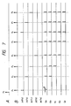
- the timing for generating the strobe pulses S1, S2, S3, ... is usually set so that they are delayed behind the generation of the timing pulses P1, P2, P3, ... for periods K1, K2, K3, ..., respectively, which are shorter than the corresponding periods of the time intervals A1, A2, A3, ... at which the test patterns are produced, as shown in Figs. 2A and 2B.
- the flag "NEXT" is set and the delay time M1 is defined relative to the beginning of the next period, and consequently, the allowable delay time is limited only to the range of the next period. It is therefore impossible, with this prior art, to test a device which outputs a response signal after as much delay as several cycles of the timing pulse, such as a central processor.
- the document US-A-4,553,100 discloses a strobe pulse generator for generating strobe pulses in response to timing pulses.
- an address counter is preset by each timing pulse and counts clock pulses until the next timing pulse.
- a mark memory in which marks representative of a delay time are stored, is addressed by the address from the address counter. If a mark is stored at the address designated by the counter, a strobe pulse will be generated.
- the delay time between a timing pulse and a subsequent strobe pulse is an integer multiple of the clock period and less than the period of the timing pulses since the address counter is reset by each timing pulse.
- the timing pulses are divided into two or more groups and a corresponding number of units each including a clock generator, an address counter, a mark memory and gate circuits has to be provided.
- a corresponding number of units each including a clock generator, an address counter, a mark memory and gate circuits.
- the period data is cumulatively subtracted from the delay data, and upon detecting the inversion of the sign of the computed value, the cycle of the timing signal in which to produce a delayed pulse is defined.
- the immediately preceding cycle is utilized as delay data so that a pulse is produced which is delayed by the value of the delay data relative to the beginning of the next pattern generation cycle. Accordingly, even if the delay data is set to a value containing a plurality of pattern generating cycles, delayed pulses can be produced at preset timing. Consequently, strobe pulses can be generated for testing a device which yields a response signal several cycles after the beginning of the pattern generating cycle.
- Fig. 4 illustrates in block form an embodiment of the timing generator of the present invention.
- This embodiment includes: a period data memory 21 in which there are prestored period data A1, A2, A3, ... for test pattern signals which are provided to a DUT; a delay data memory 22 in which there are prestored delay data K1, K2, K3, ... corresponding to the period data; a pulse generator 24 which generates timing pulses P1, P2, P3, ... for determining the timing for the application of test patterns to the DUT on the basis of the period data read out of the memory 21; a computing section 25 which computes the timing for the generation of delayed strobe pulses S1, S2, S3, ... on the basis of the period data A1, A2, A3, ...
- a controller 23 which generates read addresses for the memories 21 and 22 and control signals for the calculator 25; and a delayed pulse generator 26 which outputs the strobe pulses S1, S2, S3, ... delayed in accordance with delay data computed by the computing section 25.
- the controller 23 includes an address counter 23A which counts the timing pulses P1, P2, P3, ... provided from the pulse generator 24 and applies the count value as a readout address to each of the memories 21 and 22, a delay element 23B which delays each of the timing pulses P1, P2, P3, ... for a fixed time and outputs it as a control signal G, a D-type flip-flop 23C and a gate 23D for generating a control signal F corresponding to the timing pulse to be delayed, and an oscillator (not shown) for generating clock pulses CLK of a fixed period.
- an address counter 23A which counts the timing pulses P1, P2, P3, ... provided from the pulse generator 24 and applies the count value as a readout address to each of the memories 21 and 22, a delay element 23B which delays each of the timing pulses P1, P2, P3, ... for a fixed time and outputs it as a control signal G, a D-type flip-flop 23C and a gate 23D for generating a control signal F corresponding to
- the computing section 25 includes a subtractor 25A which subtracts the period data A1, A2, A3, ... input to its one input D2, from a value input to the other input D1, and provides the difference value and its sign (indicated by "H" when it is minus) to output terminals X and B, respectively, a multiplexer 25B which selectively outputs either one of the delay data K1, K2, K3, ...
- a latch circuit 25C which holds the output of the multiplexer 25B and applies it to the input D1 of the subtractor 25A and the delayed pulse generator 26, and a gate 25E and a delay element 25G for providing the control signal F or G from the controller 23, as a latch signal H, to the delayed pulse generator 26.
- the delayed pulse generator 26 responds to the latch signal H to latch in a latch circuit 26A timing data supplied from the computing section 25, compares the contents of the latch circuit 26A and a counter 26B by a comparator 26C and, upon each detection of coincidence between them, yields the strobe pulses S1, S2, S3, ...
- the counter 26B counts upward high-frequency clock pulses CLK of a fixed period which are always provided from the controller 23 to a clock terminal CK of the counter 26B, and its count value is reset to zero by the latch signal H.
- the pulse generator 24 may be of the same construction as that of the delayed pulse generator 26 but may also be of an arrangement which employs a down-counter instead of using a comparator, counts clock pulses down when delay data is preset in the down-counter, and generates a pulse when the counter has reached a zero count.
- a start pulse Ps is applied to the controller 23 and the pulse generator 24 to initialize them.
- the pulse generator 24 responds to the start pulse Ps to generate a first timing pulse P1 shown in Fig. 5B and thereafter, upon each application thereto of the period data A1, A2, A3, ... read out of the memory 21, generates the timing pulses P2, P3, ... in succession at time intervals specified by these data.
- the flip-flop 23C is set by the start pulse Ps and its Q output goes high “H” as depicted in Fig. 5Q, enabling the gate 23D and P1 is provided as the control signal F.
- the timing pulse P1 is also delayed by the delay element 23B and then is applied to a clock terminal CK of the flip-flop 23C, which loads therein a low "L” level of the signal E, causing its Q output to go low “L” and hence disable the gate 23D.
- the address counter 23A is stepped one stage after responding to the first timing pulse P1 to provide its contents as a first address, for example, "0000", to each of the memories 21 and 22, from which the period data A1 and the corresponding delay data K1 are read out, respectively.
- the control signal F is being applied to a selective control terminal SEL of the multiplexer 25B and its output terminal Y is connected to its input D1. Consequently, the delay data K1 read out of the memory 22 is provided via the multiplexer 25B to an input terminal D of the latch circuit 25C, wherein the data K1 is latched by a latch signal provided thereto via a gate 25F.
- the data K1 thus latched is provided to the one input terminal D1 of the subtractor 25A and a difference K1 - A1 between it and the period data A1 supplied to the other input terminal D2 is provided to an output terminal X.
- the multiplexer 25B immediately connects its input terminal D2 to the output Y, and consequently, the difference value K1 - A1 is applied to and latched in the latch circuit 25C by the delayed control signal G provided thereto via the gates 25D and 25E.
- the control signal G is not applied to the latch circuit 26A and the value K1 - A1 latched in the latch circuit 25C is not provided to the latch circuit 26A.
- the pulse generator 24 yields, as shown in Fig. 5B, the timing pulse P2 a time A1 after the generation of the timing pulse P1 in accordance with the period data A1.
- the controller 23 responds to the pulse P2 to provide the next addresses to the memories 21 and 22 to read out therefrom the data K2 and A2, respectively.
- the subtractor 25A subtracts A2 from the output K1 - A1 of the latch circuit 25C and outputs the difference.
- the multiplexer 25B since the multiplexer 25B is not being supplied with the control signal F, its input terminal D2 connected to the output terminal Y and the subtracted output (K1 - A1) - A2 of the subtractor 25A is provided via the multiplexer 25B to the latch circuit 25C.
- the timing generator performs the same operations as those described above in connection with the timing pulse P2, latching a cumulatively subtracted value (K1 - A1 - A2) - A3 in the latch circuit 25C.
- the pulse generator 24 yields the timing pulse P4
- the period data A4 is read out of the memory 21 in accordance with the address which is provided from the controller 23 in response to the timing pulse P4 and the subtractor 25A performs a computation (K1 - A1 - A2 - A3) - A4 . Since the cumulatively subtracted output is minus in sign, an "H" signal is provided to the sign output terminal B, disabling the gate 25D and enabling the gate 25E.
- the control signal G is not applied to the latch circuit 25C, in which the previous value ( K1 - A1 - A2 - A3 ) is held intact.
- the control signal G is provided via the gate 25E to the latch circuit 26A of the delayed pulse generator 26, the value ( K1 - A1 - A2 - A3 ) is latched in the latch circuit 26A, and at the same time, the counter 26B is reset to count the clock pulses CLK from zero upward.
- the comparator 26C compares the output of the latch circuit 26A and the output of the counter 26B and, upon detection of coincidence therebetween, yields a pulse. Accordingly, the delayed pulse generator 26 outputs, as a strobe pulse, a pulse delayed substantially for the time ( K1 - A1 - A2 - A3 ) relative to the timing pulse P4.
- the controller 23 when supplied with the timing pulse P5 from the pulse generator 24, the controller 23 yields the control signal F to read out data K5 and A5 from the memories 21 and 22, respectively. If K5 - A5 > 0 , then the output signal E at the sign output terminal B of the subtractor 25A goes low "L” as depicted in Fig. 5E, enabling the gate 25D and disabling the gate 25E. Thus the same operations as those mentioned above in connection with the data K1 are conducted. If K5 - A5 ⁇ 0 , then the sign output signal E of the subtractor 25A remains high "H" during the period of the data A5 and the control signal G provided in response to the timing pulse P5 is applied as the latch signal H (not shown in Fig.
- the delay data K5 latched in the latch circuit 25C by the control signal F provided in response to the timing pulse P5 is input into the latch circuit 26A and the delayed pulse generator 26 generates a delayed strobe pulse (not shown in Fig. 5C) about the time K5 after the generation of the timing pulse P5.
- Fig. 6 illustrates another embodiment of the timing generator of the present invention which is capable of generating strobe pulses delayed as desired corresponding to all timing pulses produced.
- the computing sections 25a to 25e each include a latch circuit 25I, through which the delay data K1, K2, K3, ... read out of the memory 22 are provided to the input terminal D1 of the multiplexer 25B.
- the computing sections 25a to 25e are almost identical in construction with the computing section 25 in Fig. 4 except the above.
- the delay data read out of the memory 22 are provided to the latch circuits 25 of the computing section 25a through 25e in commen to them, and latch signals Ja through Je for loading the data into the latch circuits 25I are provided from the controller 23 respectively corresponding to the timing pulses P1, P2, P3, ... from the pulse generator 24 as depicted in Figs. 7Ja to 7Je.
- latch signals Ja to Je the delay data are latched in the latch circuits 25 of the computing sections 25a to 25e in a cyclic order.
- the period data A1, A2, A3, ... read out of the memory 21 are provided to the computing sections 25a through 25e in common to them.
- the computing section 25a is supplied with control signals Ga produced in response to the first and subsequent timing pulses P1, P2, P3, ... after the generation of the start pulse Ps as shown in Fig. 7Ga, by which the outputs of the multiplexer 25B are sequentially latched in the latch circuit 25C.
- the computing section 25b is supplied with control signals Gb corresponding to the second and subsequent timing pulses P2, P3, P4, ... as shown in Fig. 7Gb, by which the outputs of the multiplexer 25B corresponding to the second and subsequent timing pulses P2, P3, ... are latched in the latch circuit 25C.
- the computing section 25c is supplied with control signals Gc corresponding to the timing pulses P3, P4, P5, ... as shown in Fig.
- the controller 23 includes, as shown in Fig. 8, an address counter 23A which counts timing pulses and generates an address, a quinary counter 23E for counting the timing pulses, a decoder 23F which decodes the count value of the quinary counter 23E and provides pulses to five output terminals in a sequential order, flip-flops 23G which respond to the outputs of the decoder 23F to cause their Q outputs to go high "H" in a cyclic order, gates 23H which are enabled by the Q outputs to pass therethrough the timing pulses, and an oscillator 23K which produces clock pulses CLK of a fixed period.
- the start pulse Ps is applied to reset terminals of the address counter 23A, the quinary counter 23E and the flip-flops 23G to reset them to their initial state.
- the quinary counter 23E is a counter which is reset to zero upon each counting of five timing pulses and its count value is decoded by the decoder 23F, from which the control signals Ja to Je are provided one by one to five output terminals in a cyclic order as shown in Figs. 7Ja to 7Je.
- These control signals are also used as control signals Fa to Fe, but in this case, since the timing for latching of the latch circuit 25 needs to precede the timing for latching of the latch circuit 25C at all times, the circuit pattern is designed so that the control signals Fa to Fe are slightly delayed behind the control signals Ja to Je.
- the outputs of the decoder 23F are also applied to the flip-flops 23G to make their Q outputs high "H" in a sequential order, enabling the gates 23H one after another.
- the timing pulses P1, P2, P3, ... are output, via the gates 23H, as the control signals Ga through Ge shown in Figs. 76a to 7Ge.
- the computing sections 25a to 25e can provide a delay of up to four cycles with respect to the timing pulse corresponding to the applied delay data.
- the operations of the computing sections 25a to 25e and the corresponding delayed pulse generators 26a to 26e are substantially the same as those described previously in connection with the embodiment shown in Fig. 4, and hence no description will be given of their operations.
- the outputs of the delayed pulse generators 26a to 26e are output as the strobe pulses S1, S2, S3, ... via an OR circuit 27.
- the timing generator of the present invention employs an arrangement in which the delay data is cumulatively subtracted using the period data, it is determined, by the detection of inversion of the sign of the computed value, that the cycle in which to generate a delayed pulse has been reached, and the delayed pulse is generated at the time point elapsed after the beginning of the cycle by the value of the delay data obtained as the above-said cumulatively subtracted value, and consequently, it is possible to accurately produce delayed pulses even if the delay time is as long as several cycles of the period data. Accordingly, the timing generator of the present invention permits testing of a device which outputs a response signal several cycles after the application of a test pattern, such as a central processor. In addition, the timing generator does not utilize, for creating delayed pulses, a microcomputer which operates under program control, and hence it is capable of generating timing pulses of high throughput.
Landscapes
- Physics & Mathematics (AREA)
- Engineering & Computer Science (AREA)
- General Engineering & Computer Science (AREA)
- General Physics & Mathematics (AREA)
- Nonlinear Science (AREA)
- Tests Of Electronic Circuits (AREA)
- Dram (AREA)
Description
- The present invention relates to a device for generating strobe pulses at desired timing, which can be used in an IC tester, for example.
- The IC tester comprises, as shown in Fig. 1, a
timing generator 11, apattern generator 12 which generates test pattern signals in response to timing signals P₁, P₂, P₃, ... from thetiming generator 11, aformatter 13 which converts the test pattern signals from thetest pattern generator 12 into a real waveform for input into a device under test (hereinafter referred to simply as DUT) 14, adata latch circuit 15 which latches a response output signal from theDUT 14, and alogic comparator 16 which compares the response output signal latched in thedata latch circuit 15 and an expected value pattern from thepattern generator 12 to determine whether theDUT 14 is good or not. - In the
timing generator 11 there are preset period data A₁, A₂, A₃, ... for defining the time intervals at which the test pattern signals are generated and delay data K₁, K₂, K₃, ... which correspond to the period data A₁, A₂, A₃, ..., respectively. When supplied with a start pulse Ps from the outside, thetiming generator 11 outputs the timing signals P₁, P₂, P₃, ... at the time intervals defined by the period data A₁, A₂, A₃, ..., and thepattern generator 12 yields the test pattern signals in response to the timing signals P₁, P₂, P₃, ... - The delay data K₁, K₂, K₃, ... are timed to the generation of response output signals which are provided from the
DUT 14 supplied with test patterns in accordance with the timing signals P₁, P₂, P₃, ... At the timing set by thetiming generator 11 in dependence on the delay data K₁, K₂, K₃, ... strobe pulses S₁, S₂, S₃, ... are generated and applied to thelatch circuit 15. - The timing for generating the strobe pulses S₁, S₂, S₃, ... is usually set so that they are delayed behind the generation of the timing pulses P₁, P₂, P₃, ... for periods K₁, K₂, K₃, ..., respectively, which are shorter than the corresponding periods of the time intervals A₁, A₂, A₃, ... at which the test patterns are produced, as shown in Figs. 2A and 2B. However, there are times, for example, as depicted in Figs. 3A and 3B, when the strobe pulse S₁ is to be generated in the next period as a result of setting the period data A₁ to a shorter period of time. In such an instance, it is customary in the prior art to employ a method in which a flag "NEXT" is set for the delay data K₁, a calculation

- According to the prior art in the case of generating each of the strobe pulses S₁, S₂, S₃, ... at the timing beyond the limits of the corresponding period, the flag "NEXT" is set and the delay time M₁ is defined relative to the beginning of the next period, and consequently, the allowable delay time is limited only to the range of the next period. It is therefore impossible, with this prior art, to test a device which outputs a response signal after as much delay as several cycles of the timing pulse, such as a central processor.
- The document US-A-4,553,100 discloses a strobe pulse generator for generating strobe pulses in response to timing pulses. In this prior art an address counter is preset by each timing pulse and counts clock pulses until the next timing pulse. A mark memory in which marks representative of a delay time are stored, is addressed by the address from the address counter. If a mark is stored at the address designated by the counter, a strobe pulse will be generated. In this case, the delay time between a timing pulse and a subsequent strobe pulse is an integer multiple of the clock period and less than the period of the timing pulses since the address counter is reset by each timing pulse. According to this prior art, for obtaining a strobe pulse delayed beyond the next timing pulse, the timing pulses are divided into two or more groups and a corresponding number of units each including a clock generator, an address counter, a mark memory and gate circuits has to be provided. Thus, the higher the number of periods of the timing pulses by which a strobe pulse is desired to be delayed, the larger the circuit becomes.
- It is therefore an object of the present invention to provide a timing generator which permits the generation of strobe pulses to be delayed for a desired number of cycles of the timing signal.
- This object is achieved with a device as claimed in
claim 1. - Specific embodiments of the invention are subject-matter of dependent claims.
- According to the present invention, the period data is cumulatively subtracted from the delay data, and upon detecting the inversion of the sign of the computed value, the cycle of the timing signal in which to produce a delayed pulse is defined. In the cycle thus defined by the result of computation, the immediately preceding cycle is utilized as delay data so that a pulse is produced which is delayed by the value of the delay data relative to the beginning of the next pattern generation cycle. Accordingly, even if the delay data is set to a value containing a plurality of pattern generating cycles, delayed pulses can be produced at preset timing. Consequently, strobe pulses can be generated for testing a device which yields a response signal several cycles after the beginning of the pattern generating cycle.
-
- Fig. 1 is a block diagram showing the general arrangement of a conventional IC tester;
- Figs. 2A and 2B are timing charts showing the relationship between timing pulses and strobe pulses delayed for a time shorter than one cycle thereof;
- Figs. 3A and 3B are timing charts showing the relationship between timing pulses and strobe pulse delayed for a time longer than one cycle thereof;
- Fig. 4 is a block diagram illustrating an embodiment of the timing generator of the present invention;
- Fig. 5 is a timing chart for explaining the operation of the embodiment depicted in Fig. 4;
- Fig. 6 is a block diagram illustrating a second embodiment of the present invention;
- Fig. 7 is a timing chart for explaining various control signals in the embodiment depicted in Fig. 6; and
- Fig. 8 is a block diagram illustrating an example of a
controller 23 used in the embodiment shown in Fig. 6. - Fig. 4 illustrates in block form an embodiment of the timing generator of the present invention. This embodiment includes: a
period data memory 21 in which there are prestored period data A₁, A₂, A₃, ... for test pattern signals which are provided to a DUT; adelay data memory 22 in which there are prestored delay data K₁, K₂, K₃, ... corresponding to the period data; apulse generator 24 which generates timing pulses P₁, P₂, P₃, ... for determining the timing for the application of test patterns to the DUT on the basis of the period data read out of thememory 21; acomputing section 25 which computes the timing for the generation of delayed strobe pulses S₁, S₂, S₃, ... on the basis of the period data A₁, A₂, A₃, ... and the delay data K₁, K₂, K₃, ... read out of thememories controller 23 which generates read addresses for thememories calculator 25; and adelayed pulse generator 26 which outputs the strobe pulses S₁, S₂, S₃, ... delayed in accordance with delay data computed by thecomputing section 25. - The
controller 23 includes anaddress counter 23A which counts the timing pulses P₁, P₂, P₃, ... provided from thepulse generator 24 and applies the count value as a readout address to each of thememories delay element 23B which delays each of the timing pulses P₁, P₂, P₃, ... for a fixed time and outputs it as a control signal G, a D-type flip-flop 23C and a gate 23D for generating a control signal F corresponding to the timing pulse to be delayed, and an oscillator (not shown) for generating clock pulses CLK of a fixed period. - The
computing section 25 includes asubtractor 25A which subtracts the period data A₁, A₂, A₃, ... input to its one input D₂, from a value input to the other input D₁, and provides the difference value and its sign (indicated by "H" when it is minus) to output terminals X and B, respectively, amultiplexer 25B which selectively outputs either one of the delay data K₁, K₂, K₃, ... from thememory 22 and the difference value from thesubtractor 25A in accordance with the control signal F from thecontroller 23, alatch circuit 25C which holds the output of themultiplexer 25B and applies it to the input D₁ of thesubtractor 25A and thedelayed pulse generator 26, and agate 25E and adelay element 25G for providing the control signal F or G from thecontroller 23, as a latch signal H, to thedelayed pulse generator 26. - The
delayed pulse generator 26 responds to the latch signal H to latch in alatch circuit 26A timing data supplied from thecomputing section 25, compares the contents of thelatch circuit 26A and acounter 26B by acomparator 26C and, upon each detection of coincidence between them, yields the strobe pulses S₁, S₂, S₃, ... Thecounter 26B counts upward high-frequency clock pulses CLK of a fixed period which are always provided from thecontroller 23 to a clock terminal CK of thecounter 26B, and its count value is reset to zero by the latch signal H. Thepulse generator 24 may be of the same construction as that of thedelayed pulse generator 26 but may also be of an arrangement which employs a down-counter instead of using a comparator, counts clock pulses down when delay data is preset in the down-counter, and generates a pulse when the counter has reached a zero count. - Turning next to the timing chart of Fig. 5, the operation of the timing generator shown in Fig. 4 will be described. At the time point shown in Fig. 5A a start pulse Ps is applied to the
controller 23 and thepulse generator 24 to initialize them. Thepulse generator 24 responds to the start pulse Ps to generate a first timing pulse P₁ shown in Fig. 5B and thereafter, upon each application thereto of the period data A₁, A₂, A₃, ... read out of thememory 21, generates the timing pulses P₂, P₃, ... in succession at time intervals specified by these data. - On the other hand, the flip-
flop 23C is set by the start pulse Ps and its Q output goes high "H" as depicted in Fig. 5Q, enabling the gate 23D and P₁ is provided as the control signal F. The timing pulse P₁ is also delayed by thedelay element 23B and then is applied to a clock terminal CK of the flip-flop 23C, which loads therein a low "L" level of the signal E, causing its Q output to go low "L" and hence disable the gate 23D. - The
address counter 23A is stepped one stage after responding to the first timing pulse P₁ to provide its contents as a first address, for example, "0000", to each of thememories multiplexer 25B and its output terminal Y is connected to its input D₁. Consequently, the delay data K₁ read out of thememory 22 is provided via themultiplexer 25B to an input terminal D of thelatch circuit 25C, wherein the data K₁ is latched by a latch signal provided thereto via agate 25F. The data K₁ thus latched is provided to the one input terminal D₁ of thesubtractor 25A and a difference K₁ - A₁ between it and the period data A₁ supplied to the other input terminal D₂ is provided to an output terminal X. - In the example described above with respect to Fig. 5 the value of the delay data K₁ selected greater than three cycles of the timing pulse but smaller than four cycles, that is, intermediate between the pulses P₄ and P₅ in Fig. 5B. Accordingly,

subtractor 25A is "L", so that a gate 25D is held enabled but thegate 25E is held disabled. When the control signal F falls, themultiplexer 25B immediately connects its input terminal D₂ to the output Y, and consequently, the difference value K₁ - A₁ is applied to and latched in thelatch circuit 25C by the delayed control signal G provided thereto via thegates 25D and 25E. In this instance, since thegate 25E remains disabled, the control signal G is not applied to thelatch circuit 26A and the value K₁ - A₁ latched in thelatch circuit 25C is not provided to thelatch circuit 26A. - On the other hand, the
pulse generator 24 yields, as shown in Fig. 5B, the timing pulse P₂ a time A₁ after the generation of the timing pulse P₁ in accordance with the period data A₁. Thecontroller 23 responds to the pulse P₂ to provide the next addresses to thememories subtractor 25A subtracts A₂ from the output K₁ - A₁ of thelatch circuit 25C and outputs the difference. At this time, since themultiplexer 25B is not being supplied with the control signal F, its input terminal D₂ connected to the output terminal Y and the subtracted output

subtractor 25A is provided via themultiplexer 25B to thelatch circuit 25C. Since

controller 23 in response to the pulse P₂ is applied via thegates 25D and 25F to the clock terminal CK of thelatch circuit 25C to latch therein the value
- Also in response to the timing pulse P₃ the timing generator performs the same operations as those described above in connection with the timing pulse P₂, latching a cumulatively subtracted value

latch circuit 25C. When thepulse generator 24 yields the timing pulse P₄, the period data A₄ is read out of thememory 21 in accordance with the address which is provided from thecontroller 23 in response to the timing pulse P₄ and thesubtractor 25A performs a computation
gate 25E. Consequently, the control signal G is not applied to thelatch circuit 25C, in which the previous value (
gate 25E to thelatch circuit 26A of the delayedpulse generator 26, the value (

latch circuit 26A, and at the same time, thecounter 26B is reset to count the clock pulses CLK from zero upward. Thecomparator 26C compares the output of thelatch circuit 26A and the output of thecounter 26B and, upon detection of coincidence therebetween, yields a pulse. Accordingly, the delayedpulse generator 26 outputs, as a strobe pulse, a pulse delayed substantially for the time (
- Next, when supplied with the timing pulse P₅ from the
pulse generator 24, thecontroller 23 yields the control signal F to read out data K₅ and A₅ from thememories 
subtractor 25A goes low "L" as depicted in Fig. 5E, enabling the gate 25D and disabling thegate 25E. Thus the same operations as those mentioned above in connection with the data K₁ are conducted. If
subtractor 25A remains high "H" during the period of the data A₅ and the control signal G provided in response to the timing pulse P₅ is applied as the latch signal H (not shown in Fig. 5H) to the delayedpulse generator 26 via thegate 25E and thedelay element 25G. AS a result of this, the delay data K₅ latched in thelatch circuit 25C by the control signal F provided in response to the timing pulse P₅ is input into thelatch circuit 26A and the delayedpulse generator 26 generates a delayed strobe pulse (not shown in Fig. 5C) about the time K₅ after the generation of the timing pulse P₅. - As will be appreciated from the above, in the embodiment shown in Fig. 4, for example, when the strobe pulse S₁ produced which is delayed for a time longer than one cycle relative to the generated timing pulse P₁, no strobe pulses will be produced corresponding to the timing pulses P₂, P₃ and P₄ which have been provided until the generation of the strobe pulse S₁, and after the generation of the timing pulse P₅, corresponding strobe pulses can be produced.
- Fig. 6 illustrates another embodiment of the timing generator of the present invention which is capable of generating strobe pulses delayed as desired corresponding to all timing pulses produced. In this embodiment there are provided pairs of
computing sections 25 and delayedpulse generators 26 of the same number as a predicted maximum number of delay cycles, five in this case. Thecomputing sections 25a to 25e each include a latch circuit 25I, through which the delay data K₁, K₂, K₃, ... read out of thememory 22 are provided to the input terminal D₁ of themultiplexer 25B. Thecomputing sections 25a to 25e are almost identical in construction with thecomputing section 25 in Fig. 4 except the above. - The delay data read out of the
memory 22 are provided to thelatch circuits 25 of thecomputing section 25a through 25e in commen to them, and latch signals Ja through Je for loading the data into the latch circuits 25I are provided from thecontroller 23 respectively corresponding to the timing pulses P₁, P₂, P₃, ... from thepulse generator 24 as depicted in Figs. 7Ja to 7Je. By these latch signals Ja to Je the delay data are latched in thelatch circuits 25 of thecomputing sections 25a to 25e in a cyclic order. On the other hand, the period data A₁, A₂, A₃, ... read out of thememory 21 are provided to thecomputing sections 25a through 25e in common to them. Thecomputing section 25a is supplied with control signals Ga produced in response to the first and subsequent timing pulses P₁, P₂, P₃, ... after the generation of the start pulse Ps as shown in Fig. 7Ga, by which the outputs of themultiplexer 25B are sequentially latched in thelatch circuit 25C. Thecomputing section 25b is supplied with control signals Gb corresponding to the second and subsequent timing pulses P₂, P₃, P₄, ... as shown in Fig. 7Gb, by which the outputs of themultiplexer 25B corresponding to the second and subsequent timing pulses P₂, P₃, ... are latched in thelatch circuit 25C. Similarly, the computing section 25c is supplied with control signals Gc corresponding to the timing pulses P₃, P₄, P₅, ... as shown in Fig. 5Gc, by which the outputs of themultiplexer 25B corresponding to such timing pulses are latched in thelatch circuit 25C. This applies to thecomputing sections 25d and 25e. The contents of thelatch circuits 25C of thecomputing sections 25a to 25e are provided to thelatch circuits 26A of the corresponding delayedpulse generators 26a to 26e and strobe pulses are produced on the basis of the values sequentially latched therein by the latch signals H in the same manner as in the embodiment depicted in Fig. 4. - The
controller 23 includes, as shown in Fig. 8, anaddress counter 23A which counts timing pulses and generates an address, aquinary counter 23E for counting the timing pulses, adecoder 23F which decodes the count value of thequinary counter 23E and provides pulses to five output terminals in a sequential order, flip-flops 23G which respond to the outputs of thedecoder 23F to cause their Q outputs to go high "H" in a cyclic order,gates 23H which are enabled by the Q outputs to pass therethrough the timing pulses, and an oscillator 23K which produces clock pulses CLK of a fixed period. The start pulse Ps is applied to reset terminals of theaddress counter 23A, thequinary counter 23E and the flip-flops 23G to reset them to their initial state. - The
quinary counter 23E is a counter which is reset to zero upon each counting of five timing pulses and its count value is decoded by thedecoder 23F, from which the control signals Ja to Je are provided one by one to five output terminals in a cyclic order as shown in Figs. 7Ja to 7Je. These control signals are also used as control signals Fa to Fe, but in this case, since the timing for latching of thelatch circuit 25 needs to precede the timing for latching of thelatch circuit 25C at all times, the circuit pattern is designed so that the control signals Fa to Fe are slightly delayed behind the control signals Ja to Je. The outputs of thedecoder 23F are also applied to the flip-flops 23G to make their Q outputs high "H" in a sequential order, enabling thegates 23H one after another. The timing pulses P₁, P₂, P₃, ... are output, via thegates 23H, as the control signals Ga through Ge shown in Figs. 76a to 7Ge. - With the arrangement depicted in Fig. 6, the
computing sections 25a to 25e can provide a delay of up to four cycles with respect to the timing pulse corresponding to the applied delay data. The operations of thecomputing sections 25a to 25e and the corresponding delayedpulse generators 26a to 26e are substantially the same as those described previously in connection with the embodiment shown in Fig. 4, and hence no description will be given of their operations. The outputs of the delayedpulse generators 26a to 26e are output as the strobe pulses S₁, S₂, S₃, ... via an ORcircuit 27. - As described above, the timing generator of the present invention employs an arrangement in which the delay data is cumulatively subtracted using the period data, it is determined, by the detection of inversion of the sign of the computed value, that the cycle in which to generate a delayed pulse has been reached, and the delayed pulse is generated at the time point elapsed after the beginning of the cycle by the value of the delay data obtained as the above-said cumulatively subtracted value, and consequently, it is possible to accurately produce delayed pulses even if the delay time is as long as several cycles of the period data. Accordingly, the timing generator of the present invention permits testing of a device which outputs a response signal several cycles after the application of a test pattern, such as a central processor. In addition, the timing generator does not utilize, for creating delayed pulses, a microcomputer which operates under program control, and hence it is capable of generating timing pulses of high throughput.
Claims (5)
- A device for generating strobe pulses at desired timing including:
timing pulse generating means (24) which starts generation of timing pulses (P₁, P₂, P₃) in response to a start pulse (Ps) applied thereto;
address generating means (23) which responds to each of said timing pulses from said timing pulse generating means to generate an address (AD);
a period data memory (21) for reading out therefrom period data (A₁-A₄) upon each reception of an address from said address generating means, each said period data defining the timing for generation of the next timing pulse, said timing pulse generating means generating the timing pulses at intervals indicated by the period data supplied thereto from said period data memory;
a delay data memory (22) for reading out therefrom delay data (K₁-K₄) upon reception of the address from said address generating means, each of said delay data defining a delay length relative to a corresponding one of the timing pulses;
computing means (25) which receives the period data from said period data memory and the delay data from said delay data memory, and upon each reception of the period data, cumulatively subtracts the period data from one of the delay data until the sign of the subtraction result changes; and
strobe pulse generating means (26) which receives the subtraction result from said computing means and, upon change in the sign of the subtraction result to negative, loads thereinto the immediately preceding subtraction result indicating a delay value and generates a strobe pulse delayed by the loaded delay value behind the timing pulse which has caused the change in the sign of the subtraction result. - The device according to claim 1, wherein said computing means (25) includes:
subtracting means (25A) supplied at one of the two inputs thereof with the period data from said period data memory (21), for subtracting the period data from data supplied to the other input and outputting a subtracted value (D) and its sign (E);
multiplexer means (25B) which is supplied with said subtracted value from said subtracting means and said delay data read out of said delay data memory (22) and selectively outputs one of these inputs;
latch means (25C) for latching the output from said multiplexer means, the output of said latch means being supplied to said other input of said subtracting means and supplied, as the computed value from said computing means, to said strobe pulse generating means (26);
wherein said device further comprises control means (23B, 23C, 23D) supplied with the timing pulses for providing a selection signal (F) to said multiplexer means (25B) to select the delay data from said delay data memory in response to the timing pulse immediately following said start pulse and each timing pulse immediately following a timing pulse which has rendered the subtraction results to a negative value and, otherwise, to select the subtracted value from said subtracting means. - The device of claim 1, wherein said computing means (25) and said strobe pulse generating means (26) include a plurality of computing sections (25a-25e) and a plurality of strobe pulse generators (26a-26e), respectively.
- The device according to claim 3, wherein said device further comprises control means (23E, 23F) which responds to each of said timing pulse to generate a control signal (Ja-Je) for respectively loading said delay data read out of said delay data memory (22) into said computing sections (25a-25e) in a sequential, cyclic order.
- The device according to claim 4, wherein each of said computing sections (25a-25e) includes:
first latch means (25I) which responds to said loading control signal (Ja-Je) to latch said delay data from said delay data memory;
subtracting means (25A) supplied at one of the two inputs thereof with the period data from said period data memory (21) for subtracting the period data from data supplied to the other input and outputting a subtracted value and its sign;
multiplexer means (25B) which is supplied with said subtracted value from said subtracting means and the output of said first latch means and outputs either one of them in accordance with a selection control signal (Fa-Fe); and
second latch means (25C) for latching the output value from said multiplexer means, the output of said second latch means being supplied to the other input of said subtracting means and, as the computed value, to said strobe generating means (26a-26e);
wherein said control means further comprises selection control signal generating means (23E, 23F) supplied with the timing pulses for providing said selection control signal (Fa-Fe) to said multiplexer means (25B) to select the delay data from said delay data memory in response to the timing pulse immediately following said start pulse and each timing pulse immediately following a timing pulse which has rendered the subtraction result to a negative value and, otherwise, to select the subtracted value from said subtracting means.
Applications Claiming Priority (2)
| Application Number | Priority Date | Filing Date | Title |
|---|---|---|---|
| JP126597/88 | 1988-05-23 | ||
| JP63126597A JP2719684B2 (en) | 1988-05-23 | 1988-05-23 | Delay generator |
Publications (3)
| Publication Number | Publication Date |
|---|---|
| EP0343537A2 EP0343537A2 (en) | 1989-11-29 |
| EP0343537A3 EP0343537A3 (en) | 1990-05-23 |
| EP0343537B1 true EP0343537B1 (en) | 1994-03-16 |
Family
ID=14939127
Family Applications (1)
| Application Number | Title | Priority Date | Filing Date |
|---|---|---|---|
| EP89109091A Expired - Lifetime EP0343537B1 (en) | 1988-05-23 | 1989-05-19 | Timing generator |
Country Status (4)
| Country | Link |
|---|---|
| US (1) | US4998025A (en) |
| EP (1) | EP0343537B1 (en) |
| JP (1) | JP2719684B2 (en) |
| DE (1) | DE68913807T2 (en) |
Families Citing this family (20)
| Publication number | Priority date | Publication date | Assignee | Title |
|---|---|---|---|---|
| US5321702A (en) * | 1989-10-11 | 1994-06-14 | Teradyne, Inc. | High speed timing generator |
| JP2915945B2 (en) * | 1990-01-12 | 1999-07-05 | 株式会社アドバンテスト | Memory test equipment |
| JPH0816857B2 (en) * | 1990-07-20 | 1996-02-21 | 富士通株式会社 | Clock controller |
| US5212443A (en) * | 1990-09-05 | 1993-05-18 | Schlumberger Technologies, Inc. | Event sequencer for automatic test equipment |
| US5225772A (en) * | 1990-09-05 | 1993-07-06 | Schlumberger Technologies, Inc. | Automatic test equipment system using pin slice architecture |
| US5293080A (en) * | 1990-10-09 | 1994-03-08 | Hewlett-Packard Company | Method and apparatus for generating test waveforms to be applied to a device under test |
| FR2684208B1 (en) * | 1990-10-30 | 1995-01-27 | Teradyne Inc | CIRCUIT FOR PROVIDING PERIOD INFORMATION. |
| EP0491998B1 (en) * | 1990-12-28 | 1996-07-24 | International Business Machines Corporation | Programme-controlled method and circuit arrangement for generating pulses within successive time intervals |
| FR2671261B1 (en) * | 1991-01-04 | 1993-04-02 | Tecnoma | APPARATUS FOR TREATING THE SOIL OR VEGETATION, INCLUDING A RAMP WHICH CAN PIVOT WITH RESPECT TO LONGITUDINAL AND TRANSVERSAL AXES. |
| US5272390A (en) * | 1991-09-23 | 1993-12-21 | Digital Equipment Corporation | Method and apparatus for clock skew reduction through absolute delay regulation |
| US5321315A (en) * | 1992-03-09 | 1994-06-14 | Eastman Kodak Company | Tracking control pulse generation for variable frame rate CCD sensors for electronic imaging applications |
| CA2127192C (en) * | 1993-07-01 | 1999-09-07 | Alan Brent Hussey | Shaping ate bursts, particularly in gallium arsenide |
| EP0686917A1 (en) * | 1994-06-07 | 1995-12-13 | International Business Machines Corporation | Apparatus for processing a series of timing signals |
| US5867050A (en) * | 1995-12-28 | 1999-02-02 | Ando Electric Co., Ltd. | Timing generator circuit |
| GB9910943D0 (en) | 1999-05-11 | 1999-07-14 | Sgs Thomson Microelectronics | Response time measurement |
| DE10393883T5 (en) * | 2002-12-13 | 2005-11-17 | Advantest Corp. | Timing generating circuit and the semiconductor test apparatus having the timing generation circuit |
| KR100590204B1 (en) * | 2003-11-04 | 2006-06-15 | 삼성전자주식회사 | Integrated circuit device with on-chip setup / hold measurement circuit |
| GB0413146D0 (en) * | 2004-06-12 | 2004-07-14 | Texas Instruments Ltd | Comparator for circuit testing |
| JP4463173B2 (en) * | 2005-09-14 | 2010-05-12 | 株式会社アドバンテスト | Test apparatus, test method, program, and recording medium |
| US8295182B2 (en) | 2007-07-03 | 2012-10-23 | Credence Systems Corporation | Routed event test system and method |
Family Cites Families (9)
| Publication number | Priority date | Publication date | Assignee | Title |
|---|---|---|---|---|
| JPS58215123A (en) * | 1982-06-07 | 1983-12-14 | Advantest Corp | Polyphase timing generator |
| JPS5997065A (en) * | 1982-11-25 | 1984-06-04 | Advantest Corp | Test pattern generating apparatus of logical circuit test apparatus |
| AU2592384A (en) * | 1983-03-26 | 1984-09-27 | Itt Industries, Inc. | Digital horizontal synchronization |
| US4789835A (en) * | 1983-08-01 | 1988-12-06 | Fairchild Camera & Instrument Corporation | Control of signal timing apparatus in automatic test systems using minimal memory |
| JPS6089774A (en) * | 1983-08-01 | 1985-05-20 | フエアチアイルド カメラ アンド インストルメント コ−ポレ−シヨン | Control of signal timing device in automatic test system using minimum memory |
| US4849702A (en) * | 1983-08-01 | 1989-07-18 | Schlumberger Techologies, Inc. | Test period generator for automatic test equipment |
| US4855681A (en) * | 1987-06-08 | 1989-08-08 | International Business Machines Corporation | Timing generator for generating a multiplicty of timing signals having selectable pulse positions |
| US4837521A (en) * | 1987-07-02 | 1989-06-06 | Schlumberger Systems & Services, Inc. | Delay line control system for automatic test equipment |
| US4864160A (en) * | 1987-09-04 | 1989-09-05 | Schlumberger Systems And Services, Inc. | Timing signal generator |
-
1988
- 1988-05-23 JP JP63126597A patent/JP2719684B2/en not_active Expired - Lifetime
-
1989
- 1989-05-19 DE DE68913807T patent/DE68913807T2/en not_active Expired - Fee Related
- 1989-05-19 EP EP89109091A patent/EP0343537B1/en not_active Expired - Lifetime
- 1989-05-22 US US07/354,775 patent/US4998025A/en not_active Expired - Fee Related
Also Published As
| Publication number | Publication date |
|---|---|
| JPH01295184A (en) | 1989-11-28 |
| DE68913807T2 (en) | 1994-08-04 |
| DE68913807D1 (en) | 1994-04-21 |
| JP2719684B2 (en) | 1998-02-25 |
| EP0343537A2 (en) | 1989-11-29 |
| US4998025A (en) | 1991-03-05 |
| EP0343537A3 (en) | 1990-05-23 |
Similar Documents
| Publication | Publication Date | Title |
|---|---|---|
| EP0343537B1 (en) | Timing generator | |
| US5099196A (en) | On-chip integrated circuit speed selection | |
| US4553090A (en) | Method and apparatus for testing a logic circuit using parallel to serial and serial to parallel conversion | |
| EP0415614B1 (en) | Method and apparatus for generating control signals | |
| EP0527366B1 (en) | Variable delay circuit | |
| US4332028A (en) | Method of measuring the memory address access time (AAT) utilizing a data recirculation technique, and a tester for accomplishing same | |
| US4897650A (en) | Self-characterizing analog-to-digital converter | |
| KR100599918B1 (en) | Programmable Format Circuit for Integrated Circuit Tester | |
| US4195339A (en) | Sequential control system | |
| KR960016809B1 (en) | Trigger signal generating circuit with trigger masking function | |
| US5086280A (en) | Continuously variable pulsewidth waveform formation device employing two memories | |
| JP2552103B2 (en) | Semiconductor integrated circuit | |
| JPH0875876A (en) | Time a/d converting apparatus | |
| AU643512B2 (en) | A sequencer for generating binary output signals | |
| SU1443745A1 (en) | Multichannel device for shaping pulse sequences | |
| SU1488794A1 (en) | GENERATOR OF A RANDOM PROCESS | |
| SU1027735A1 (en) | Device for automatic checking of lsi circuits | |
| JPH0536752B2 (en) | ||
| JPS6161421B2 (en) | ||
| SU840887A1 (en) | Extremum number determining device | |
| SU1001112A1 (en) | Device for processing information of making sets of parts | |
| SU1471098A1 (en) | Device for determining dynamic characteristics of structures | |
| SU1129723A1 (en) | Device for forming pulse sequences | |
| SU1509901A1 (en) | Arrangement for monitoring digital devices | |
| JPS604327A (en) | Digital pattern generator |
Legal Events
| Date | Code | Title | Description |
|---|---|---|---|
| PUAI | Public reference made under article 153(3) epc to a published international application that has entered the european phase |
Free format text: ORIGINAL CODE: 0009012 |
|
| 17P | Request for examination filed |
Effective date: 19890519 |
|
| AK | Designated contracting states |
Kind code of ref document: A2 Designated state(s): DE GB NL |
|
| PUAL | Search report despatched |
Free format text: ORIGINAL CODE: 0009013 |
|
| AK | Designated contracting states |
Kind code of ref document: A3 Designated state(s): DE GB NL |
|
| 17Q | First examination report despatched |
Effective date: 19920915 |
|
| GRAA | (expected) grant |
Free format text: ORIGINAL CODE: 0009210 |
|
| AK | Designated contracting states |
Kind code of ref document: B1 Designated state(s): DE GB NL |
|
| PG25 | Lapsed in a contracting state [announced via postgrant information from national office to epo] |
Ref country code: NL Effective date: 19940316 |
|
| REF | Corresponds to: |
Ref document number: 68913807 Country of ref document: DE Date of ref document: 19940421 |
|
| PG25 | Lapsed in a contracting state [announced via postgrant information from national office to epo] |
Ref country code: GB Effective date: 19940616 |
|
| NLV1 | Nl: lapsed or annulled due to failure to fulfill the requirements of art. 29p and 29m of the patents act | ||
| PLBE | No opposition filed within time limit |
Free format text: ORIGINAL CODE: 0009261 |
|
| STAA | Information on the status of an ep patent application or granted ep patent |
Free format text: STATUS: NO OPPOSITION FILED WITHIN TIME LIMIT |
|
| GBPC | Gb: european patent ceased through non-payment of renewal fee |
Effective date: 19940616 |
|
| 26N | No opposition filed | ||
| PGFP | Annual fee paid to national office [announced via postgrant information from national office to epo] |
Ref country code: DE Payment date: 19990520 Year of fee payment: 11 |
|
| PG25 | Lapsed in a contracting state [announced via postgrant information from national office to epo] |
Ref country code: DE Free format text: LAPSE BECAUSE OF NON-PAYMENT OF DUE FEES Effective date: 20010301 |