EP0343456A2 - Elektrische Maschine, bei der aktive Eisenteile durch ein homopolares Magnetfeld vormagnetisierbar sind - Google Patents
Elektrische Maschine, bei der aktive Eisenteile durch ein homopolares Magnetfeld vormagnetisierbar sind Download PDFInfo
- Publication number
- EP0343456A2 EP0343456A2 EP89108605A EP89108605A EP0343456A2 EP 0343456 A2 EP0343456 A2 EP 0343456A2 EP 89108605 A EP89108605 A EP 89108605A EP 89108605 A EP89108605 A EP 89108605A EP 0343456 A2 EP0343456 A2 EP 0343456A2
- Authority
- EP
- European Patent Office
- Prior art keywords
- winding
- partial windings
- points
- iii
- windings
- Prior art date
- Legal status (The legal status is an assumption and is not a legal conclusion. Google has not performed a legal analysis and makes no representation as to the accuracy of the status listed.)
- Granted
Links
- XEEYBQQBJWHFJM-UHFFFAOYSA-N Iron Chemical group [Fe] XEEYBQQBJWHFJM-UHFFFAOYSA-N 0.000 title claims abstract description 4
- 238000004804 winding Methods 0.000 claims abstract description 106
- 230000001939 inductive effect Effects 0.000 claims abstract description 4
- 239000011295 pitch Substances 0.000 description 13
- 238000009499 grossing Methods 0.000 description 2
- 238000004519 manufacturing process Methods 0.000 description 2
- 238000006073 displacement reaction Methods 0.000 description 1
- 230000000694 effects Effects 0.000 description 1
- 239000000463 material Substances 0.000 description 1
- 238000000926 separation method Methods 0.000 description 1
- 230000001360 synchronised effect Effects 0.000 description 1
Images

Classifications
-
- H—ELECTRICITY
- H02—GENERATION; CONVERSION OR DISTRIBUTION OF ELECTRIC POWER
- H02K—DYNAMO-ELECTRIC MACHINES
- H02K17/00—Asynchronous induction motors; Asynchronous induction generators
- H02K17/02—Asynchronous induction motors
- H02K17/30—Structural association of asynchronous induction motors with auxiliary electric devices influencing the characteristics of the motor or controlling the motor, e.g. with impedances or switches
-
- H—ELECTRICITY
- H02—GENERATION; CONVERSION OR DISTRIBUTION OF ELECTRIC POWER
- H02K—DYNAMO-ELECTRIC MACHINES
- H02K17/00—Asynchronous induction motors; Asynchronous induction generators
- H02K17/42—Asynchronous induction generators
-
- H—ELECTRICITY
- H02—GENERATION; CONVERSION OR DISTRIBUTION OF ELECTRIC POWER
- H02K—DYNAMO-ELECTRIC MACHINES
- H02K3/00—Details of windings
- H02K3/04—Windings characterised by the conductor shape, form or construction, e.g. with bar conductors
- H02K3/28—Layout of windings or of connections between windings
Definitions
- the invention relates to an electrical machine in which active iron parts can be premagnetized by a homopolar magnetic field.
- the invention has for its object to avoid a separate winding for generating the homopolar magnetic field.
- the armature winding of the machine is a drum winding consisting of two winding groups connected in parallel, each winding group consisting of several partial windings, that at two points of the two winding groups equipotential with respect to the induced alternating voltages, a variable direct current is fed that each of the partial windings lying between one of the equipotential points and an output terminal of the machine only extends over parts of the armature circumference penetrated by inductive magnetic fields and the partial windings of the two winding groups lying on the same output terminals by one or an odd multiple of a pole pitch are offset from each other.
- the fed-in direct current causes a homopolar flow in the armature winding formed in this way, which generates a homopolar magnetic field through the stator and rotor of the machine in one of the known configurations of the magnetic circuit required for this.
- a drum winding with an even number of winding layers per slot - preferably two-layer winding - homopolar flooding which is constant along the entire armature circumference can be achieved, thus avoiding additional losses due to local fluctuations in the homopolar magnetic field.
- the inventive design of the armature winding results in no additional manufacturing outlay compared to conventional drum windings. Since the direct current for generating the homopolar magnetic field usually only makes up a fraction of the size of the working current of the armature winding and the losses of non-frequency currents (the working current is an alternating current) in a common winding do not influence one another, the additional loss caused by the direct current is generally only a few percent of the winding loss resulting from the working current. Accordingly, no or at most a slight increase in the winding cross section is required compared to conventional windings.
- each of these partial windings 1 to 6 extends only over one pole pitch, in the case of machines with higher poles only over parts of the armature circumference penetrated by the same-pole inducing magnetic fields.
- the parts of the individual partial windings 1 to 6 connected in series or in parallel are then gradually offset from one another by two pole pitches.
- the partial windings 1 to 6 are successively offset by one third of a pole pitch and form, as can be seen by comparing the terminal designations 7 to 18 in FIGS. 1 and 2, two three-phase winding groups I and II connected in parallel at the output terminals U, V, W. the separate star points 19 and 20.
- the in-phase partial windings 1, 4 or 3, 6 or 5, 2 are each offset by one pole pitch.
- the two star points 19 and 20 are equipotential with regard to the induced alternating voltages.
- the output terminals U, V, W of the armature winding are equipotential, so this direct current does not influence the external circuit of the machine.
- the direct current I G can in principle be obtained from any direct current source that is foreign to the partial windings 1 to 6.
- a semi-controlled bridge rectifier 21 supplies the required direct current I G via a smoothing choke 22.
- the bridge rectifier 21 is fed by the secondary winding of a transformer 23, which is connected on the primary side to the armature winding.
- the transformer 23 on the one hand effects a potential separation of the bridge rectifier 21 from the armature winding of the machine, and on the other hand it converts the supply voltage of the bridge rectifier 21 to the optimum value for the required DC voltage range.
- the direct current I G in the individual partial windings 1 to 6 generates the flooding indicated by arrows in FIGS. 1 and 2. They are all directed radially and in the same direction, so they generate a homopolar magnetic field.
- FIG. 3 shows the position of four partial windings 24 to 27 in relation to two adjacent pole pitches of a permanent-magnet excited single-phase synchronous machine.
- each of these partial windings 24 to 27 only extends over one pole pitch in the case of two-pole machines, and only over parts of the armature circumference penetrated by equipolar magnetic fields with higher-pole machines.
- the sub-windings 24 to 27 form the part of the armature winding that delivers the useful power.
- a separate additional winding 36 of low power is provided to obtain the direct current I G. Since the working winding (partial windings 24 to 27) does not extend over all armature slots in single-phase machines, the additional winding 36 can be accommodated without requiring additional space.
- FIG. 4 shows the circuit of the partial windings 24 to 27 arranged according to FIG. 3 and the additional winding 36 with an arrangement for obtaining the variable direct current I G.
- the partial windings 24 and 25 are offset by one pole pitch and according to FIG a winding group III connected in series and connected to the output terminals U1 and U2.
- the partial windings 26 and 27 are connected in series to form a winding group IV and are also connected to the output terminals U1 and U2.
- the partial windings 25 and 26 or 24 and 27 connected to the same output terminal are also offset by one pole pitch.
- the direct current I G which is fed into the points 39 and 40 equipotential with regard to the induced alternating voltages, generates in the partial windings 24 to 27 the flooding indicated by arrows in FIGS. 3 and 4, which, as can be seen from FIG. 3, is radial and in the same direction are directed and thus cause a homopolar magnetic field.
- the ver changeable direct current I G is supplied via a smoothing choke 22 from a semi-controlled bridge rectifier 41, which is fed by the additional winding 36.
- each of the partial windings 24 and 26 and the partial windings 25 and 27 must each be arranged at the same locations on the armature circumference. If, in order to avoid local fluctuations in the homopolar magnetic field, each of the partial windings 24 to 27 is designed as an unspoken two-layer winding, this results in a total of four winding layers in each wound slot. This is avoided if the mutual displacement of the partial windings 24 and 25 and the partial windings 26 and 27 does not take place over an entire pole pitch, but deviates from this at least by a slot pitch.
- the partial windings 24 and 26 or 25 and 27 do not need to be located at the same locations on the armature circumference, but can also be arranged offset by two pole pitches. If the partial windings of each winding group III or IV are kept in phase, then there are only two winding layers in each wound slot.
Landscapes
- Engineering & Computer Science (AREA)
- Power Engineering (AREA)
- Windings For Motors And Generators (AREA)
- Synchronous Machinery (AREA)
Abstract
Description
- Die Erfindung betrifft eine elektrische Maschine, bei der aktive Eisenteile durch ein homopolares Magnetfeld vormagnetisierbar sind.
- Bei einer solchen durch die DE-AS 10 95 387 bzw. DE-AS 26 46 550 bekannten Maschine ist zur Erzeugung des homopolaren Magnetfeldes eine besondere zusätzliche Wicklung erforderlich, was eine beträchtliche Erhöhung von Raumbedarf, Werkstoff- und Fertigungsaufwand sowie Leistungsverbrauch der Maschine bedingt.
- Der Erfindung liegt die Aufgabe zugrunde, eine gesonderte Wicklung für die Erzeugung des homopolaren Magnetfeldes zu vermeiden.
- Die Lösung der gestellten Aufgabe gelingt nach der Erfindung dadurch, daß die Ankerwickung der Maschine eine aus zwei parallelgeschalteten Wicklungsgruppen bestehende Trommelwicklung ist, wobei jede Wicklungsgruppe aus mehreren Teilwicklungen besteht, daß an zwei hinsichtlich der induzierten Wechselspannungen äquipotentialen Punkten der beiden Wicklungsgruppen ein veränderbarer Gleichstrom eingespeist ist, daß sich jede der zwischen einem der äquipotentialen Punkte und einer Ausgangsklemme der Maschine liegenden Teilwicklungen nur über von gleichpoligen induzierenden Magnetfeldern durchsetzte Teile des Ankerumfanges erstreckt und die jeweils an den gleichen Ausgangsklemmen liegenden Teilwicklungen der beiden Wicklungsgruppen um eine bzw. um ein ungradzahliges Vielfache einer Polteilung gegeneinander versetzt angeordnet sind.
- Der eingespeiste Gleichstrom bewirkt in der so ausgebildeten Ankerwicklung eine homopolare Durchflutung, die bei einer der bekannten hierfür erforderlichen Ausbildungen des magnetischen Kreises ein homopolares Magnetfeld durch Ständer und Läufer der Maschine erzeugt. Bei einer Trommelwicklung mit gerader Anzahl der Wicklungsschichten je Nut - vorzugsweise Zweischichtwicklung - kann eine längs des gesamten Ankerumfanges gleichbleibende homopolare Durchflutung erzielt werden, womit Zusatzverluste durch örtliche Schwankungen des homopolaren Magnetfeldes vermieden werden.
- Durch die erfindungsgemäße Ausbildung der Ankerwicklung ergibt sich gegenüber herkömmlichen Trommelwicklungen kein zusätzlicher Fertigungsaufwand. Da der Gleichstrom zur Erzeugung des homopolaren Magnetfeldes in der Regel nur einen Bruchteil der Größe des Arbeitsstromes der Ankerwicklung ausmacht und die Verluste frequenzfremder Ströme (der Arbeitsstrom ist ein Wechselstrom) in einer gemeinsamen Wicklung einander nicht beeinflussen, beträgt der vom Gleichstrom verursachte Zusatzverlust im allgemeinen nur einige Prozente des vom Arbeitsstrom herrührenden Wicklungsverlustes. Demgemäß ist gegenüber herkömlichen Wicklungen keine oder höchstens eine geringfügige Erhöhung des Wicklungsquerschnittes erforderlich.
- Anhand in der Zeichnung dargestellter Ausführungsbeispiele wird die Erfindung nachstehend näher erläutert. Es zeigt:
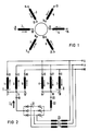
- FIG 1 die räumliche Lage der Teilwicklungen einer Drehstrommaschine,
- FIG 2 die Schaltung dieser Teilwicklungen mit einer Anordnung zur Gewinnung des veränderbaren Gleichstromes,
- FIG 3 die räumliche Lage der Teilwicklungen einer Einphasenmaschine und
- FIG 4 die Schaltung dieser Teilwicklungen mit einer Schaltung zur Gewinnung des veränderbaren Gleichstromes.
- In FIG 1 ist die Anordnung von sechs Teilwicklungen 1 bis 6 bezogen auf zwei benachbarte Polteilungen einer asynchronen Drehstrommaschine dargestellt. Jede dieser Teilwicklungen 1 bis 6 erstreckt sich bei zweipoligen Maschinen nur über eine Polteilung, bei höherpoligen Maschinen nur über von gleichpoligen induzierenden Magnetfeldern durchsetzte Teile des Ankerumfanges. Die hintereinander- oder parallelgeschalteten Teile der einzelnen Teilwicklungen 1 bis 6 sind dann schrittweise um zwei Polteilungen gegeneinander versetzt. Die Teilwicklungen 1 bis 6 sind aufeinanderfolgend um jeweils ein Drittel einer Polteilung versetzt angeordnet und bilden, wie durch Vergleich der Klemmenbezeichnungen 7 bis 18 in den Figuren 1 und 2 hervorgeht, zwei an den Ausgangsklemmen U, V, W parallelgeschaltete dreiphasige Wicklungsgruppen I und II mit den getrennten Sternpunkten 19 und 20.
- Aus FIG 1 ist ferner ersichtlich, daß die gleichphasigen Teilwicklungen 1, 4 bzw. 3, 6 bzw. 5, 2 jeweils um eine Polteilung gegeneinander versetzt sind. Die beiden Sternpunkte 19 und 20 sind hinsichtlich der induzierten Wechselspannungen äquipotential. Bezüglich des in die Sternpunkte 19 und 20 eingespeisten veränderbaren Gleichstromes IG sind die Ausgangsklemmen U, V, W der Ankerwicklung äquipotential, somit beeinflußt dieser Gleichstrom den äußeren Stromkreis der Maschine nicht. Der Gleichstrom IG kann grundsätzlich von einer beliebigen, zu den Teilwicklungen 1 bis 6 potentialfremden Gleichstromquelle bezogen werden. Im Beispiel nach FIG 2 liefert ein halbgesteuerter Brückengleichrichter 21 über eine Glättungsdrossel 22 den erforderlichen Gleichstrom IG. Der Brückengleichrichter 21 wird von der Sekundärwicklung eines Transformators 23 gespeist, der primärseitig an die Ankerwicklung angeschlossen ist. Der Transformator 23 bewirkt einerseits eine Potentialtrennung des Brückengleichrichters 21 von der Ankerwicklung der Maschine, andererseits formt er die Speisespannung des Brückengleichrichters 21 auf den für den erforderlichen Gleichspannungsbereich optimalen Wert um.
- Der Gleichstrom IG erzeugt in den einzelnen Teilwicklungen 1 bis 6 die in den Figuren 1 und 2 durch Pfeile angedeuteten Durchflutungen. Sie sind alle radial und gleichsinnig gerichtet, erzeugen also ein homopolares Magnetfeld.
- Die FIG 3 zeigt die Lage von vier Teilwicklungen 24 bis 27 bezogen auf zwei benachbarte Polteilungen einer permanentmagneterregten einphasigen Synchronmaschine. Auch hier erstreckt sich jede dieser Teilwicklungen 24 bis 27 bei zweipoligen Maschinen nur über eine Polteilung, bei höherpoligen Maschinen nur über von gleichpoligen induzierenden Magnetfeldern durchsetzte Teile des Ankerumfanges. Die Teilwicklungen 24 bis 27 bilden den die Nutzleistung abgegebenen Teil der Ankerwicklung. Zur Gewinnung des Gleichstromes IG ist eine getrennte Zusatzwicklung 36 geringer Leistung vorgesehen. Da sich bei Einphasenmaschinen die Arbeitswicklung (Teilwicklungen 24 bis 27) nicht über alle Ankernuten erstreckt, ist die Zusatzwicklung 36 ohne zusätzlichen Raumbedarf unterbringbar.
- FIG 4 stellt die Schaltung der nach FIG 3 angeordneten Teilwicklungen 24 bis 27 und der Zusatzwicklung 36 mit einer Anordnung zur Gewinnung des veränderbaren Gleichstromes IG dar. Die Teilwicklungen 24 und 25 sind lt. FIG 3 um eine Polteilung gegeneinander versetzt und gemäß FIG 4 zu einer Wicklungsgruppe III hintereinandergeschaltet und an die Ausgangsklemmen U1 und U2 angeschlossen. Desgleichen sind die Teilwicklungen 26 und 27 zu einer Wicklungsgruppe IV hintereinandergeschaltet und ebenfalls an die Ausgangsklemmen U1 und U2 angeschlossen. Auch die jeweils an der gleichen Ausgangsklemme angeschlossenen Teilwicklungen 25 und 26 bzw. 24 und 27 sind um eine Polteilung gegeneinander versetzt. Der Gleichstrom IG, der in die hinsichtlich der induzierten Wechselspannungen äquipotentialen Punkte 39 und 40 eingespeist wird, erzeugt in den Teilwicklungen 24 bis 27 die in den Figuren 3 und 4 durch Pfeile angedeuteten Durchflutungen, die, wie aus FIG 3 hervorgeht, radial und gleichsinnig gerichtet sind und somit ein homopolares Magnetfeld hervorrufen. Der ver änderbare Gleichstrom IG wird über eine Glättungsdrossel 22 von einem halbgesteuerten Brückengleichrichter 41 geliefert, den die Zusatzwicklung 36 speist.
- Ist eine Maschine nach den Figuren 3 und 4 zweipolig oder mit einer anderen ungeraden Polpaarzahl ausgebildet, so müssen die Teilwicklungen 24 und 26 sowie die Teilwicklungen 25 und 27 jeweils an den gleichen Stellen des Ankerumfanges angeordnet sein. Wenn zur Vermeidung von örtlichen Schwankungen des homopolaren Magnetfeldes jede der Teilwicklungen 24 bis 27 als ungesehnte Zweischichtwicklung ausgebildet ist, so ergibt dies insgesamt vier Wicklungsschichten in jeder bewickelten Nut. Das wird vermieden, wenn die gegenseitige Versetzung der Teilwicklungen 24 und 25 sowie der Teilwicklungen 26 und 27 nicht um eine ganze Polteilung erfolgt, sondern hiervon zumindest um eine Nutteilung abweicht. Dies ermöglicht eine Verschachtelung der Teilwicklungen 24 und 26 sowie der Teilwicklungen 25 und 27 und damit eine Ausführung mit nur zwei Wicklungsschichten je bewickelter Nut. Die Wechselspannungen in den hintereinandergeschalteten Teilwicklungen 24, 25 bzw. 26, 27 jeder Wicklungsgrppe III bzw. IV sind dann nicht mehr genau gleichphasig, was jedoch die Wirkungsweise des Gleichstromes IG nicht beeinflußt.
- Bei einer Maschine nach den Figuren 3 und 4 mit gerader Polpaarzahl brauchen die Teilwicklungen 24 und 26 bzw. 25 und 27 nicht an den gleichen Stellen des Ankerumfanges zu liegen, sie können vielmehr auch um zwei Polteilungen gegeneinander versetzt angeordnet werden. Bei beibehaltener Gleichphasigkeit der Teilwicklungen jeder Wicklungsgruppe III bzw. IV ergeben sich dann nur zwei Wicklungsschichten in jeder bewickelten Nut.
Claims (5)
Applications Claiming Priority (2)
| Application Number | Priority Date | Filing Date | Title |
|---|---|---|---|
| DE3817594 | 1988-05-24 | ||
| DE3817594 | 1988-05-24 |
Publications (3)
| Publication Number | Publication Date |
|---|---|
| EP0343456A2 true EP0343456A2 (de) | 1989-11-29 |
| EP0343456A3 EP0343456A3 (en) | 1990-05-30 |
| EP0343456B1 EP0343456B1 (de) | 1993-08-04 |
Family
ID=6355000
Family Applications (1)
| Application Number | Title | Priority Date | Filing Date |
|---|---|---|---|
| EP89108605A Expired - Lifetime EP0343456B1 (de) | 1988-05-24 | 1989-05-12 | Elektrische Maschine, bei der aktive Eisenteile durch ein homopolares Magnetfeld vormagnetisierbar sind |
Country Status (2)
| Country | Link |
|---|---|
| EP (1) | EP0343456B1 (de) |
| DE (1) | DE58905103D1 (de) |
Family Cites Families (1)
| Publication number | Priority date | Publication date | Assignee | Title |
|---|---|---|---|---|
| DE1095387B (de) * | 1955-07-15 | 1960-12-22 | Licentia Gmbh | Asynchronmotor mit einem durch Vormagnetisierung mittels zusaetzlicher Vormagnetisierungswicklung veraenderlich einstellbaren bzw. regelbaren Betriebsverhalten |
-
1989
- 1989-05-12 DE DE8989108605T patent/DE58905103D1/de not_active Expired - Fee Related
- 1989-05-12 EP EP89108605A patent/EP0343456B1/de not_active Expired - Lifetime
Also Published As
| Publication number | Publication date |
|---|---|
| DE58905103D1 (de) | 1993-09-09 |
| EP0343456A3 (en) | 1990-05-30 |
| EP0343456B1 (de) | 1993-08-04 |
Similar Documents
| Publication | Publication Date | Title |
|---|---|---|
| DE2600035C3 (de) | Elektrischer Stromrichtergenerator mit wenigstens einer Feldwicklung und wenigstens einer Ankerwicklung | |
| DE1613092B2 (de) | Zweischicht-Schleifenwicklung fur einen mehrphasigen dynamoelektrischen Generator | |
| DE2743699C2 (de) | ||
| DE2744472B1 (de) | Elektrischer Zweimotorenantrieb | |
| DE60024221T2 (de) | Elektrische Maschine mit Ankerwicklung | |
| DE1813370B2 (de) | Kompoundiertes Erregersystem | |
| DE69803353T2 (de) | Dreiphasiger, bürstenloser, Synchrongenerator mit verstärktem Läuferfeldsystem | |
| DE2914185A1 (de) | Generator mit permanentmagnet | |
| EP0343456B1 (de) | Elektrische Maschine, bei der aktive Eisenteile durch ein homopolares Magnetfeld vormagnetisierbar sind | |
| DE3014352A1 (de) | Schaltungsanordnung fuer ein- oder mehrphasige elektrische maschinen | |
| DE571048C (de) | Synchroner Einankerumformer zur Umformung von Ein- oder Mehrphasenstrom einer Frequenz in solchen anderer Frequenz | |
| DE2221893A1 (de) | Erregeranordnung | |
| DE1290242B (de) | Elektrische Maschine mit veraenderlichem magnetischem Widerstand | |
| DE102004036727A1 (de) | Elektrische Maschine mit mehreren Wicklungssystemen | |
| DE647376C (de) | Polumschaltbare Dreiphasenwicklung | |
| DE2943242C2 (de) | Schleifringloser Stromrichter-Synchronmotor | |
| DE2532338C2 (de) | Kurzschlußläuferwicklung für einen umrichtergespeisten Asynchronmotor | |
| DE3427103A1 (de) | Elektrische maschine veraenderlicher drehzahl mit permanentmagnetischer laeufererregung | |
| AT226316B (de) | Wicklungsanordnung für Synchronmaschinen | |
| DE2508374A1 (de) | Einphasen-induktionsmotor | |
| DE455158C (de) | Dynamoelektrische Maschine des Einzelmaschinen-Kaskadentyps | |
| DE2518786B2 (de) | Sechsphasen-Ständerwicklung einer elektrischen Maschine | |
| DE1042093B (de) | Wechselpol-Reluktanzmaschine | |
| DE2459714A1 (de) | Buerstenloser wechselstrom-synchronmotor | |
| AT206999B (de) | Anordnung zum Betrieb, insbesondere zum Anfahren eines Einphasenkollektormotors |
Legal Events
| Date | Code | Title | Description |
|---|---|---|---|
| PUAI | Public reference made under article 153(3) epc to a published international application that has entered the european phase |
Free format text: ORIGINAL CODE: 0009012 |
|
| AK | Designated contracting states |
Kind code of ref document: A2 Designated state(s): DE FR GB SE |
|
| PUAL | Search report despatched |
Free format text: ORIGINAL CODE: 0009013 |
|
| AK | Designated contracting states |
Kind code of ref document: A3 Designated state(s): DE FR GB SE |
|
| 17P | Request for examination filed |
Effective date: 19901009 |
|
| 17Q | First examination report despatched |
Effective date: 19920810 |
|
| GRAA | (expected) grant |
Free format text: ORIGINAL CODE: 0009210 |
|
| AK | Designated contracting states |
Kind code of ref document: B1 Designated state(s): DE FR GB SE |
|
| REF | Corresponds to: |
Ref document number: 58905103 Country of ref document: DE Date of ref document: 19930909 |
|
| ET | Fr: translation filed | ||
| GBT | Gb: translation of ep patent filed (gb section 77(6)(a)/1977) |
Effective date: 19931027 |
|
| PGFP | Annual fee paid to national office [announced via postgrant information from national office to epo] |
Ref country code: GB Payment date: 19940418 Year of fee payment: 6 |
|
| PGFP | Annual fee paid to national office [announced via postgrant information from national office to epo] |
Ref country code: FR Payment date: 19940519 Year of fee payment: 6 |
|
| PGFP | Annual fee paid to national office [announced via postgrant information from national office to epo] |
Ref country code: SE Payment date: 19940526 Year of fee payment: 6 |
|
| PLBE | No opposition filed within time limit |
Free format text: ORIGINAL CODE: 0009261 |
|
| STAA | Information on the status of an ep patent application or granted ep patent |
Free format text: STATUS: NO OPPOSITION FILED WITHIN TIME LIMIT |
|
| 26N | No opposition filed | ||
| EAL | Se: european patent in force in sweden |
Ref document number: 89108605.0 |
|
| PG25 | Lapsed in a contracting state [announced via postgrant information from national office to epo] |
Ref country code: DE Effective date: 19950201 |
|
| PG25 | Lapsed in a contracting state [announced via postgrant information from national office to epo] |
Ref country code: GB Effective date: 19950512 |
|
| PG25 | Lapsed in a contracting state [announced via postgrant information from national office to epo] |
Ref country code: SE Effective date: 19950513 |
|
| GBPC | Gb: european patent ceased through non-payment of renewal fee |
Effective date: 19950512 |
|
| EUG | Se: european patent has lapsed |
Ref document number: 89108605.0 |
|
| PG25 | Lapsed in a contracting state [announced via postgrant information from national office to epo] |
Ref country code: FR Effective date: 19960229 |
|
| REG | Reference to a national code |
Ref country code: FR Ref legal event code: ST |
|
| REG | Reference to a national code |
Ref country code: FR Ref legal event code: ST |