EP0343041A1 - Von einem elektrischen Motor angetriebene Leiter - Google Patents
Von einem elektrischen Motor angetriebene Leiter Download PDFInfo
- Publication number
- EP0343041A1 EP0343041A1 EP89401305A EP89401305A EP0343041A1 EP 0343041 A1 EP0343041 A1 EP 0343041A1 EP 89401305 A EP89401305 A EP 89401305A EP 89401305 A EP89401305 A EP 89401305A EP 0343041 A1 EP0343041 A1 EP 0343041A1
- Authority
- EP
- European Patent Office
- Prior art keywords
- ladder
- assembly according
- fixed
- reverse
- assembly
- Prior art date
- Legal status (The legal status is an assumption and is not a legal conclusion. Google has not performed a legal analysis and makes no representation as to the accuracy of the status listed.)
- Granted
Links
- XEEYBQQBJWHFJM-UHFFFAOYSA-N Iron Chemical compound [Fe] XEEYBQQBJWHFJM-UHFFFAOYSA-N 0.000 claims description 4
- VJYFKVYYMZPMAB-UHFFFAOYSA-N ethoprophos Chemical compound CCCSP(=O)(OCC)SCCC VJYFKVYYMZPMAB-UHFFFAOYSA-N 0.000 claims description 3
- 238000009423 ventilation Methods 0.000 claims description 3
- 239000011810 insulating material Substances 0.000 claims description 2
- 229910052742 iron Inorganic materials 0.000 claims description 2
- 238000013021 overheating Methods 0.000 claims description 2
- 230000001681 protective effect Effects 0.000 claims description 2
- 239000003638 chemical reducing agent Substances 0.000 description 3
- 239000002184 metal Substances 0.000 description 3
- 229910052751 metal Inorganic materials 0.000 description 3
- 230000009466 transformation Effects 0.000 description 2
- 206010014357 Electric shock Diseases 0.000 description 1
- 229910000831 Steel Inorganic materials 0.000 description 1
- 241001080024 Telles Species 0.000 description 1
- 239000000969 carrier Substances 0.000 description 1
- 238000009434 installation Methods 0.000 description 1
- 238000005096 rolling process Methods 0.000 description 1
- 239000010959 steel Substances 0.000 description 1
Images


Classifications
-
- E—FIXED CONSTRUCTIONS
- E06—DOORS, WINDOWS, SHUTTERS, OR ROLLER BLINDS IN GENERAL; LADDERS
- E06C—LADDERS
- E06C1/00—Ladders in general
- E06C1/02—Ladders in general with rigid longitudinal member or members
- E06C1/38—Special constructions of ladders, e.g. ladders with more or less than two longitudinal members, ladders with movable rungs or other treads, longitudinally-foldable ladders
- E06C1/397—Special constructions of ladders, e.g. ladders with more or less than two longitudinal members, ladders with movable rungs or other treads, longitudinally-foldable ladders characterised by having wheels, rollers, or runners
-
- E—FIXED CONSTRUCTIONS
- E06—DOORS, WINDOWS, SHUTTERS, OR ROLLER BLINDS IN GENERAL; LADDERS
- E06C—LADDERS
- E06C9/00—Ladders characterised by being permanently attached to fixed structures, e.g. fire escapes
- E06C9/06—Ladders characterised by being permanently attached to fixed structures, e.g. fire escapes movably mounted
- E06C9/08—Ladders characterised by being permanently attached to fixed structures, e.g. fire escapes movably mounted with rigid longitudinal members
- E06C9/12—Ladders characterised by being permanently attached to fixed structures, e.g. fire escapes movably mounted with rigid longitudinal members laterally displaceable
Definitions
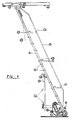
- the present invention relates to a ladder of the industrial type comprising two wheels allowing it to be moved and a trolley provided with four rollers sliding on an I P N.
- the object of the present invention is to avoid these drawbacks by producing a motorized ladder of a new type which eliminates any fatigue on the part of the user: he can at his will perform his work at the desired height no longer needing to go down, these movement operations are done with the right hand which activates the push buttons to start at the exact place where it is: forward, reverse.
- the non-negligible advantage of this invention consists in starting and stopping without any sudden, securing the user for the risk of falls, this achievement is due to the installation of an electronic frequency converter from 0 to 120 hertz him even controlled by a microprocessor which regulates the rise and fall times of the motor supply.
- Another advantage for the user it has a safety ramp specially designed to enlarge its working place allowing it to move without narrowness when it is occupied, and high enough so that it can lean taking thus a good working position.
- a safety device When the ladder moves forward with its user, a safety device is fixed by two movable yokes, called a hanging bar provided with a limit switch which automatically cuts the power to the motor, this in case a third party is busy working in the passage of the ladder.
- the wiring along the handrail is 10 volts, eliminating the risk of electric shock.
- the subject of the invention is a motor assembly of a ladder provided in the upper part of a carriage moving along a rail and in the lower part of two wheels integral with each of the two uprights, characterized in what it consists of a motor assembly comprising pulley (10) belt (4), gearmotor (6) (7) mounted on a support frame (5) allowing its attachment to the uprights (1) of the scale by bolts housed under said ladder and supplied by a power cable (20) and by a conductive sheath (21) connected to the rail (19) by supports (29) and in which are received friction rollers arranged at the top of the cable d 'power supply, the control being provided by contactors (12) forward, reverse.
- a motor assembly comprising pulley (10) belt (4), gearmotor (6) (7) mounted on a support frame (5) allowing its attachment to the uprights (1) of the scale by bolts housed under said ladder and supplied by a power cable (20) and by a conductive sheath (21) connected to the rail (19) by supports (29) and in which are
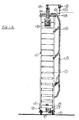
- an electronic variator (15) is provided placed in a metal box at the top of the scale and fixed by flat iron flanges incorporating a microprocessor controlling the ascents and descents of the speed of rotation of the gearmotor group (6) (7) in forward and reverse.
- Safety means are further provided in the form of a square tube frame (14) provided with two horizontal protection plates (30) articulated on two movable yokes (13) fixed by screws under the uprights (1) of the ladder for actuating a limit switch (18) which cuts the supply as soon as there is an obstacle. It includes a protection formed by a ramp (11) forming a railing through which passes the power cable (20) held by arms (13) of superimposed connection support.
- An engine ventilation casing (8) is provided in expanded metal fixed by screws on the casing (5).
- the pushers (12) are arranged on three levels at the connecting arms (13) of the ramp (11) grouped by two with indication carriers in insulating material and indicating forward and reverse.
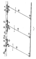
- each of the scales is then adjusted to cover a rolling distance, for example 10 meters.
- This safety means has been provided in front of the ladder in the form of a square articulated tu be coming to meet as soon as there is an obstacle a limit switch which cuts the power supply and at the end of the rail (19) is provided a fixed antenna (33) actuating the contactor (34) of the first scale, similarly at the end of the rail a fixed antenna (33) is provided intended to actuate a second contact (34) provided on the last ladder opposite.
- the invention also provides a rear safety device in the form of a flexible cover (36) illustrated in FIG. (8) fixed on the protective cover (5) of the existing engine assembly coming to meet as soon as there is obstacle a limit switch (37) thus securing the reverse of the ladder.
- a time switch is attached near the electrical connection box; this being set for the daily working time is cut in the evening and is reset in the morning.
Landscapes
- Engineering & Computer Science (AREA)
- Mechanical Engineering (AREA)
- Ladders (AREA)
Applications Claiming Priority (2)
| Application Number | Priority Date | Filing Date | Title |
|---|---|---|---|
| FR8806343A FR2631376B1 (fr) | 1988-05-11 | 1988-05-11 | Ensemble de motorisation pour echelle supportee par rail superieur et roues inferieures |
| FR8806343 | 1988-05-11 |
Publications (2)
| Publication Number | Publication Date |
|---|---|
| EP0343041A1 true EP0343041A1 (de) | 1989-11-23 |
| EP0343041B1 EP0343041B1 (de) | 1991-04-03 |
Family
ID=9366214
Family Applications (1)
| Application Number | Title | Priority Date | Filing Date |
|---|---|---|---|
| EP19890401305 Expired - Lifetime EP0343041B1 (de) | 1988-05-11 | 1989-05-10 | Von einem elektrischen Motor angetriebene Leiter |
Country Status (3)
| Country | Link |
|---|---|
| EP (1) | EP0343041B1 (de) |
| DE (1) | DE68900055D1 (de) |
| FR (1) | FR2631376B1 (de) |
Cited By (1)
| Publication number | Priority date | Publication date | Assignee | Title |
|---|---|---|---|---|
| EP0378801A1 (de) * | 1989-01-18 | 1990-07-25 | Schreyer Constructions Metalliques S.A. | Rolleiter |
Citations (3)
| Publication number | Priority date | Publication date | Assignee | Title |
|---|---|---|---|---|
| US3232375A (en) * | 1964-03-13 | 1966-02-01 | William Hugh Brown | Self-propelled scaffold |
| US3340960A (en) * | 1965-12-13 | 1967-09-12 | Louis F Wilson | Ladder |
| US3735838A (en) * | 1972-05-22 | 1973-05-29 | Everett Sound Machine Works In | Wheeled ladder with a weight actuated self-locking wheel thereon |
-
1988
- 1988-05-11 FR FR8806343A patent/FR2631376B1/fr not_active Expired - Lifetime
-
1989
- 1989-05-10 DE DE8989401305T patent/DE68900055D1/de not_active Expired - Lifetime
- 1989-05-10 EP EP19890401305 patent/EP0343041B1/de not_active Expired - Lifetime
Patent Citations (3)
| Publication number | Priority date | Publication date | Assignee | Title |
|---|---|---|---|---|
| US3232375A (en) * | 1964-03-13 | 1966-02-01 | William Hugh Brown | Self-propelled scaffold |
| US3340960A (en) * | 1965-12-13 | 1967-09-12 | Louis F Wilson | Ladder |
| US3735838A (en) * | 1972-05-22 | 1973-05-29 | Everett Sound Machine Works In | Wheeled ladder with a weight actuated self-locking wheel thereon |
Cited By (1)
| Publication number | Priority date | Publication date | Assignee | Title |
|---|---|---|---|---|
| EP0378801A1 (de) * | 1989-01-18 | 1990-07-25 | Schreyer Constructions Metalliques S.A. | Rolleiter |
Also Published As
| Publication number | Publication date |
|---|---|
| DE68900055D1 (de) | 1991-05-08 |
| EP0343041B1 (de) | 1991-04-03 |
| FR2631376B1 (fr) | 1990-08-17 |
| FR2631376A1 (fr) | 1989-11-17 |
Similar Documents
| Publication | Publication Date | Title |
|---|---|---|
| EP1170167A1 (de) | Flugzeugsitz mit verstellbaren Bein- und Fussstütze | |
| EP3908547B1 (de) | Hubarbeitsbühne mit abnehmbarer steuerkonsole, mit einer schutzvorrichtung zur verhinderung von quetschungen der bedienperson | |
| FR2836468A1 (fr) | Nacelle elevatrice a securite amelioree | |
| WO1990000997A1 (fr) | Appareil pour la manutention de charges lourdes, tel qu'un diable ou fauteuil roulant pour handicapes | |
| GB2242126A (en) | A bath | |
| EP2206425A1 (de) | Vorrichtung, die eine Heckenschere bildet und ein Zubehörteil für eine motorisierte Maschine, wie z.B. einen Aufsitzmäher, darstellt | |
| EP0905083B1 (de) | Wagen mit Hubmast, geeignet zur Montage an das Ende eines Transportfahrzeugs | |
| EP0399878B1 (de) | Mischer mit beweglichem Schutzschirm | |
| EP0343041B1 (de) | Von einem elektrischen Motor angetriebene Leiter | |
| FR2923378A1 (fr) | Dispositif pour deposer automatiquement une urne funeraire dans un caveau ou un columbarium | |
| BE1010411A7 (fr) | Chariot porte tailles haies multiples a fonctionnement automtique. | |
| FR2611549A3 (fr) | Cisaille motorisee auto-alimentee | |
| FR2587663A1 (fr) | Dispositif antivol pour vehicule automobile agissant au niveau du siege du conducteur et son procede de mise en oeuvre | |
| FR2689073A1 (fr) | Appareillage de manutention de charges allongées sur le toit d'un véhicule. | |
| EP0880348A1 (de) | Motorischer aufrichtstuhl | |
| EP0113603B1 (de) | Elektrischer Kraftfahrzeugfensterheber | |
| CH690084A5 (fr) | Dispositif automatique d'ébranchage et/ou d'écorçage d'arbres sur pied. | |
| EP4211070B1 (de) | Hebemaschine, wie z.b. freileitungslift, zum heben von personen und gegebenenfalls lasten | |
| WO1993024197A1 (fr) | Haie d'equitation a barre a hauteur reglable de façon continue | |
| EP0002092B1 (de) | Gemüseschneidemaschine | |
| EP0728431A1 (de) | Lehnstuhl | |
| FR2591875A1 (fr) | Dispositif a module standard pour le reglage en hauteur de l'assise d'un siege | |
| EP0117862A2 (de) | Hebevorrichtung, insbesondere Arbeitsplattform | |
| FR2663581A1 (fr) | Mat porte outil pour outils tels que taille-haies, pulverisateurs ou autres outillages. | |
| FR2712820A1 (fr) | Système de réglage à distance de la hauteur d'obstacles hippiques. |
Legal Events
| Date | Code | Title | Description |
|---|---|---|---|
| PUAI | Public reference made under article 153(3) epc to a published international application that has entered the european phase |
Free format text: ORIGINAL CODE: 0009012 |
|
| AK | Designated contracting states |
Kind code of ref document: A1 Designated state(s): BE CH DE ES FR GB IT LI NL SE |
|
| 17P | Request for examination filed |
Effective date: 19900122 |
|
| 17Q | First examination report despatched |
Effective date: 19900627 |
|
| ITF | It: translation for a ep patent filed | ||
| GRAA | (expected) grant |
Free format text: ORIGINAL CODE: 0009210 |
|
| AK | Designated contracting states |
Kind code of ref document: B1 Designated state(s): BE CH DE ES FR GB IT LI NL SE |
|
| PG25 | Lapsed in a contracting state [announced via postgrant information from national office to epo] |
Ref country code: SE Effective date: 19910403 Ref country code: NL Effective date: 19910403 Ref country code: ES Free format text: THE PATENT HAS BEEN ANNULLED BY A DECISION OF A NATIONAL AUTHORITY Effective date: 19910403 |
|
| REF | Corresponds to: |
Ref document number: 68900055 Country of ref document: DE Date of ref document: 19910508 |
|
| PG25 | Lapsed in a contracting state [announced via postgrant information from national office to epo] |
Ref country code: LI Effective date: 19910531 Ref country code: CH Effective date: 19910531 Ref country code: BE Effective date: 19910531 |
|
| GBT | Gb: translation of ep patent filed (gb section 77(6)(a)/1977) | ||
| NLV1 | Nl: lapsed or annulled due to failure to fulfill the requirements of art. 29p and 29m of the patents act | ||
| BERE | Be: lapsed |
Owner name: PERIN SERGE Effective date: 19910531 |
|
| REG | Reference to a national code |
Ref country code: CH Ref legal event code: PL |
|
| PLBE | No opposition filed within time limit |
Free format text: ORIGINAL CODE: 0009261 |
|
| STAA | Information on the status of an ep patent application or granted ep patent |
Free format text: STATUS: NO OPPOSITION FILED WITHIN TIME LIMIT |
|
| PGFP | Annual fee paid to national office [announced via postgrant information from national office to epo] |
Ref country code: DE Payment date: 19920219 Year of fee payment: 3 |
|
| 26N | No opposition filed | ||
| PG25 | Lapsed in a contracting state [announced via postgrant information from national office to epo] |
Ref country code: DE Effective date: 19930202 |
|
| PGFP | Annual fee paid to national office [announced via postgrant information from national office to epo] |
Ref country code: GB Payment date: 19950510 Year of fee payment: 7 |
|
| PG25 | Lapsed in a contracting state [announced via postgrant information from national office to epo] |
Ref country code: GB Effective date: 19960510 |
|
| GBPC | Gb: european patent ceased through non-payment of renewal fee |
Effective date: 19960510 |
|
| REG | Reference to a national code |
Ref country code: FR Ref legal event code: ST |
|
| REG | Reference to a national code |
Ref country code: FR Ref legal event code: RN Ref country code: FR Ref legal event code: FC |
|
| PG25 | Lapsed in a contracting state [announced via postgrant information from national office to epo] |
Ref country code: IT Free format text: LAPSE BECAUSE OF NON-PAYMENT OF DUE FEES;WARNING: LAPSES OF ITALIAN PATENTS WITH EFFECTIVE DATE BEFORE 2007 MAY HAVE OCCURRED AT ANY TIME BEFORE 2007. THE CORRECT EFFECTIVE DATE MAY BE DIFFERENT FROM THE ONE RECORDED. Effective date: 20050510 |
|
| PGFP | Annual fee paid to national office [announced via postgrant information from national office to epo] |
Ref country code: FR Payment date: 20051108 Year of fee payment: 17 |
|
| REG | Reference to a national code |
Ref country code: FR Ref legal event code: TP Ref country code: FR Ref legal event code: GC |
|
| REG | Reference to a national code |
Ref country code: FR Ref legal event code: ST Effective date: 20070131 |
|
| PG25 | Lapsed in a contracting state [announced via postgrant information from national office to epo] |
Ref country code: FR Free format text: LAPSE BECAUSE OF NON-PAYMENT OF DUE FEES Effective date: 20060531 |