EP4211070B1 - Hebemaschine, wie z.b. freileitungslift, zum heben von personen und gegebenenfalls lasten - Google Patents
Hebemaschine, wie z.b. freileitungslift, zum heben von personen und gegebenenfalls lasten Download PDFInfo
- Publication number
- EP4211070B1 EP4211070B1 EP21778184.8A EP21778184A EP4211070B1 EP 4211070 B1 EP4211070 B1 EP 4211070B1 EP 21778184 A EP21778184 A EP 21778184A EP 4211070 B1 EP4211070 B1 EP 4211070B1
- Authority
- EP
- European Patent Office
- Prior art keywords
- control console
- top rail
- lifting machine
- rail
- housing
- Prior art date
- Legal status (The legal status is an assumption and is not a legal conclusion. Google has not performed a legal analysis and makes no representation as to the accuracy of the status listed.)
- Active
Links
Images


Classifications
-
- G—PHYSICS
- G05—CONTROLLING; REGULATING
- G05G—CONTROL DEVICES OR SYSTEMS INSOFAR AS CHARACTERISED BY MECHANICAL FEATURES ONLY
- G05G9/00—Manually-actuated control mechanisms provided with one single controlling member co-operating with two or more controlled members, e.g. selectively, simultaneously
- G05G9/02—Manually-actuated control mechanisms provided with one single controlling member co-operating with two or more controlled members, e.g. selectively, simultaneously the controlling member being movable in different independent ways, movement in each individual way actuating one controlled member only
- G05G9/04—Manually-actuated control mechanisms provided with one single controlling member co-operating with two or more controlled members, e.g. selectively, simultaneously the controlling member being movable in different independent ways, movement in each individual way actuating one controlled member only in which movement in two or more ways can occur simultaneously
- G05G9/047—Manually-actuated control mechanisms provided with one single controlling member co-operating with two or more controlled members, e.g. selectively, simultaneously the controlling member being movable in different independent ways, movement in each individual way actuating one controlled member only in which movement in two or more ways can occur simultaneously the controlling member being movable by hand about orthogonal axes, e.g. joysticks
- G05G9/04785—Manually-actuated control mechanisms provided with one single controlling member co-operating with two or more controlled members, e.g. selectively, simultaneously the controlling member being movable in different independent ways, movement in each individual way actuating one controlled member only in which movement in two or more ways can occur simultaneously the controlling member being movable by hand about orthogonal axes, e.g. joysticks the controlling member being the operating part of a switch arrangement
- G05G9/04788—Manually-actuated control mechanisms provided with one single controlling member co-operating with two or more controlled members, e.g. selectively, simultaneously the controlling member being movable in different independent ways, movement in each individual way actuating one controlled member only in which movement in two or more ways can occur simultaneously the controlling member being movable by hand about orthogonal axes, e.g. joysticks the controlling member being the operating part of a switch arrangement comprising additional control elements
-
- B—PERFORMING OPERATIONS; TRANSPORTING
- B66—HOISTING; LIFTING; HAULING
- B66F—HOISTING, LIFTING, HAULING OR PUSHING, NOT OTHERWISE PROVIDED FOR, e.g. DEVICES WHICH APPLY A LIFTING OR PUSHING FORCE DIRECTLY TO THE SURFACE OF A LOAD
- B66F11/00—Lifting devices specially adapted for particular uses not otherwise provided for
- B66F11/04—Lifting devices specially adapted for particular uses not otherwise provided for for movable platforms or cabins, e.g. on vehicles, permitting workmen to place themselves in any desired position for carrying out required operations
- B66F11/042—Lifting devices specially adapted for particular uses not otherwise provided for for movable platforms or cabins, e.g. on vehicles, permitting workmen to place themselves in any desired position for carrying out required operations actuated by lazy-tongs mechanisms or articulated levers
Definitions
- the present invention relates to a lifting machine, such as a lifting platform, for lifting people and possibly loads and a method of coupling to the upper rail of a guardrail of such a machine a control console for the lifting mechanism of said machine.
- a lifting machine comprising a work platform, a lifting mechanism for said work platform, and a control console for controlling at least the lifting mechanism
- said work platform comprising a floor and a guardrail forming the longitudinal and transverse walls of an enclosure surrounding at least part of said floor
- said guardrail comprising at least one upper rail called a handrail called a non-circular section, this upper rail having a top face and a bottom face
- the control console comprising a fixing device to allow a removable coupling of the control console to the upper rail
- the control console comprising a fixing device to allow a removable coupling of the control console at least to the upper rail.
- Lifting machines in particular lifting platforms, require a control panel for their operation, in particular for controlling the lifting mechanism and, possibly, for controlling the advance of the machine.
- a space on the lifting machine has been dedicated to receiving said control panel, including when the control panel is removably mounted on the work platform.
- the removable coupling solutions such as those described, for example, in the patent FR 3 050 193 (which discloses the preamble of claim 1) or FR 3 091 524 are not reliable.
- An aim of the invention is to propose a lifting machine whose design makes it possible to improve the working conditions of the operator while providing safe coupling of the control panel to the guardrail of the machine.
- the invention relates to a lifting machine comprising a work platform, a lifting mechanism for said work platform, and a control console for controlling at least the lifting mechanism, said work platform comprising a floor and a guardrail forming the longitudinal and transverse walls of an enclosure surrounding at least part of said floor, said guardrail comprising at least one upper rail called a handrail of non-circular section, this upper rail having a top face and a bottom face and the control console comprising a fixing device to allow a removable coupling of the control console to the upper rail, characterized in that the control console can be coupled by snap-fastening to the upper rail, in that the fixing device of the control console comprises, for a snap-fastening coupling of the control console to the upper rail, one or more fixing members that are at least partially elastically deformable and in that the control console has at least one so-called support surface, capable of coming into support contact with the upper beam in the coupled state of the control panel to the upper beam, at least part of the support surface and at least part of the or at
- the control panel can be coupled by elastic snap-fastening, also simply called snap-fastening to the upper beam.
- the terms snap-fastening or elastic snap-fastening will therefore be used interchangeably to designate the same assembly method.
- This snap-fastening or elastic snap-fastening is synonymous with the expression elastic fitting.
- This snap-in is an assembly method, i.e. a socket in which at least one element is deformed during insertion. Thanks to the fact that the control panel is coupling by snap-fastening also called elastic snap-fastening, i.e. by elastic deformation of at least one part of the fixing device, to the upper beam, this results in the possibility of fixing the control panel simply and quickly at any location on the upper beam depending on the desired working conditions.
- Such a snap-fastening also makes it possible to easily reposition the control panel.
- the production of the upper beam with a non-circular and preferably quadrangular cross-section makes it possible, in a simple manner, to avoid rotation of the control panel around the upper beam.
- a snap-fastening coupling also makes it possible to avoid accidental uncoupling of the control panel from the upper beam.
- the so-called support surface capable of coming into support contact with the upper beam in the coupled state of the control panel to the upper beam, is a surface, preferably rigid, configured to come into support contact at least with the underside of the upper beam.
- This arrangement allows a simple, locked interlocking assembly. This assembly is particularly safe when the support surface is a rigid surface with greater rigidity than the fixing members. Thus, this support surface forms an anti-lift stop and a more complex movement is necessary to obtain uncoupling of the control panel from the upper beam.
- the or at least one of the at least partially elastically deformable fixing members of the device for fixing the control panel to the upper beam covers the upper beam from above, in the coupled state of the control panel to the upper beam. This results in simplicity of implementation.
- the or at least one of the fixing members which, in the coupled state of the control panel to the upper beam, covers the upper beam from above is a U-shaped spring clamp open towards the floor and at least a part of the or at least one of the support surfaces of the control panel is arranged opposite the web of the U to delimit with the U the housing for receiving the upper beam.
- the U comprises a web and two branches.
- the support surface is integral with one of the branches of the U.
- the housing is of generally quadrangular section and the passage for inserting the upper rail into said housing is provided in one of the corners of said housing, preferably between at least part of the support surface and one end of one of the branches of the U.
- the part of the support surface of the control console, in support contact with the underside face of the upper beam extends in a transverse plane, preferably orthogonal, to the plane passing through one of the branches of the U and at a distance from the web of the U depending on the distance between the top and bottom faces of the upper beam for a sandwiching of the top and bottom faces of the upper beam between said support surface of the control console and the web of the U.
- At least a portion of the control console in the coupled state of the control console to the upper rail, at least a portion of the control console extends at least partially in cantilever of the guardrail to generate, under the effect of the weight of said cantilever portion of the control console, a tilting torque of the control console in the direction of bringing the support surface of the control console closer to the underside of the upper rail with which the support surface of the control console is able to come into support contact.
- this arrangement makes it possible to reinforce the mechanical resistance of the snap-on assembly.
- the control console comprises at least one control member and two flanges between which the or at least one of the control members extends and at least one of the fixing members of the fixing device projects at least partially from one of the flanges towards the outside of the control console, i.e. projects from the external face of the flange, the external face corresponding to the face of the flange opposite the so-called internal face of the flange facing the other flange.
- the interior of the control panel corresponding to the space between the flanges.
- the fixing device comprising several fixing members, at least one of the fixing members of the fixing device projects at least partially from one of the flanges towards the outside of the control panel and at least the other or another of the fixing members of the fixing device projects at least partially from the other of the flanges towards the outside of the control panel,
- the control panel has distinct coupling positions to the upper beam
- the fixing members are members that can be selectively activated depending on the selected coupling position.
- the control panel has distinct coupling positions to the upper beam. The multiplication of coupling positions offers the operator the opportunity to have a comfortable position for each control action to be performed.
- the control panel is configured to move from one coupling position to another without tools. This arrangement allows rapid movement from one coupling position to another.
- One of the coupling positions of the control console may be a position in which the control console extends at least partially inside the enclosure delimited by the guardrail.
- One of the coupling positions of the control console may be a position in which the control console extends at least partially outside the enclosure delimited by the guardrail. The operator can thus have maximum space inside the enclosure when the control console extends at least partially outside the enclosure.
- the coupling positions of the control console may correspond to one, to a position in which the control console is coupled to one of the longitudinal, or respectively transverse, walls of the enclosure and the other, to a position in which the control console is coupled to the opposite longitudinal, or respectively transverse, wall of said enclosure.
- the control panel can be used by either a right-handed or a left-handed person.
- At least one of the fixing members is a multi-purpose fixing member configured to be active on the one hand, both in the positioned state of the control panel at least partially inside the enclosure and in the positioned state of the control desk at least partially outside the enclosure, on the other hand, both in the coupled state of the control desk to one of the longitudinal or respectively transverse walls of the enclosure and in the coupled state of the control desk to the other of the longitudinal or respectively transverse walls of the enclosure.
- At least one of the flanges is provided with a so-called lateral grip handle made in one piece with said flange and the control console comprises a central handle arranged between the flanges and coupled to each of the flanges.
- the invention also relates to a method of coupling, to the upper rail of a guardrail of a lifting machine, a control console used to control at least the lifting mechanism of said lifting machine, characterized in that said lifting machine being in accordance with that described above, the method comprises a step of introducing the upper rail into the insertion passage of the housing defined by at least part of the support surface and at least part of the or at least one of the fixing members during which the or at least one of the elastically deformable fixing members deforms in the direction of widening said passage and a step of continuing the introduction to a predetermined position of introduction of the upper rail into said housing in which said passage narrows.
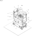
- the invention relates to a lifting machine 1 which may be in accordance with that shown in the figure 1 .
- This lifting machine 1 comprises a chassis 15, a lifting mechanism 6 mounted on the chassis 15 and a working platform 2 mounted on the lifting mechanism 6.
- the chassis 15 is provided with front wheels and rear wheels by means of which the chassis 15 rests on the ground. These wheels make it possible to move the lifting machine on the ground.
- the chassis 15 is provided with tracks for the purpose of moving on the ground.
- the lifting machine 1 may have a motorization to allow its autonomous movement on the ground. This may be an electric or combustion motorization, or even a hybrid motorization.
- the motorization is generally mounted directly on the chassis 15.
- the lifting machine 1 is not powered for the purpose of moving it on the ground. In this case, the lifting machine is towed or pushed to move it on the ground.
- the chassis 15 of the lifting device is arranged fixedly relative to the ground either on a motor vehicle, such as a truck, without the possibility of controlling the movement of the vehicle on the ground from the lifting device 1.
- the lifting machine 1 is here a scissor lifting machine.
- the lifting mechanism 6 is therefore a scissor lifting mechanism.
- This type of lifting mechanism is known per se. It comprises beams articulated at their center in the manner of scissors. These Scissor mechanisms are mounted one above the other by their ends which are pivotally connected in order to reach the desired working height.
- One or more hydraulic cylinders allow the scissor lifting mechanism 6 to be extended or retracted to raise and lower the working platform 2.
- the invention also relates to a vertical mast lifting machine 1.
- Vertical mast lifting machines 1 are known per se.
- a lifting mechanism is designed at least in the form of an extendable mast comprising vertical parts sliding on or in each other to extend vertically to the desired working height.
- Their lifting mechanism sometimes comprises a turret on which the sliding vertical parts are mounted, the turret being pivotally mounted on the chassis about a vertical axis in order to be able to vary the orientation and the working platform relative to the chassis.
- the work platform is mounted on the upper vertical part either fixedly or by means of an arm articulated to the vertical mast around a horizontal axis.
- the invention relates to any other type of lifting machine 1 regardless of the type of lifting mechanism 6 of the work platform 2.
- the work platform 2 comprises a floor 3 formed by a tray extending horizontally when the lifting machine 1 is placed on horizontal ground.
- This floor 3 can accommodate one or more people on board and possibly equipment. It is surrounded by a guardrail 4 to prevent people from falling out of the work platform 2.
- the guardrail 4 forms the longitudinal 41 and transverse 42 walls of an enclosure surrounding at least part of the floor 3.
- This guardrail here comprises four sides each corresponding to a respective side of the platform 2.
- Each wall of the guardrail 4 is hollowed out and formed by a tubular structure.
- the guardrail 4 comprises at each wall a high rail 5 called a handrail and at least one intermediate rail as well as a low rail forming a plinth.
- the rails are connected to each other by uprights. Rails and uprights form the tubular structure constituting a wall.
- At least the upper rail 5 of the guardrail 4 is a rail of non-circular cross section.
- this upper rail 5 is a rail of quadrangular cross section, the angles being able to be cut, rounded or straight.
- the upper rail 5 thus has a top face 51, a bottom face 52 and two lateral faces connecting the top faces 51 and bottom faces 52 together.
- the lifting engine 1 also includes a control panel 7 illustrated in figure 4
- the control console 7 is equipped with one or more manually operated control members 11 allowing an operator to cause the work platform 2 to move upwards to reach the desired working position and to lower it onto the chassis 15 and, where appropriate, to cause the lifting device to move on the ground.
- one of the control members 11 is a pivoting lever also called a joystick.
- This pivoting lever is movable in at least four directions (forward, backward and right, left) to control in particular the lifting mechanism 6.
- the details of these control members will not be provided because they are well known to those skilled in the art.
- Other control members, such as buttons, may also be provided.
- the control console 7 comprises two facing flanges 12 forming lateral flanges between which the control member(s) 11 extend. Indeed, the flanges 12 are connected to each other by a bridge carrying the control members 11. Each flange 12 has an internal face facing the other flange and an opposite external face. Each flange is generally made of plastic. Each flange has an upper edge and an opposite lower edge.
- each of the flanges 12 is provided with a side grip handle 13 made in one piece with said flange 12.
- This side handle 13 is formed by a through opening made in said flange 12.
- the control panel 7 also includes a central handle 14 arranged between the flanges 12 and coupled to each of the flanges 12. Again, this central handle 14 is formed by a through opening made in an attached part extending between said flanges 12.
- control panel 7 can be connected to the lifting device 1 by a wired connection as shown or by a wireless connection.
- the control console 7 further comprises a fixing device 8 to enable the control console 7 to be removably coupled to the upper beam 5.
- the control console 7 can be coupled by snap-fastening to the upper beam 5.
- the control panel 7 has distinct coupling positions to the upper beam 5 and is configured to move from one coupling position to another without tools. These coupling positions can be diverse and varied.
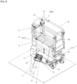
- a coupling position of the control panel 7, as illustrated in figure 2 is a position in which the control console 7 extends at least partially inside the enclosure delimited by the guardrail 4, and one of the coupling positions of the control console 7, as illustrated in figure 1 , is a position in which the control console 7 extends at least partially outside the enclosure delimited by the guardrail 4.
- Two of the coupling positions of the control console 7 correspond, one, to a position in which the control console 7 is coupled to one of the longitudinal walls 41 or, respectively, transverse walls 42 of the enclosure and, the other, to a position in which the control console 7 is coupled to the opposite longitudinal wall or, respectively, transverse wall 42 of said enclosure.
- figures 1 And 2 illustrate the case where the control console 7 is coupleable to two opposite longitudinal walls.
- the control console 7 can be used by either a right-handed or a left-handed person.
- the device 8 for fixing the control panel 7 comprises, for a snap-on coupling of the control panel 7 control to the high smooth 5, one or more fixing members 9 at least partially elastically deformable.
- the fixing device 8 comprises several fixing members 9, these fixing members 9 being selectively activatable depending on the selected coupling position.
- the fixing device 8 comprises at least two fixing members 9 which are at least partially elastically deformable, arranged, one on one of the flanges, the other on the other of the flanges 12 of the control panel 7. These fixing members 9 are here selectively active.
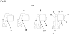
- each fixing member 9 has the shape of a U-shaped spring clamp, the inside of the U forming a space for receiving at least part of the upper beam 5.
- the fixing member 9 has the shape of a U-shaped spring clip, said U having a core 91 and two branches 92, one of the branches 92 of the U is fixed to one of the flanges 12 of the control console 7 on the so-called inner face of the flange facing the other flange.
- the U straddles the flange, in particular the so-called upper edge of the flange, so that the other branch 92 of the U extends on the outer face side opposite the inner face of the flange. Thanks to this positioning astride the U on the flange, the branches of the U extend on either side of the flange while the core of the U extends opposite the so-called upper edge of the flange.
- the control console 7 comprises two flanges 12 between which said control members 11 extend.
- Each flange 12 carries at least one fixing member 9.
- Each fixing member 9 of the fixing device 8 projects at least partially from the flange 12 which carries it in the direction of the outside of the control panel 7, that is to say projecting from the external face of the flange, the external face corresponding to the face of the flange opposite the so-called internal face of the flange facing the other flange.
- Each fixing member 9 has the shape of a U-shaped spring clip straddling said flange associated with the branches 92 of the U extending, one on the inner face of said flange, the other on the outer face of the flange and the web of the U extending opposite the so-called upper edge of said flange.
- the branch of the U extending on the inner face of the flange is fixed to said inner face of the flange to be integral with the latter during movement.
- the support surface 10 of the control panel also extends on the side of the external face of the flange.
- This support surface 10 is here produced in the form of a bead or a bulge or even a shoulder arranged on the external face side of the flange. This bead extends substantially parallel to ⁇ 20° near the upper edge of the flange.
- the U-shaped sections are therefore open towards the floor of the work platform in the fixed state of the control panel at the guardrail, in particular at the upper rail of the guardrail.
- At least a portion of the support surface 10 and at least a portion of the or at least one of the fixing members 9 define between them a housing 16 of the upper rail 5 having a passage 17 for inserting the upper rail 5 into said housing 16.
- This passage 17 is configured to, by elastic deformation of at least a portion of the or at least one of the fixing members 9, widen when the upper rail 5 is inserted into said housing before tightening beyond a predetermined position for inserting the upper rail 5 into said housing.
- at least a portion of the bearing surface 10 and at least a portion of the at least partially elastically deformable fixing member 9, in this case the branch of the U of the fixing member 9 arranged on the side of the external face of the flange define the passage for inserting the upper rail inside the U.
- the bearing surface 10 of the control console 7, in bearing contact with the surface of the underside 52 of the upper beam 5, extends in a transverse plane, preferably orthogonal, that is to say perpendicular to the plane passing through one of the branches of the U and at a distance from a plane passing through the web of the U depending on the distance between the faces of the top 51 and the bottom 52 of the upper beam 5 for a sandwiching of the faces of the top 51 and the bottom 52 of the upper beam 5 between said bearing surface 10 of the control console and the web of the U in the at least partially inserted state of the upper beam 5 inside the U.
- the housing is of generally quadrangular section and the passage for inserting the upper beam 5 into the housing is provided in one of the corners of said housing.
- the insertion passage is thus provided between at least part of the support surface 10 and one end of one of the branches of the U.
- This support surface 10 obviously extends between two planes passing, one, through one of the branches of the U, the other, through the other branch of the U formed by the fixing member 9 which has the shape of a U-shaped spring clip.
- the support surface 10 of the control console also extends on the side of the external face of the flange.
- at least a portion of the control console 7 extends at least partially in cantilever of the guardrail 4 to generate, under the effect of the weight of said cantilevered portion of the control console 7, a tilting torque of the control console 7 in the direction of bringing the support surface 10 of the control console 7 closer to the underside 52 of the upper rail 5 with which the support surface 10 of the control console 7 is in support contact.
- the non-circular shape of the upper beam makes it possible to avoid rotation of said control panel around the upper beam.
- the substantially flat top face 51 of the upper beam 5 is covered with the web of the U of the fixing member 9 in bearing contact with said top face 51.
- the substantially flat bottom face 52 of the upper beam 5 cooperates perfectly with the bearing surface 10.
- the fixing of the control panel 7 on the guardrail 4 can be carried out in a few seconds. It is sufficient, in fact, to position one of the fixing members 9 of the control console above the face of the top 51 of the upper beam 5, to lower said fixing member 9 by lowering the control console 7 to introduce the upper beam 5 into the passage formed between the bearing surface 10 and one of the branches 92 of the U, this introduction generating an elastic deformation of the U in the direction of a separation of the branches of the U, and to continue this movement until the introduction position in which the web 91 of the U is in bearing contact with the face of the top of the upper beam and the bearing surface 10 can come to position itself under the face of the bottom 52 of the upper beam 5 under the effect of the elastic force of the branches of the U in the direction of a ratment with one another.
- the method of coupling the control panel to the upper beam comprises a step of introducing the upper beam 5 into the insertion passage 17 of the housing 16 defined by at least part of the support surface 10 and at least part of the or at least one of the fixing members 9 during which the or at least one of the elastically deformable fixing members 9 deforms in the direction of widening said passage 17 and a step of continuing the introduction to a predetermined position of introduction of the upper beam 5 into said housing 16 in which said passage 17 narrows.
- Elastic deformations in the opposite direction allow easy disassembly of the control panel. It is sufficient, in fact, to act on the control panel in the direction of a separation of the branches of the U of the fixing member 9 to open the passage and allow lifting of the fixing member 9.
- the assembly and disassembly of the control panel can therefore be carried out in a short time without tools and at any location on the upper rail.
Landscapes
- Engineering & Computer Science (AREA)
- Structural Engineering (AREA)
- Life Sciences & Earth Sciences (AREA)
- Geology (AREA)
- Mechanical Engineering (AREA)
- Physics & Mathematics (AREA)
- General Physics & Mathematics (AREA)
- Automation & Control Theory (AREA)
- Vehicle Step Arrangements And Article Storage (AREA)
- Forklifts And Lifting Vehicles (AREA)
- Refuge Islands, Traffic Blockers, Or Guard Fence (AREA)
- Organic Low-Molecular-Weight Compounds And Preparation Thereof (AREA)
Claims (11)
- Hebezeug (1), umfassend eine Arbeitsplattform (2), einen Hebemechanismus (6) der Arbeitsplattform (2) und ein Bedienpult (7) zum Bedienen zumindest des Hebemechanismus (6), die Arbeitsplattform (2) umfassend einen Boden (3) und ein Geländer (4), das die Längs- (41) und Querwände (42) einer Einfassung bildet, die zumindest einen Teil des Bodens (3) umgibt, das Geländer (4) umfassend zumindest einen oberen Holm (5), der Handlauf genannt wird, mit nicht kreisförmigem Querschnitt, wobei dieser obere Holm (5) eine Oberseite (51) und eine Unterseite (52) aufweist und das Bedienpult (7) eine Befestigungsvorrichtung (8) umfasst, um eine lösbare Kopplung des Bedienpults (7) mit dem oberen Holm (5) zu ermöglichen, dadurch gekennzeichnet, dass das Bedienpult (7) durch Einrasten mit dem oberen Holm (5) koppelbar ist, dass die Vorrichtung (8) zum Befestigen des Bedienpults (7) für eine Rastverbindung des Bedienpults (7) mit dem oberen Holm (5) ein oder mehrere zumindest teilweise elastisch verformbare Befestigungselemente (9) umfasst, und dass das Bedienpult (7) zumindest eine sogenannte Auflagefläche (10) aufweist, die geeignet ist, um in dem mit dem oberen Holm (5) gekoppelten Zustand des Bedienpults (7) in Auflagekontakt mit dem oberen Holm (5) zu kommen, wobei zumindest ein Teil der Auflagefläche (10) und zumindest ein Teil des oder zumindest eines der Befestigungselemente (9) untereinander eine Aufnahme (16) des oberen Holms (5) definieren, die einen Durchgang (17) zum Einsetzen des oberen Holms (5) in diese Aufnahme aufweist, wobei dieser Durchgang (17) konfiguriert ist, um sich durch elastische Verformung zumindest eines Teils des oder zumindest eines der Befestigungselemente (9) beim Einführen des oberen Holms (5) in die genannte Aufnahme zu erweitern, bevor er sich jenseits einer vorbestimmten Einführposition des oberen Holms (5) in die genannte Aufnahme wieder verengt.
- Hebezeug (1) nach Anspruch 1, dadurch gekennzeichnet, dass die sogenannte Auflagefläche (10), die geeignet ist, um in dem mit dem oberen Holm (5) gekoppelten Zustand des Bedienpults (7) in Auflagekontakt mit dem oberen Holm (5) zu kommen, eine vorzugsweise starre Fläche ist, die konfiguriert ist, um zumindest mit der Unterseite (52) des oberen Holms (5) in Auflagekontakt zu kommen.
- Hebezeug (1) nach einem der Ansprüche 1 oder 2, dadurch gekennzeichnet, dass das oder zumindest eines der zumindest teilweise elastisch verformbaren Befestigungselemente (9) der Befestigungsvorrichtung (8) des Bedienpults (7) an dem oberen Holm (5) den oberen Holm (5) in dem mit dem oberen Holm (5) gekoppelten Zustand des Bedienpults (7) von oben abdeckt.
- Hebezeug (1) nach einem der Ansprüche 1 bis 3, dadurch gekennzeichnet, dass das oder zumindest eines der Befestigungselemente (9), die in dem mit dem oberen Holm (5) gekoppelten Zustand des Bedienpults (7) den oberen Holm (5) von oben abdeckt, eine Federklemme in Form eines in Richtung des Bodens (3) offenen U ist und dass zumindest ein Teil der oder zumindest eine der Auflageflächen (10) des Bedienpults (7) gegenüber dem Steg des U angeordnet ist, um mit dem U die Aufnahme des oberen Holms (5) zu begrenzen.
- Hebezeug (1) nach Anspruch 4, dadurch gekennzeichnet, dass die Aufnahme (16) von allgemein viereckigem Querschnitt ist und der Durchgang (17) zum Einführen des oberen Holms (5) in die Aufnahme (16) in einer der Ecken der Aufnahme, vorzugsweise zwischen zumindest einem Teil der Auflagefläche (10) und einem Ende eines der Schenkel des U, ausgebildet ist.
- Hebezeug (1) nach einem der Ansprüche 4 oder 5, dadurch gekennzeichnet, dass in dem mit dem oberen Holm (5) gekoppelten Zustand des Bedienpults (7) der Teil der Auflagefläche (10) des Bedienpults (7), der in Auflagekontakt mit der Unterseite (52) des oberen Holms (5) ist, sich in einer Querebene erstreckt, vorzugsweise orthogonal, zu der durch einen der Schenkel des U verlaufenden Ebene und in einem Abstand vom Steg des U, der von dem Abstand zwischen den Flächen der Oberseite (51) und der Unterseite (52) des oberen Holms (5) abhängt, um die Flächen der Oberseite (51) und der Unterseite (52) des oberen Holms (5) zwischen der Auflagefläche (10) des Bedienpults und dem Steg des U einzuschieben.
- Hebezeug (1) nach einem der Ansprüche 1 bis 6, dadurch gekennzeichnet, dass sich in dem mit dem oberen Holm (5) gekoppelten Zustand des Bedienpults (7) zumindest ein Teil des Bedienpults (7) zumindest teilweise auskragend über das Geländer (4) erstreckt, um unter der Wirkung des Gewichts des genannten auskragenden Teils des Bedienpults (7) ein Kippmoment des Bedienpults (7) in Richtung einer Annäherung der Auflagefläche (10) des Bedienpults (7) an die Unterseite (52) des oberen Holms (5), mit der die Auflagefläche (10) des Bedienpults (7) in Auflagekontakt kommen kann, zu erzeugen.
- Hebezeug (1) nach einem der Ansprüche 1 bis 7, dadurch gekennzeichnet, dass das Bedienpult (7) zumindest ein Bedienelement (11) und zwei Flansche (12), zwischen denen sich das oder zumindest eines der Bedienelemente (11) erstreckt, umfasst, und dass zumindest eines der Befestigungselemente (9) der Befestigungsvorrichtung (8) zumindest teilweise von einem der Flansche (12) in Richtung der Außenseite des Bedienpults (7) hervorsteht, das heißt von der Außenseite des Flansches (12) hervorsteht, wobei die Außenseite der Seite des Flanschs (12) entspricht, die der sogenannten Innenseite des Flanschs, die dem anderen Flansch (12) zugewandt ist, gegenüberliegt.
- Hebezeug (1) nach Anspruch 8, dadurch gekennzeichnet, dass die Befestigungsvorrichtung (8) mehrere Befestigungselemente (9) umfasst, zumindest eines der Befestigungselemente (9) der Befestigungsvorrichtung (8) zumindest teilweise von einem der Flansche (12) in Richtung der Außenseite des Bedienpults (7) hervorsteht und zumindest das andere oder ein anderes der Befestigungselemente (9) der Befestigungsvorrichtung (8) zumindest teilweise von dem anderen der Flansche (12) in Richtung der Außenseite des Bedienpults (7) hervorsteht, dass das Bedienpult (7) unterschiedliche Positionen zum Koppeln an den oberen Holm (5) aufweist, und dass die Befestigungselemente (9) Elemente sind, die abhängig von der gewählten Kopplungsposition selektiv aktivierbar sind.
- Hebezeug (1) nach einem der Ansprüche 8 oder 9, dadurch gekennzeichnet, dass zumindest einer der Flansche (12) mit einem sogenannten seitlichen Griff (13) zum Greifen versehen ist, der einstückig mit dem Flansch (12) ausgeführt ist, und dass das Bedienpult (7) einen mittleren Griff (14) umfasst, der zwischen den Flanschen (12) angeordnet und mit jedem der Flansche (12) gekoppelt ist.
- Verfahren zum Koppeln, an den oberen Holm eines Geländers (4) eines Hebezeugs (1), eines Bedienpults (7), das dazu dient, zumindest den Hebemechanismus (6) des Hebezeugs (1) zu steuern, dadurch gekennzeichnet, dass das Hebezeug (1) einem der Ansprüche 1 bis 10 entspricht, das Verfahren einen Schritt eines Einführens des oberen Holms (5) in den Durchgang (17) zum Einsetzen der Aufnahme (16) umfasst, der durch zumindest einen Teil der Auflagefläche (10) und zumindest einen Teil des oder zumindest eines der Befestigungselemente (9) definiert ist, wobei das oder zumindest eines der elastisch verformbaren Befestigungselemente (9) in Richtung einer Erweiterung des Durchgangs (17) verformt, und einen Schritt eines Fortsetzens des Einführens bis zu einer vorbestimmten Einführposition des oberen Holms (5) in die Aufnahme (16), in der sich der Durchgang (17) wieder verengt.
Applications Claiming Priority (2)
| Application Number | Priority Date | Filing Date | Title |
|---|---|---|---|
| FR2009203A FR3114091B1 (fr) | 2020-09-11 | 2020-09-11 | Engin élévateur, tel qu’une nacelle élévatrice, pour l’élévation de personne et éventuellement de charge |
| PCT/FR2021/051522 WO2022053754A1 (fr) | 2020-09-11 | 2021-09-06 | Engin élévateur, tel qu'une nacelle élévatrice, pour l'élévation de personne et éventuellement de charge |
Publications (2)
| Publication Number | Publication Date |
|---|---|
| EP4211070A1 EP4211070A1 (de) | 2023-07-19 |
| EP4211070B1 true EP4211070B1 (de) | 2024-08-14 |
Family
ID=73139026
Family Applications (1)
| Application Number | Title | Priority Date | Filing Date |
|---|---|---|---|
| EP21778184.8A Active EP4211070B1 (de) | 2020-09-11 | 2021-09-06 | Hebemaschine, wie z.b. freileitungslift, zum heben von personen und gegebenenfalls lasten |
Country Status (7)
| Country | Link |
|---|---|
| US (1) | US20230324946A1 (de) |
| EP (1) | EP4211070B1 (de) |
| AU (1) | AU2021339024A1 (de) |
| CA (1) | CA3191950A1 (de) |
| FR (1) | FR3114091B1 (de) |
| PL (1) | PL4211070T3 (de) |
| WO (1) | WO2022053754A1 (de) |
Families Citing this family (1)
| Publication number | Priority date | Publication date | Assignee | Title |
|---|---|---|---|---|
| US20250187892A1 (en) * | 2023-12-08 | 2025-06-12 | Terex South Dakota, Inc. | Controller for an aerial lift vehicle |
Family Cites Families (3)
| Publication number | Priority date | Publication date | Assignee | Title |
|---|---|---|---|---|
| FR3008404B1 (fr) * | 2013-07-10 | 2015-08-07 | Haulotte Group | Plateforme de nacelle elevatrice et nacelle elevatrice equipee d'une telle plateforme |
| FR3050193B1 (fr) * | 2016-04-15 | 2020-11-06 | Haulotte Group | Pupitre de commande avec protection anti-ecrasement de l'operateur pour plate-forme de travail de nacelle elevatrice |
| FR3091524B1 (fr) * | 2019-01-09 | 2021-10-29 | Haulotte Group | Nacelle elevatrice a pupitre de commande amovible comprenant une protection anti-ecrasement de l’operateur |
-
2020
- 2020-09-11 FR FR2009203A patent/FR3114091B1/fr active Active
-
2021
- 2021-09-06 CA CA3191950A patent/CA3191950A1/en active Pending
- 2021-09-06 US US18/044,500 patent/US20230324946A1/en active Pending
- 2021-09-06 PL PL21778184.8T patent/PL4211070T3/pl unknown
- 2021-09-06 EP EP21778184.8A patent/EP4211070B1/de active Active
- 2021-09-06 WO PCT/FR2021/051522 patent/WO2022053754A1/fr not_active Ceased
- 2021-09-06 AU AU2021339024A patent/AU2021339024A1/en active Pending
Also Published As
| Publication number | Publication date |
|---|---|
| US20230324946A1 (en) | 2023-10-12 |
| PL4211070T3 (pl) | 2025-01-07 |
| FR3114091A1 (fr) | 2022-03-18 |
| FR3114091B1 (fr) | 2023-01-06 |
| CA3191950A1 (en) | 2022-03-17 |
| AU2021339024A1 (en) | 2023-04-13 |
| WO2022053754A1 (fr) | 2022-03-17 |
| EP4211070A1 (de) | 2023-07-19 |
Similar Documents
| Publication | Publication Date | Title |
|---|---|---|
| EP2818625B1 (de) | Trittleiter mit versenkbaren Rädern, die vom Geländer aus gesteuert werden | |
| EP3908547B1 (de) | Hubarbeitsbühne mit abnehmbarer steuerkonsole, mit einer schutzvorrichtung zur verhinderung von quetschungen der bedienperson | |
| FR2973360A1 (fr) | Grue pour la pose d'une vitre | |
| EP2535223B1 (de) | Anordnung der Montage- und Bedienungsmittel einer versenkbaren Trennwand | |
| FR2619986A1 (fr) | Mecanisme de raccordement d'un outil de travail a un tracteur | |
| EP4211070B1 (de) | Hebemaschine, wie z.b. freileitungslift, zum heben von personen und gegebenenfalls lasten | |
| EP0905083B1 (de) | Wagen mit Hubmast, geeignet zur Montage an das Ende eines Transportfahrzeugs | |
| EP2806097B1 (de) | Trittstufe mit einziehbaren Rädern, und mit einem handbedienten Schwenkvorderrad | |
| FR2722458A1 (fr) | Engin motorise de depannage, en particulier de char | |
| EP4408785B1 (de) | Maschine zur handhabung einer last oder einer person | |
| FR2990985A1 (fr) | Echelle de toit notamment pour couvreurs | |
| EP0178998B1 (de) | Vorrichtung zum Heben eines Fahrzeuges, insbesondere Wagenheber | |
| WO2013117261A1 (fr) | Structure de montage d'un poste de conduite d'un vehicule | |
| FR2922929A1 (fr) | Lisse de garde-corps montable en securite sur un echafaudage protection comportant une telle lisse et procede de montage | |
| EP0637649A2 (de) | Automatische Werkzeugkupplungsvorrichtung für Erdbewegungsmaschinen oder dgl. | |
| FR2465867A1 (fr) | Dispositif destine a orienter et a maintenir en differentes positions une plate-forme de travail d'echelle ou de bras elevateur telescopique | |
| FR2495595A1 (fr) | Coulisseau elevateur deplacable en hauteur entre deux colonnes de guidage essentiellement verticales d'un chariot elevateur a fourches | |
| FR3102191A1 (fr) | Engin de travail et ensemble comprenant un tel engin | |
| EP0213001A1 (de) | Verriegelungsvorrichtung für die zeitliche Aufspannung von Werkstücken | |
| FR3107463A1 (fr) | Table de découpe pour chantier de construction | |
| EP0700862A1 (de) | Hebebühne zum Anheben eines Fahrzeug mittels seines Chassis oder seiner Räder | |
| FR2909366A1 (fr) | Engin de levage | |
| FR3112108A1 (fr) | ensemble porte-charge pour engin roulant et engin roulant équipé d’un tel ensemble porte-charge | |
| FR3133831A1 (fr) | dispositif de fixation pour la fixation d’un moteur hors-bord à une embarcation | |
| EP4499500A1 (de) | Befestigungsvorrichtung zur befestigung eines aussenbordmotors an einem fahrzeug |
Legal Events
| Date | Code | Title | Description |
|---|---|---|---|
| STAA | Information on the status of an ep patent application or granted ep patent |
Free format text: STATUS: UNKNOWN |
|
| STAA | Information on the status of an ep patent application or granted ep patent |
Free format text: STATUS: THE INTERNATIONAL PUBLICATION HAS BEEN MADE |
|
| PUAI | Public reference made under article 153(3) epc to a published international application that has entered the european phase |
Free format text: ORIGINAL CODE: 0009012 |
|
| STAA | Information on the status of an ep patent application or granted ep patent |
Free format text: STATUS: REQUEST FOR EXAMINATION WAS MADE |
|
| 17P | Request for examination filed |
Effective date: 20230328 |
|
| AK | Designated contracting states |
Kind code of ref document: A1 Designated state(s): AL AT BE BG CH CY CZ DE DK EE ES FI FR GB GR HR HU IE IS IT LI LT LU LV MC MK MT NL NO PL PT RO RS SE SI SK SM TR |
|
| DAV | Request for validation of the european patent (deleted) | ||
| DAX | Request for extension of the european patent (deleted) | ||
| GRAP | Despatch of communication of intention to grant a patent |
Free format text: ORIGINAL CODE: EPIDOSNIGR1 |
|
| STAA | Information on the status of an ep patent application or granted ep patent |
Free format text: STATUS: GRANT OF PATENT IS INTENDED |
|
| INTG | Intention to grant announced |
Effective date: 20240506 |
|
| GRAS | Grant fee paid |
Free format text: ORIGINAL CODE: EPIDOSNIGR3 |
|
| GRAA | (expected) grant |
Free format text: ORIGINAL CODE: 0009210 |
|
| STAA | Information on the status of an ep patent application or granted ep patent |
Free format text: STATUS: THE PATENT HAS BEEN GRANTED |
|
| AK | Designated contracting states |
Kind code of ref document: B1 Designated state(s): AL AT BE BG CH CY CZ DE DK EE ES FI FR GB GR HR HU IE IS IT LI LT LU LV MC MK MT NL NO PL PT RO RS SE SI SK SM TR |
|
| REG | Reference to a national code |
Ref country code: GB Ref legal event code: FG4D Free format text: NOT ENGLISH |
|
| REG | Reference to a national code |
Ref country code: CH Ref legal event code: EP |
|
| REG | Reference to a national code |
Ref country code: DE Ref legal event code: R096 Ref document number: 602021017284 Country of ref document: DE |
|
| REG | Reference to a national code |
Ref country code: IE Ref legal event code: FG4D Free format text: LANGUAGE OF EP DOCUMENT: FRENCH |
|
| REG | Reference to a national code |
Ref country code: NL Ref legal event code: FP |
|
| REG | Reference to a national code |
Ref country code: LT Ref legal event code: MG9D |
|
| PG25 | Lapsed in a contracting state [announced via postgrant information from national office to epo] |
Ref country code: NO Free format text: LAPSE BECAUSE OF FAILURE TO SUBMIT A TRANSLATION OF THE DESCRIPTION OR TO PAY THE FEE WITHIN THE PRESCRIBED TIME-LIMIT Effective date: 20241114 |
|
| REG | Reference to a national code |
Ref country code: AT Ref legal event code: MK05 Ref document number: 1713169 Country of ref document: AT Kind code of ref document: T Effective date: 20240814 |
|
| PG25 | Lapsed in a contracting state [announced via postgrant information from national office to epo] |
Ref country code: PT Free format text: LAPSE BECAUSE OF FAILURE TO SUBMIT A TRANSLATION OF THE DESCRIPTION OR TO PAY THE FEE WITHIN THE PRESCRIBED TIME-LIMIT Effective date: 20241216 Ref country code: GR Free format text: LAPSE BECAUSE OF FAILURE TO SUBMIT A TRANSLATION OF THE DESCRIPTION OR TO PAY THE FEE WITHIN THE PRESCRIBED TIME-LIMIT Effective date: 20241115 Ref country code: FI Free format text: LAPSE BECAUSE OF FAILURE TO SUBMIT A TRANSLATION OF THE DESCRIPTION OR TO PAY THE FEE WITHIN THE PRESCRIBED TIME-LIMIT Effective date: 20240814 |
|
| PG25 | Lapsed in a contracting state [announced via postgrant information from national office to epo] |
Ref country code: BG Free format text: LAPSE BECAUSE OF FAILURE TO SUBMIT A TRANSLATION OF THE DESCRIPTION OR TO PAY THE FEE WITHIN THE PRESCRIBED TIME-LIMIT Effective date: 20240814 |
|
| PG25 | Lapsed in a contracting state [announced via postgrant information from national office to epo] |
Ref country code: LV Free format text: LAPSE BECAUSE OF FAILURE TO SUBMIT A TRANSLATION OF THE DESCRIPTION OR TO PAY THE FEE WITHIN THE PRESCRIBED TIME-LIMIT Effective date: 20240814 |
|
| PG25 | Lapsed in a contracting state [announced via postgrant information from national office to epo] |
Ref country code: AT Free format text: LAPSE BECAUSE OF FAILURE TO SUBMIT A TRANSLATION OF THE DESCRIPTION OR TO PAY THE FEE WITHIN THE PRESCRIBED TIME-LIMIT Effective date: 20240814 Ref country code: IS Free format text: LAPSE BECAUSE OF FAILURE TO SUBMIT A TRANSLATION OF THE DESCRIPTION OR TO PAY THE FEE WITHIN THE PRESCRIBED TIME-LIMIT Effective date: 20241214 |
|
| PG25 | Lapsed in a contracting state [announced via postgrant information from national office to epo] |
Ref country code: HR Free format text: LAPSE BECAUSE OF FAILURE TO SUBMIT A TRANSLATION OF THE DESCRIPTION OR TO PAY THE FEE WITHIN THE PRESCRIBED TIME-LIMIT Effective date: 20240814 |
|
| PG25 | Lapsed in a contracting state [announced via postgrant information from national office to epo] |
Ref country code: RS Free format text: LAPSE BECAUSE OF FAILURE TO SUBMIT A TRANSLATION OF THE DESCRIPTION OR TO PAY THE FEE WITHIN THE PRESCRIBED TIME-LIMIT Effective date: 20241114 Ref country code: ES Free format text: LAPSE BECAUSE OF FAILURE TO SUBMIT A TRANSLATION OF THE DESCRIPTION OR TO PAY THE FEE WITHIN THE PRESCRIBED TIME-LIMIT Effective date: 20240814 |
|
| PG25 | Lapsed in a contracting state [announced via postgrant information from national office to epo] |
Ref country code: RS Free format text: LAPSE BECAUSE OF FAILURE TO SUBMIT A TRANSLATION OF THE DESCRIPTION OR TO PAY THE FEE WITHIN THE PRESCRIBED TIME-LIMIT Effective date: 20241114 Ref country code: PT Free format text: LAPSE BECAUSE OF FAILURE TO SUBMIT A TRANSLATION OF THE DESCRIPTION OR TO PAY THE FEE WITHIN THE PRESCRIBED TIME-LIMIT Effective date: 20241216 Ref country code: NO Free format text: LAPSE BECAUSE OF FAILURE TO SUBMIT A TRANSLATION OF THE DESCRIPTION OR TO PAY THE FEE WITHIN THE PRESCRIBED TIME-LIMIT Effective date: 20241114 Ref country code: LV Free format text: LAPSE BECAUSE OF FAILURE TO SUBMIT A TRANSLATION OF THE DESCRIPTION OR TO PAY THE FEE WITHIN THE PRESCRIBED TIME-LIMIT Effective date: 20240814 Ref country code: IS Free format text: LAPSE BECAUSE OF FAILURE TO SUBMIT A TRANSLATION OF THE DESCRIPTION OR TO PAY THE FEE WITHIN THE PRESCRIBED TIME-LIMIT Effective date: 20241214 Ref country code: HR Free format text: LAPSE BECAUSE OF FAILURE TO SUBMIT A TRANSLATION OF THE DESCRIPTION OR TO PAY THE FEE WITHIN THE PRESCRIBED TIME-LIMIT Effective date: 20240814 Ref country code: GR Free format text: LAPSE BECAUSE OF FAILURE TO SUBMIT A TRANSLATION OF THE DESCRIPTION OR TO PAY THE FEE WITHIN THE PRESCRIBED TIME-LIMIT Effective date: 20241115 Ref country code: FI Free format text: LAPSE BECAUSE OF FAILURE TO SUBMIT A TRANSLATION OF THE DESCRIPTION OR TO PAY THE FEE WITHIN THE PRESCRIBED TIME-LIMIT Effective date: 20240814 Ref country code: ES Free format text: LAPSE BECAUSE OF FAILURE TO SUBMIT A TRANSLATION OF THE DESCRIPTION OR TO PAY THE FEE WITHIN THE PRESCRIBED TIME-LIMIT Effective date: 20240814 Ref country code: BG Free format text: LAPSE BECAUSE OF FAILURE TO SUBMIT A TRANSLATION OF THE DESCRIPTION OR TO PAY THE FEE WITHIN THE PRESCRIBED TIME-LIMIT Effective date: 20240814 Ref country code: AT Free format text: LAPSE BECAUSE OF FAILURE TO SUBMIT A TRANSLATION OF THE DESCRIPTION OR TO PAY THE FEE WITHIN THE PRESCRIBED TIME-LIMIT Effective date: 20240814 |
|
| PG25 | Lapsed in a contracting state [announced via postgrant information from national office to epo] |
Ref country code: DK Free format text: LAPSE BECAUSE OF FAILURE TO SUBMIT A TRANSLATION OF THE DESCRIPTION OR TO PAY THE FEE WITHIN THE PRESCRIBED TIME-LIMIT Effective date: 20240814 Ref country code: SM Free format text: LAPSE BECAUSE OF FAILURE TO SUBMIT A TRANSLATION OF THE DESCRIPTION OR TO PAY THE FEE WITHIN THE PRESCRIBED TIME-LIMIT Effective date: 20240814 Ref country code: RO Free format text: LAPSE BECAUSE OF FAILURE TO SUBMIT A TRANSLATION OF THE DESCRIPTION OR TO PAY THE FEE WITHIN THE PRESCRIBED TIME-LIMIT Effective date: 20240814 |
|
| PG25 | Lapsed in a contracting state [announced via postgrant information from national office to epo] |
Ref country code: EE Free format text: LAPSE BECAUSE OF FAILURE TO SUBMIT A TRANSLATION OF THE DESCRIPTION OR TO PAY THE FEE WITHIN THE PRESCRIBED TIME-LIMIT Effective date: 20240814 |
|
| PG25 | Lapsed in a contracting state [announced via postgrant information from national office to epo] |
Ref country code: CZ Free format text: LAPSE BECAUSE OF FAILURE TO SUBMIT A TRANSLATION OF THE DESCRIPTION OR TO PAY THE FEE WITHIN THE PRESCRIBED TIME-LIMIT Effective date: 20240814 |
|
| PG25 | Lapsed in a contracting state [announced via postgrant information from national office to epo] |
Ref country code: SK Free format text: LAPSE BECAUSE OF FAILURE TO SUBMIT A TRANSLATION OF THE DESCRIPTION OR TO PAY THE FEE WITHIN THE PRESCRIBED TIME-LIMIT Effective date: 20240814 |
|
| REG | Reference to a national code |
Ref country code: CH Ref legal event code: PL |
|
| REG | Reference to a national code |
Ref country code: DE Ref legal event code: R097 Ref document number: 602021017284 Country of ref document: DE |
|
| PG25 | Lapsed in a contracting state [announced via postgrant information from national office to epo] |
Ref country code: LU Free format text: LAPSE BECAUSE OF NON-PAYMENT OF DUE FEES Effective date: 20240906 |
|
| PLBE | No opposition filed within time limit |
Free format text: ORIGINAL CODE: 0009261 |
|
| STAA | Information on the status of an ep patent application or granted ep patent |
Free format text: STATUS: NO OPPOSITION FILED WITHIN TIME LIMIT |
|
| PG25 | Lapsed in a contracting state [announced via postgrant information from national office to epo] |
Ref country code: MC Free format text: LAPSE BECAUSE OF FAILURE TO SUBMIT A TRANSLATION OF THE DESCRIPTION OR TO PAY THE FEE WITHIN THE PRESCRIBED TIME-LIMIT Effective date: 20240814 |
|
| REG | Reference to a national code |
Ref country code: BE Ref legal event code: MM Effective date: 20240930 |
|
| PG25 | Lapsed in a contracting state [announced via postgrant information from national office to epo] |
Ref country code: BE Free format text: LAPSE BECAUSE OF NON-PAYMENT OF DUE FEES Effective date: 20240930 |
|
| 26N | No opposition filed |
Effective date: 20250515 |
|
| PG25 | Lapsed in a contracting state [announced via postgrant information from national office to epo] |
Ref country code: CH Free format text: LAPSE BECAUSE OF NON-PAYMENT OF DUE FEES Effective date: 20240930 |
|
| PG25 | Lapsed in a contracting state [announced via postgrant information from national office to epo] |
Ref country code: IE Free format text: LAPSE BECAUSE OF NON-PAYMENT OF DUE FEES Effective date: 20240906 |
|
| PG25 | Lapsed in a contracting state [announced via postgrant information from national office to epo] |
Ref country code: SE Free format text: LAPSE BECAUSE OF FAILURE TO SUBMIT A TRANSLATION OF THE DESCRIPTION OR TO PAY THE FEE WITHIN THE PRESCRIBED TIME-LIMIT Effective date: 20240814 |
|
| PGFP | Annual fee paid to national office [announced via postgrant information from national office to epo] |
Ref country code: DE Payment date: 20250919 Year of fee payment: 5 |
|
| PGFP | Annual fee paid to national office [announced via postgrant information from national office to epo] |
Ref country code: PL Payment date: 20250903 Year of fee payment: 5 Ref country code: NL Payment date: 20250918 Year of fee payment: 5 Ref country code: IT Payment date: 20250923 Year of fee payment: 5 |
|
| PGFP | Annual fee paid to national office [announced via postgrant information from national office to epo] |
Ref country code: GB Payment date: 20250919 Year of fee payment: 5 |
|
| PGFP | Annual fee paid to national office [announced via postgrant information from national office to epo] |
Ref country code: FR Payment date: 20250922 Year of fee payment: 5 |
|
| P01 | Opt-out of the competence of the unified patent court (upc) registered |
Free format text: CASE NUMBER: UPC_APP_7279_4211070/2025 Effective date: 20250916 |