EP0343026A2 - Arrangement of a seat on a vehicle floor - Google Patents
Arrangement of a seat on a vehicle floor Download PDFInfo
- Publication number
- EP0343026A2 EP0343026A2 EP89401111A EP89401111A EP0343026A2 EP 0343026 A2 EP0343026 A2 EP 0343026A2 EP 89401111 A EP89401111 A EP 89401111A EP 89401111 A EP89401111 A EP 89401111A EP 0343026 A2 EP0343026 A2 EP 0343026A2
- Authority
- EP
- European Patent Office
- Prior art keywords
- seat
- sole
- axis
- floor
- rotation
- Prior art date
- Legal status (The legal status is an assumption and is not a legal conclusion. Google has not performed a legal analysis and makes no representation as to the accuracy of the status listed.)
- Granted
Links
Images


Classifications
-
- B—PERFORMING OPERATIONS; TRANSPORTING
- B60—VEHICLES IN GENERAL
- B60N—SEATS SPECIALLY ADAPTED FOR VEHICLES; VEHICLE PASSENGER ACCOMMODATION NOT OTHERWISE PROVIDED FOR
- B60N2/00—Seats specially adapted for vehicles; Arrangement or mounting of seats in vehicles
- B60N2/02—Seats specially adapted for vehicles; Arrangement or mounting of seats in vehicles the seat or part thereof being movable, e.g. adjustable
- B60N2/04—Seats specially adapted for vehicles; Arrangement or mounting of seats in vehicles the seat or part thereof being movable, e.g. adjustable the whole seat being movable
- B60N2/14—Seats specially adapted for vehicles; Arrangement or mounting of seats in vehicles the seat or part thereof being movable, e.g. adjustable the whole seat being movable rotatable, e.g. to permit easy access
- B60N2/143—Seats specially adapted for vehicles; Arrangement or mounting of seats in vehicles the seat or part thereof being movable, e.g. adjustable the whole seat being movable rotatable, e.g. to permit easy access taking a position opposite to the original one
Definitions
- the present invention relates to a seat arrangement on a vehicle floor and more particularly that of a rear seat located to the right of the rear side access door.
- Some vehicles have two or more rows of seats on their floor. In the case of three rows of seats, a problem arises as to the accessibility of the third row since the manufacturers generally provide only one access door for the two rows of rear seats. In other vehicles there are only two rows of seats but it is necessary to be able to access the rear of the vehicle when it is fitted out in a motorhome for example.
- US Patent 4,341,415 relates to an arrangement of a motor vehicle in which are arranged three rows of seats, the last two rows of which are accessible only by one and the same door disposed substantially in line with the second row.
- the two middle seats are arranged on slides in a known manner but these slides are arranged, for the seat to the right of the door, in an orientation of 60 ° relative to the longitudinal axis of the vehicle, while for the other they are arranged along the longitudinal axis of the vehicle.
- the object of the present invention is to propose a seat arrangement which overcomes the drawbacks mentioned above while proposing an even greater modularity in the arrangement of the seats.
- the arrangement, on a vehicle floor, of a seat situated behind a front seat in line with a side access door of a vehicle comprising a seat provided with a first pivoting device, on a substantially square sole movable relative to the floor, around a first vertical axis of rotation passing substantially through the center of the seat, characterized in that the sole comprises a second pivoting device relative to the floor around a second vertical axis of rotation eccentric with respect to the first axis and situated at a distance from the side access door substantially equal to the width of a seat.
- the second axis of rotation is arranged on a lateral edge of the sole and more particularly in a corner of this sole.
- the arrangement according to the invention is further characterized in that the second device comprises means for locking the sole relative to to the floor in two positions making an angle of 90 ° between them.
- the second device comprises at least two pads fixed to the sole and received with sliding in a curved rail fixed on the floor and a joint whose axis of rotation is the second axis of rotation, the curved rail according to another characteristic being a portion of a circle whose cord is oriented perpendicular to the longitudinal axis of the vehicle.
- the first pivoting device is mounted on rectilinear slides fixed on the sole and oriented parallel to the edges of the latter.
- the seat 10 comprises in known manner a seat 12 and a backrest 14 which can be tilted relative to the seat.
- This seat is pivotally mounted by means of a first pivot device 16 relative to a substantially rectangular frame 18, the vertical axis of rotation 20 of the first device pivoting being substantially centered relative to the seat 12 and to the frame 18.
- This first pivoting device comprises in known manner two chassis 22 and 24 movable in rotation relative to each other, the rotational movement being able to be blocked using a lever 26 which secures the two chassis 22 and 24.
- the frame 18 is mounted displaceable in translation by means of slides 28 parallel to two of its sides.
- the immobilization of the frame 18 relative to the slides is obtained using a locking lever 30.
- the fixed parts of the slides 28 are mounted on a sole 32 which has a substantially square shape and is itself movable in rotation about the vertical axis 34 of a second pivoting device 36.
- the rotation of this second is blocked pivoting device relative to the floor is obtained using a lever 38 which locks in notches formed in this floor (not shown).
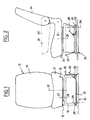
- Fig. 2 is shown in phantom in the folder 14 in the folded position that the rear face 40 of the folder 14 can be used as a table thanks to sufficient rigidity which can be given to it by a plastic plate.
- the identical elements in this fig. 2 bear the same references as those in FIG. 1. It can be seen that the axis 20 is in a centered position relative to the seat 12 and to the sole 32.
- the row of seats considered comprises two seats 10 and 100, the seat 100 being of the conventional type fitted with runners 128 directly fixed to the floor 42 of the vehicle and a pivoting device 116 of a known type.
- the slides 128 of this seat 100 are oriented along the longitudinal axis of the vehicle indicated by the arrow 44, that is to say parallel to the sides of the vehicle referenced 46 and 48.
- the side 48 comprises a side access door 50 , the seats 10 and 100 being arranged substantially in line with this door 50.
- the seat 100 given its mounting on the slides 128, can move back and forth parallel to the direction 44, these two movements being symbolized by the arrow 52.
- the seat 10 is provided with a second pivoting device 36 around a second vertical axis 34 and this device comprises a pivot 54, pads 56, 58 and 60 as well as a rail 62.
- This rail 62 has a shape of semicircle whose diameter is oriented perpendicular to direction 44.
- the pivot axis 34 and the pivot 54 are coaxial and located near the corner of a rear angle of the sole, and on the floor at a distance from the side 48 substantially equal to the width of the seat.
- the end pads 56 and 60 are themselves arranged in the two opposite angles adjacent to the angle in which the pivot 54 is located and these pads are called holding pads.
- the third pad 58 is called the stabilization pad.
- the rail portion 62 located between the pads 60 and 56 is a quarter of a circle.
- the rail 62 has a C profile and is fixed to the floor by screws 72, the opening of the C being oriented upwards.
- Each T-shaped pad is received in the C-shaped rail with which it cooperates by sliding thanks to a support ring 74 which cooperates by sliding with the upper face of the C-shaped rail.
- T is fixed on the sole 32 using screws 76. In this FIG. 4, the slides 28 also fixed on this sole are shown.
- the sole can pivot around the axis 34 by means of the pivot 54, the axis 34 corresponding to the center of the semicircle formed by the rail 62.
- the pads can slide in the rail 62 while being retained by the profile in T in this same rail, thus avoiding any tilting of the seat.
- the stabilization pad 58 facilitates the movement of the pads in the rail by ensuring better guidance, better stabilization of the seat, and also a better distribution of the weight.
- the seat can take two positions, central and lateral, and in FIG. 3 is shown in these two positions, respectively at 20 and 20 ′, the axis of rotation of the seat relative to the frame 18 carried by the sole 32; position 20 ′ is obtained by rotation of the sole 32 around the axis 34, with sliding of the pads 56, 58 and 60 in the rail 62, the pad 56 abutting against the end 62a of the rail 62 while the pad 60 occupies the initial position of pad 56.
- the angle alpha of the pivoting of the sole between its central position and its lateral position is an angle substantially of 90 °.
- the position of the slides 28 has been shown in broken lines after the sole 38 has rotated 90 °. These slides 28 are then perpendicular to the side 48, that is to say perpendicular to the rear side access door 50.
- the arrows 78 and 80 respectively materialize the possible translational movements thanks to the slides in the two positions of the axis 20 and 20 ′.
- the sole In its central position, the sole is spaced on the side 48 by a distance substantially equal to the width of the seat, while, in its lateral position, it is close to the side 48 and, therefore, of the rear side access door. 50.
- the arrow 82 materializes the rotation of the sole 32 while the arrow 84 materializes the possibility of rotation through 360 ° thanks to the first pivoting device 16.
- FIGS. 5A to 5E Such an arrangement therefore allows a large number of combinations, some of which are shown in FIGS. 5A to 5E in the case where the vehicle in question comprises a row of front seats 86, a row of middle seats 88 with two independent seats 10 and 100 as well as a row of rear seats 90 comprising, in the example shown, only one and even bench.
- the seat 100 includes a backrest 140, a seat 120, slides 128 and a single rotation device 160.
- the middle seats 10 and 100 are arranged in a conventional configuration according to which access to the rear seat 90 is facilitated by the clearance of the floor to the right of the door 50.
- the adjustment in front / rear translation is always possible on seat 10 since the slides 28 are oriented parallel to direction 44.
- Fig. 5A shows the two middle seats 10 Oret 100 in an arrangement according to which the seat 10 is moved away from the seat 100, this position being obtained by a double movement of the same seat, namely a rotation of the sole 32 around the axis 34 which brings the axis 20 to position 20 ′ and a rotation of the first pivoting device 16 anti-clockwise by a quarter of a turn, so as to return the seat to its initial orientation.
- the seat 10 is found in the position shown in Figure 5B, namely that the backrest 14 of the seat 10 is parallel to the side 48 of the vehicle and adjacent to it.
- the seat 100 By rotating the seat 100 a quarter turn clockwise, it is possible to obtain a configuration in which the seats 10 and 100 are opposite and allow with the row of rear seats 90, to constitute a "living room".
- Fig. 5D there is shown the seat 10 in a configuration according to which the backrest 14 has been lowered as indicated by a dashed line in FIG. 2 thus constituting a table usable by the passenger of the seat 100 as well as the passengers of the row of seats 90.
- This arrangement of the backrest 14 forming a table can also be applied in the configuration shown in FIG. 5C or 5A when the seat 10 is vacant.
- the present invention also makes it possible to propose a particular configuration by virtue of the orientation of the slides 28.
- the slides 28 are oriented perpendicular to the access door 50.
- the seat 10 can be translated on its slides 28 and with sufficient clearance, the seat 12 of the seat 10 can be advanced from the right of the outer limit on the side 48, through the opening released by the access door.
- the arrangement according to the invention has many advantages, especially in the 5E configuration. This arrangement makes it possible to facilitate the installation of disabled passengers since the seat 10 is easily accessible and the movements to bring it back to the initial position can be carried out with the passenger seated on the seat 10.
- the vehicle allows seven people to be able to meet.
- the various maneuvers for changing the configuration are very simple and few in number and in all cases only call for maneuvers from one and the same seat.
- the seat 10 retains its possibility of front-rear adjustment of so as to adapt to the morphology of the passenger, as for the rail 62 its size is very limited and does not cause any discomfort at the location of the feet of the passengers when the seats are oriented parallel to the direction 44.
Abstract
Description
La présente invention a pour objet un agencement de siège sur un plancher de véhicule et plus particulièrement celui d'un siège arrière situé au droit de la porte latérale d'accès arrière.The present invention relates to a seat arrangement on a vehicle floor and more particularly that of a rear seat located to the right of the rear side access door.
Certains véhicules comprennent deux rangées de sièges ou plus disposés sur leur plancher. Dans le cas de trois rangées de sièges, un problème se pose quant à l'accessibilité de la troisième rangée car les constructeurs ne prévoient généralement qu'une seule porte d'accès pour les deux rangées de sièges arrière. Dans d'autres véhicules il n'existe que deux rangées de sièges mais il est nécessaire de pouvoir accéder à l'arrière du véhicule lorsque celui-ci est aménagé en camping-car par exemple.Some vehicles have two or more rows of seats on their floor. In the case of three rows of seats, a problem arises as to the accessibility of the third row since the manufacturers generally provide only one access door for the two rows of rear seats. In other vehicles there are only two rows of seats but it is necessary to be able to access the rear of the vehicle when it is fitted out in a motorhome for example.
Le brevet US 4 341 415, a pour objet un aménagement de véhicule automobile dans lequel sont disposées trois rangées de sièges dont les deux dernières rangées ne sont accessibles que par une seule et même porte disposée sensiblement au droit de la deuxième rangée. Les deux sièges médians sont disposés sur des glissières de façon connue mais ces glissières sont disposées, pour le siège au droit de la porte, suivant une orientation de 60° par rapport à l'axe longitudinal du véhicule, tandis que pour l'autre elles sont disposées suivant l'axe longitudinal du véhicule.US Patent 4,341,415, relates to an arrangement of a motor vehicle in which are arranged three rows of seats, the last two rows of which are accessible only by one and the same door disposed substantially in line with the second row. The two middle seats are arranged on slides in a known manner but these slides are arranged, for the seat to the right of the door, in an orientation of 60 ° relative to the longitudinal axis of the vehicle, while for the other they are arranged along the longitudinal axis of the vehicle.
Un tel aménagement n'est possible que sur certains véhicules dans lesquels la place disponible est suffisamment importante. En effet, il est nécessaire lorsque l'on recule le deuxième siège médian, de pouvoir disposer d'une distance suffisante entre les sièges avant et ce siège médian pour pouvoir positionner le premier siège médian. De plus, durant cette manoeuvre il est nécessaire de faire bouger successi vement deux sièges et ceci au moins deux fois chacun, ce qui conduit à un minimum de quatre opérations pour dégager l'espace situé au droit de la porte latérale arrière. Enfin, il est à remarquer que le siège disposé sur des rails de guidage orientés obliquement par rapport à l'axe de déplacement du véhicule ne dispose plus de son réglage avant/arrière permettant d'ajuster la position de ce siège par rapport au siège avant en fonction de la morphologie de l'utilisateur.Such an arrangement is only possible on certain vehicles in which the available space is sufficiently large. Indeed, it is necessary when moving the second median seat back, to be able to have a sufficient distance between the front seats and this median seat to be able to position the first median seat. In addition, during this maneuver it is necessary to move successi two seats at least twice each, which leads to a minimum of four operations to clear the space located to the right of the rear side door. Finally, it should be noted that the seat arranged on guide rails oriented obliquely to the axis of movement of the vehicle no longer has its front / rear adjustment making it possible to adjust the position of this seat relative to the front seat. depending on the morphology of the user.
Le but de la présente invention est de proposer un agencement de siège qui pallie les inconvénients évoqués ci-dessus tout en proposant une modularité de la disposition des sièges encore plus importante.The object of the present invention is to propose a seat arrangement which overcomes the drawbacks mentioned above while proposing an even greater modularity in the arrangement of the seats.
A cet effet, l'agencement, sur un plancher de véhicule, d'un siège situé derrière un siège avant au droit d'une porte latérale d'accès d'un véhicule comportant une assise munie d'un premier dispositif de pivotement, sur une semelle sensiblement carrée mobile par rapport au plancher, autour d'un premier axe vertical de rotation passant sensiblement par le centre de l'assise, caractérisé en ce que la semelle comprend un second dispositif de pivotement par rapport au plancher autour d'un second axe vertical de rotation excentré par rapport au premier axe et situé à une distance de la porte latérale d'accès sensiblement égale à la largeur d'un siège.To this end, the arrangement, on a vehicle floor, of a seat situated behind a front seat in line with a side access door of a vehicle comprising a seat provided with a first pivoting device, on a substantially square sole movable relative to the floor, around a first vertical axis of rotation passing substantially through the center of the seat, characterized in that the sole comprises a second pivoting device relative to the floor around a second vertical axis of rotation eccentric with respect to the first axis and situated at a distance from the side access door substantially equal to the width of a seat.
Selon une autre caractéristique de l'invention le second axe de rotation est disposé sur un bord latéral de la semelle et plus particulièrement dans un angle de cette semelle.According to another characteristic of the invention, the second axis of rotation is arranged on a lateral edge of the sole and more particularly in a corner of this sole.
L'agencement selon l'invention est en outre caractérisé en ce que le second dispositif comprend des moyens de verrouillage de la semelle par rapport au plancher dans deux positions faisant entre elles un angle de 90°.The arrangement according to the invention is further characterized in that the second device comprises means for locking the sole relative to to the floor in two positions making an angle of 90 ° between them.
En outre le second dispositif comprend au moins deux patins fixés à la semelle et reçus à glissement dans un rail courbe fixé sur le plancher et une articulation dont l'axe de rotation est le second axe de rotation, le rail courbe selon une autre caractéristique étant une portion de cercle dont la corde est orientée perpendiculairement à l'axe longitudinal du véhicule.In addition, the second device comprises at least two pads fixed to the sole and received with sliding in a curved rail fixed on the floor and a joint whose axis of rotation is the second axis of rotation, the curved rail according to another characteristic being a portion of a circle whose cord is oriented perpendicular to the longitudinal axis of the vehicle.
Selon une autre caractéristique le premier dispositif de pivotement est monté sur des glissières rectilignes fixées sur la semelle et orientées parallèlement aux bords de celle-ci.According to another characteristic, the first pivoting device is mounted on rectilinear slides fixed on the sole and oriented parallel to the edges of the latter.
L'invention va être décrite ci-dessous plus en détail en se référant aux dessins annexés sur lesquels :
- - la Fig. 1 est une vue de face d'un siège utilisé pour l'agencement selon l'invention ;
- - la Fig. 2 est une vue latérale du siège utilisé pour l'agencement selon l'invention ;
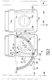
- - la Fig. 3 est une vue de dessus de l'agencement de sièges selon l'invention :
- - la Fig. 4 est une vue en coupe suivant la ligne 4-4 de la Fig. 3 ; et
- - les Fig. 5A à 5E représentent des schémas de configurations possibles à l'aide de l'agencement selon l'invention.
- - Fig. 1 is a front view of a seat used for the arrangement according to the invention;
- - Fig. 2 is a side view of the seat used for the arrangement according to the invention;
- - Fig. 3 is a top view of the arrangement of seats according to the invention:
- - Fig. 4 is a sectional view along line 4-4 of FIG. 3; and
- - Figs. 5A to 5E represent diagrams of possible configurations using the arrangement according to the invention.
Le siège 10 selon l'invention comporte de façon connue une assise 12 et un dossier 14 inclinable par rapport à l'assise. Ce siège est monté pivotant grâce à un premier dispositif de pivotement 16 par rapport à un bâti 18 sensiblement rectangulaire, l'axe vertical de rotation 20 du premier dispositif de pivotement étant sensiblement centré par rapport à l'assise 12 et au bâti 18. Ce premier dispositif de pivotement comporte de façon connue deux châssis 22 et 24 mobiles en rotation l'un par rapport à l'autre, le mouvement de rotation pouvant être bloqué à l'aide d'un levier 26 qui solidarise les deux châssis 22 et 24.The
Par ailleurs, le bâti 18 est monté déplaçable en translation grâce à des glissières 28 parallèles à deux de ses côtés. L'immobilisation du bâti 18 par rapport aux glissières est obtenue à l'aide d'un levier 30 de verrouillage. Les parties fixes des glissières 28 sont montées sur une semelle 32 qui a une forme sensiblement carrée et elle est elle-même mobile en rotation autour de l'axe vertical 34 d'un second dispositif de pivotement 36. Le blocage en rotation de ce deuxième dispositif de pivotement par rapport au plancher est obtenu à l'aide d'un levier 38 qui se bloque dans des crans ménagés dans ce plancher (non représenté).Furthermore, the
Sur la Fig. 2 on a représenté en trait mixte le dossier 14 en position rabattue selon laquelle la face arrière 40 de ce dossier 14 est utilisable comme table grâce à une rigidité suffisante qui peut lui être conférée par une plaque en matière plastique. Les éléments identiques de cette Fig. 2 portent les mêmes références que celles de la Fig. 1. On constate que l'axe 20 est en position centrée par rapport à l'assise 12 et à la semelle 32.In Fig. 2 is shown in phantom in the
L'agencement selon l'invention est représenté en détail à la Fig. 3. La rangée de sièges considérée comprend deux sièges 10 et 100, le siège 100 étant du type classique muni de glissières 128 directement fixées sur le plancher 42 du véhicule et d'un dispositif de pivotement 116 d'un type connu. Les glissières 128 de ce siège 100 sont orientées suivant l'axe longitudinal du véhicule indiqué par la flèche 44, c'est-à-dire parallèlement aux côtés du véhicule référencés 46 et 48. Le côté 48 comprend une porte latérale d'accès 50, les sièges 10 et 100 étant disposés sensiblement au droit de cette porte 50.The arrangement according to the invention is shown in detail in FIG. 3. The row of seats considered comprises two
Le siège 100, compte tenu de son montage sur les glissières 128, peut se déplacer d'avant en arrière parallèlement à la direction 44, ces deux mouvements étant symbolisés par la flèche 52.The
Le siège 10 est muni d'un second dispositif de pivotement 36 autour d'un second axe vertical 34 et ce dispositif comprend un pivot 54, des patins 56, 58 et 60 ainsi qu'un rail 62. Ce rail 62 a une forme de demi-cercle dont le diamètre est orienté perpendiculairement à la direction 44.The
L'axe 34 de pivotement et le pivot 54 sont coaxiaux et situés près du coin d'un angle arrière de la semelle, et sur le plancher à une distance du côté 48 sensiblement égale à la largeur du siège. Les patins d'extrémités 56 et 60 sont eux disposés dans les deux angles opposés adjacents à l'angle dans lequel est situé le pivot 54 et ces patins sont appelés patins de maintien. Le troisième patin 58 est appelé patin de stabilisation. La portion de rail 62 située entre les patins 60 et 56 est un quart de cercle.The
Sur la coupe représentée Fig. 4 on a détaillé le deuxième dispositif de pivotement et l'on retrouve le pivot 54 sur lequel la semelle 32 s'articule à l'aide d'un axe vissé 64 , le pivot 54 étant lui-même fixé par les vis 66 au plancher 42 du véhicule.In the section shown in Fig. 4 the second pivoting device has been detailed and there is the
En 68 et 70 on a représenté les couches de matériaux connus et utilisés dans un véhicule automobile pour assurer l'insonorisation et l'esthétique du plancher intérieur.In 68 and 70, the layers of known materials used in a motor vehicle are shown to provide soundproofing and the aesthetics of the interior floor.
Le rail 62 a un profil en C et il est fixé au plancher par des vis 72, l'ouverture du C étant orientée vers le haut. Chaque patin en forme de T est reçu dans le rail en forme de C avec lequel il coopère par glissement grâce à une bague d'appui 74 qui vient coopérer par glissement avec la face supérieure du rail en forme de C. Ce patin en forme de T est fixé sur la semelle 32 à l'aide de vis 76. Sur cette Figure 4 on a également représenté les glissières 28 fixées sur cette semelle.The
La semelle peut pivoter autour de l'axe 34 par l'intermédiaire du pivot 54, l'axe 34 correspondant au centre du demi-cercle formé par le rail 62. Les patins peuvent coulisser dans le rail 62 tout en étant retenus par le profilé en T dans ce même rail, évitant ainsi tout basculement du siège.The sole can pivot around the
Le patin de stabilisation 58 facilite le mouvement des patins dans le rail en assurant un meilleur guidage, une meilleure stabilisation du siège, et également une meilleure répartition du poids.The stabilization pad 58 facilitates the movement of the pads in the rail by ensuring better guidance, better stabilization of the seat, and also a better distribution of the weight.
Le siège peut prendre deux positions, centrale et latérale, et sur la Fig. 3 on a représenté dans ces deux positions, respectivement en 20 et en 20′, l'axe de rotation du siège par rapport au bâti 18 porté par la semelle 32 ; la position 20′ est obtenue par rotation de la semelle 32 autour de l'axe 34, avec glissement des patins 56, 58 et 60 dans le rail 62, le patin 56 venant en butée contre l'extrémité 62a du rail 62 tandis que le patin 60 occupe la position initiale du patin 56.The seat can take two positions, central and lateral, and in FIG. 3 is shown in these two positions, respectively at 20 and 20 ′, the axis of rotation of the seat relative to the
On remarque que l'angle alpha du pivotement de la semelle entre sa position centrale et sa position latérale est un angle sensiblement de 90°. On a représenté en trait mixte la position des glissières 28 après que la semelle 38 ait effectué une rotation de 90°. Ces glissières 28 sont alors perpendiculaires au côté 48, c'est-à-dire perpendiculaires à la porte latérale d'accès arrière 50. Les flèches 78 et 80 matérialisent respectivement les mouvements de translation possibles grâce aux glissières dans les deux positions de l'axe 20 et 20′.It is noted that the angle alpha of the pivoting of the sole between its central position and its lateral position is an angle substantially of 90 °. The position of the
Dans sa position centrale, la semelle est espacée du côté 48 d'une distance sensiblement égale à la largeur du siège, tandis que, dans sa position latérale, elle est proche du côté 48 et, donc, de la porte latérale d'accès arrière 50. La flèche 82 matérialise la rotation de la semelle 32 tandis que la flèche 84 matérialise la possibilité de rotation sur 360° grâce au premier dispositif de pivotement 16.In its central position, the sole is spaced on the
Un tel agencement permet donc un grand nombre de combinaisons dont certaines sont représentées aux Fig. 5A à 5E dans le cas où le véhicule considéré comporte une rangée de siège avant 86, une rangée de sièges médians 88 avec deux sièges indépendants 10 et 100 ainsi qu'une rangée de sièges arrière 90 comportant, dans l'exemple représenté, une seule et même banquette. Le siège 100 comprend un dossier 140, une assise 120, des glissières 128 et un dispositif unique de rotation 160.Such an arrangement therefore allows a large number of combinations, some of which are shown in FIGS. 5A to 5E in the case where the vehicle in question comprises a row of
Sur la Fig. 3, les sièges médians 10 et 100 sont disposés dans une configuration classique selon laquelle l'accès au siège arrière 90 est facilité par le dégagement du plancher au droit de la porte 50. Le réglage en translation avant/arrière est toujours possible sur le siège 10 puisque les glissières 28 sont orientées parallèlement à la direction 44.In Fig. 3, the
La Fig. 5A montre les deux sièges médians 10 Oret 100 dans une disposition suivant laquelle le siège 10 est écarté du siège 100, cette position étant obtenue par un double mouvement du même siège, à savoir une rotation de la semelle 32 autour de l'axe 34 qui amène l'axe 20 en position 20′ et une rotation du premier dispositif de pivotement 16 dans le sens contraire des aiguilles d'une montre d'un quart de tour, de façon à ramener le siège dans son orientation initiale.Fig. 5A shows the two
A la suite d'un quart de tour supplémentaire du premier dispositif de pivotement autour de l'axe 20′, le siège 10 se retrouve dans la position représentée sur la Figure 5B, à savoir que le dossier 14 du siège 10 est parallèle au côté 48 du véhicule et adjacent à celui-ci. Moyennant une rotation d'un quart de tour du siège 100 dans le sens des aiguilles d'une montre, il est possible d'obtenir une configuration selon laquelle les sièges 10 et 100 sont en vis-à-vis et permettent avec la rangée de sièges arrière 90, de constituer un "salon".Following an additional quarter turn of the first pivoting device around the
Sur la Fig. 5C et moyennant la rotation d'un demi-tour de chacun des sièges avant il est possible de réaliser une configuration "salon" faisant participer l'ensemble des passagers qui occupent les différents sièges du véhicule, y compris les sièges avant.In Fig. 5C and by means of the rotation of a half-turn of each of the front seats it is possible to produce a "lounge" configuration involving all of the passengers who occupy the various seats of the vehicle, including the front seats.
Sur la Fig. 5D on a représenté le siège 10 dans une configuration selon laquelle le dossier 14 a été abaissé ainsi que cela est indiqué en trait mixte sur la Fig.2 constituant ainsi une table utilisable par le passager du siège 100 ainsi que les passagers de la rangée de sièges 90. Cette disposition du dossier 14 formant table peut également être appliquée dans la configuration représentée à la Fig.5C ou 5A lorsque le siège 10 est vacant.In Fig. 5D there is shown the
La présente invention permet également de proposer une configuration particulière grâce à l'orientation des glissières 28. En effet, lorsque l'axe de rotation 20 est en position 20′, les glissières 28 sont orientées perpendiculairement à la porte d'accès 50.The present invention also makes it possible to propose a particular configuration by virtue of the orientation of the
A partir de sa position centrale telle que représentée à la Fig.3, après rotation de la semelle 32 d'un quart de tour de façon à amener l'axe 20 en position 20′, le siège 10 peut être translaté sur ses glissières 28 et moyennant un débattement suffisant, l'assise 12 du siège 10 peut être avancée du droit de la limite extérieure du côté 48, à travers l'ouverture libérée par la porte d'accès.From its central position as shown in Fig.3, after rotation of the sole 32 of a quarter turn so as to bring the
L'agencement selon l'invention présente de nombreux avantages notamment dans la configuration 5E. Cet agencement permet en effet de faciliter l'installation de passagers handicapés puisque le siège 10 est facilement accessible et que les mouvements pour le ramener en position initiale peuvent s'effectuer avec le passager assis sur le siège 10.The arrangement according to the invention has many advantages, especially in the 5E configuration. This arrangement makes it possible to facilitate the installation of disabled passengers since the
D'autre part dans la configuration représentée à la Fig.5C, le véhicule permet à sept personnes de pouvoir se réunir.On the other hand in the configuration shown in Fig.5C, the vehicle allows seven people to be able to meet.
On remarque également que les différentes manoeuvres pour changer de configuration sont très simples et peu nombreuses et elles ne font appel dans tous les cas qu'à des manoeuvres d'un seul et même siège. Dans la position représentée Fig.3 le siège 10 conserve sa possibilité de réglage avant - arrière de façon à s'adapter à la morphologie du passager, quant au rail 62 son encombrement est très limité et ne provoque aucune gêne à l'emplacement des pieds des passagers lorsque les sièges sont orientés parallèlement à la direction 44.It is also noted that the various maneuvers for changing the configuration are very simple and few in number and in all cases only call for maneuvers from one and the same seat. In the position shown in Fig.3 the
Claims (7)
Applications Claiming Priority (2)
| Application Number | Priority Date | Filing Date | Title |
|---|---|---|---|
| FR8806800 | 1988-05-20 | ||
| FR8806800A FR2631591B1 (en) | 1988-05-20 | 1988-05-20 | ARRANGEMENT OF A SEAT ON A VEHICLE FLOOR |
Publications (3)
| Publication Number | Publication Date |
|---|---|
| EP0343026A2 true EP0343026A2 (en) | 1989-11-23 |
| EP0343026A3 EP0343026A3 (en) | 1990-03-14 |
| EP0343026B1 EP0343026B1 (en) | 1993-03-24 |
Family
ID=9366499
Family Applications (1)
| Application Number | Title | Priority Date | Filing Date |
|---|---|---|---|
| EP19890401111 Expired - Lifetime EP0343026B1 (en) | 1988-05-20 | 1989-04-20 | Arrangement of a seat on a vehicle floor |
Country Status (3)
| Country | Link |
|---|---|
| EP (1) | EP0343026B1 (en) |
| DE (1) | DE68905521T2 (en) |
| FR (1) | FR2631591B1 (en) |
Cited By (15)
| Publication number | Priority date | Publication date | Assignee | Title |
|---|---|---|---|---|
| GB2238828A (en) * | 1989-12-04 | 1991-06-12 | Sears Mfg Co | Pivot for swivelling seat |
| US5474353A (en) * | 1993-12-01 | 1995-12-12 | Hoover Universal, Inc. | Pivoting seat cushion arrangement for vehicle seat assemblies |
| FR2759648A1 (en) * | 1997-02-18 | 1998-08-21 | Renault | Dual=purpose passenger seat for e.g. motor vehicles serving as a mobile office |
| FR2775637A1 (en) * | 1998-03-05 | 1999-09-10 | Peugeot | Adjuster for independent rear seats in vehicles |
| EP1095813A1 (en) * | 1994-12-07 | 2001-05-02 | Ab Volvo | Vehicle seat |
| EP1223072A3 (en) * | 2001-01-16 | 2003-01-02 | AGUTI PRODUKTENTWICKLUNG & DESIGN GMBH | Seat assembly particularly for camper vans |
| US6814174B2 (en) * | 2003-01-23 | 2004-11-09 | Ingersoll-Rand Company | Telescoping seat assembly for a construction vehicle |
| DE102006022732A1 (en) * | 2006-05-12 | 2007-11-15 | Johnson Controls Gmbh | Seat arrangement for motor vehicle, has seat shift element with lower part arranged rigidly on vehicle |
| DE102007016462A1 (en) * | 2007-03-29 | 2008-10-02 | Veigel Gmbh & Co. Kg | Seat frame for vehicle, has displacement device with longitudinal and transverse centerline, where displacement device has lower part and upper part that is adjustably arranged against lower part |
| DE19915220B4 (en) * | 1999-04-03 | 2009-10-22 | Bayerische Motoren Werke Aktiengesellschaft | Device for fastening rear seats in a motor vehicle |
| DE102008059999A1 (en) * | 2008-12-02 | 2010-06-10 | GM Global Technology Operations, Inc., Detroit | Motor vehicle seat with an adjustment |
| DE102010021066A1 (en) * | 2010-05-19 | 2011-11-24 | Gm Global Technology Operations Llc (N.D.Ges.D. Staates Delaware) | Device for carrying and adjusting seat in vehicle, has cross beam, which is guided in one or multiple seat tracks |
| FR2977202A1 (en) * | 2011-06-28 | 2013-01-04 | Antolin Grupo Ing Sa | Seat for use in automobile, has lifting unit conceived to move base between low position and high position, and pivoting unit conceived to pivot base around pivot axis when base is positioned in high position |
| GB2547036A (en) * | 2016-02-05 | 2017-08-09 | Ford Global Tech Llc | Method of positioning a vehicle seat |
| JP2018188149A (en) * | 2018-09-06 | 2018-11-29 | テイ・エス テック株式会社 | Rotary seat device |
Families Citing this family (10)
| Publication number | Priority date | Publication date | Assignee | Title |
|---|---|---|---|---|
| DE29518853U1 (en) * | 1995-10-13 | 1997-02-13 | Mohr Ernst Dipl Ing | Seat arrangement for passenger vehicles or the like. |
| DE10120769B4 (en) * | 2001-04-27 | 2012-08-16 | GM Global Technology Operations LLC (n. d. Ges. d. Staates Delaware) | Pivoting seat arrangement for a vehicle with a pivoting drive |
| DE102004022706B4 (en) | 2004-05-05 | 2007-03-29 | Johnson Controls Gmbh | Vehicle seat with entry-level facilitation |
| DE102005041735A1 (en) * | 2005-09-02 | 2007-03-08 | Daimlerchrysler Ag | Swivelable seat arrangement for use in driving cab of commercial vehicle, has two circular-arc shaped guideways provided in receiving area of seat, where seat is displaced in guideways and securely locked in its swiveling end positions |
| DE102005050128B4 (en) * | 2005-09-08 | 2014-10-09 | Bayerische Motoren Werke Aktiengesellschaft | motor vehicle |
| DE102006031466B4 (en) * | 2005-09-08 | 2014-11-20 | Bayerische Motoren Werke Aktiengesellschaft | Seat for a motor vehicle |
| DE102007003286A1 (en) | 2007-01-23 | 2008-07-24 | GM Global Technology Operations, Inc., Detroit | Seat e.g. rear seat, part moving device, for motor vehicle, has moving unit comprising moving mechanism moved transverse to longitudinal direction and with rail system for moving part of seat into linear direction i.e. transverse direction |
| DE102008048360A1 (en) * | 2008-09-22 | 2010-03-25 | Aguti Produktentwicklung & Design Gmbh | Seating unit has vehicle seat and rotating unit for rotating vehicle seat around vertical rotational axis in use position and pivoting arrangement is provided for pivoting vehicle seat together with rotating unit |
| DE102011103225B4 (en) * | 2011-06-01 | 2013-04-25 | Keiper Gmbh & Co. Kg | vehicle seat |
| DE102017206941A1 (en) * | 2017-04-25 | 2018-10-25 | Robert Bosch Gmbh | seat adjustment |
Citations (5)
| Publication number | Priority date | Publication date | Assignee | Title |
|---|---|---|---|---|
| FR1222035A (en) * | 1958-03-17 | 1960-06-07 | Rockwell Standard Co | Advanced seat, especially for motor vehicles |
| DE2545742A1 (en) * | 1975-10-11 | 1977-04-14 | Rudolf Siebeneichler | DEVICE FOR SWIVELING IN AND OUT OF SINGLE SEATS |
| US4341415A (en) * | 1978-12-23 | 1982-07-27 | Westfalia-Werke Franz Knobel & Sohne Kg | Vehicle having at least two rows of tandem seats |
| WO1985005081A1 (en) * | 1984-05-08 | 1985-11-21 | Roy Mervyn Bailey | Swivellable seat for motor vehicles |
| WO1987001661A1 (en) * | 1985-09-18 | 1987-03-26 | Melvyn John Goodall | Movable seat arrangement |
-
1988
- 1988-05-20 FR FR8806800A patent/FR2631591B1/en not_active Expired - Fee Related
-
1989
- 1989-04-20 DE DE1989605521 patent/DE68905521T2/en not_active Expired - Fee Related
- 1989-04-20 EP EP19890401111 patent/EP0343026B1/en not_active Expired - Lifetime
Patent Citations (5)
| Publication number | Priority date | Publication date | Assignee | Title |
|---|---|---|---|---|
| FR1222035A (en) * | 1958-03-17 | 1960-06-07 | Rockwell Standard Co | Advanced seat, especially for motor vehicles |
| DE2545742A1 (en) * | 1975-10-11 | 1977-04-14 | Rudolf Siebeneichler | DEVICE FOR SWIVELING IN AND OUT OF SINGLE SEATS |
| US4341415A (en) * | 1978-12-23 | 1982-07-27 | Westfalia-Werke Franz Knobel & Sohne Kg | Vehicle having at least two rows of tandem seats |
| WO1985005081A1 (en) * | 1984-05-08 | 1985-11-21 | Roy Mervyn Bailey | Swivellable seat for motor vehicles |
| WO1987001661A1 (en) * | 1985-09-18 | 1987-03-26 | Melvyn John Goodall | Movable seat arrangement |
Cited By (21)
| Publication number | Priority date | Publication date | Assignee | Title |
|---|---|---|---|---|
| GB2238828A (en) * | 1989-12-04 | 1991-06-12 | Sears Mfg Co | Pivot for swivelling seat |
| GB2238828B (en) * | 1989-12-04 | 1993-10-06 | Sears Mfg Co | Swivel seat,especially for vehicles |
| US5474353A (en) * | 1993-12-01 | 1995-12-12 | Hoover Universal, Inc. | Pivoting seat cushion arrangement for vehicle seat assemblies |
| EP1095813A1 (en) * | 1994-12-07 | 2001-05-02 | Ab Volvo | Vehicle seat |
| FR2759648A1 (en) * | 1997-02-18 | 1998-08-21 | Renault | Dual=purpose passenger seat for e.g. motor vehicles serving as a mobile office |
| FR2775637A1 (en) * | 1998-03-05 | 1999-09-10 | Peugeot | Adjuster for independent rear seats in vehicles |
| DE19915220B4 (en) * | 1999-04-03 | 2009-10-22 | Bayerische Motoren Werke Aktiengesellschaft | Device for fastening rear seats in a motor vehicle |
| EP1223072A3 (en) * | 2001-01-16 | 2003-01-02 | AGUTI PRODUKTENTWICKLUNG & DESIGN GMBH | Seat assembly particularly for camper vans |
| US6814174B2 (en) * | 2003-01-23 | 2004-11-09 | Ingersoll-Rand Company | Telescoping seat assembly for a construction vehicle |
| DE102006022732B4 (en) * | 2006-05-12 | 2013-05-29 | Johnson Controls Gmbh | Seat arrangement for a motor vehicle |
| DE102006022732A1 (en) * | 2006-05-12 | 2007-11-15 | Johnson Controls Gmbh | Seat arrangement for motor vehicle, has seat shift element with lower part arranged rigidly on vehicle |
| DE102007016462A1 (en) * | 2007-03-29 | 2008-10-02 | Veigel Gmbh & Co. Kg | Seat frame for vehicle, has displacement device with longitudinal and transverse centerline, where displacement device has lower part and upper part that is adjustably arranged against lower part |
| DE102007016462B4 (en) * | 2007-03-29 | 2012-10-18 | Veigel Gmbh & Co. Kg | Seat frame for a vehicle |
| DE102008059999A1 (en) * | 2008-12-02 | 2010-06-10 | GM Global Technology Operations, Inc., Detroit | Motor vehicle seat with an adjustment |
| US8408651B2 (en) | 2008-12-02 | 2013-04-02 | GM Global Technology Operations LLC | Motor vehicle seat with an adjusting device |
| DE102010021066A1 (en) * | 2010-05-19 | 2011-11-24 | Gm Global Technology Operations Llc (N.D.Ges.D. Staates Delaware) | Device for carrying and adjusting seat in vehicle, has cross beam, which is guided in one or multiple seat tracks |
| FR2977202A1 (en) * | 2011-06-28 | 2013-01-04 | Antolin Grupo Ing Sa | Seat for use in automobile, has lifting unit conceived to move base between low position and high position, and pivoting unit conceived to pivot base around pivot axis when base is positioned in high position |
| GB2547036A (en) * | 2016-02-05 | 2017-08-09 | Ford Global Tech Llc | Method of positioning a vehicle seat |
| GB2547036B (en) * | 2016-02-05 | 2018-08-01 | Ford Global Tech Llc | Method of positioning a vehicle seat |
| US10081272B2 (en) | 2016-02-05 | 2018-09-25 | Ford Global Technologies, Llc | Method of positioning a vehicle seat |
| JP2018188149A (en) * | 2018-09-06 | 2018-11-29 | テイ・エス テック株式会社 | Rotary seat device |
Also Published As
| Publication number | Publication date |
|---|---|
| EP0343026A3 (en) | 1990-03-14 |
| FR2631591B1 (en) | 1990-08-24 |
| EP0343026B1 (en) | 1993-03-24 |
| FR2631591A1 (en) | 1989-11-24 |
| DE68905521D1 (en) | 1993-04-29 |
| DE68905521T2 (en) | 1993-11-04 |
Similar Documents
| Publication | Publication Date | Title |
|---|---|---|
| EP0343026B1 (en) | Arrangement of a seat on a vehicle floor | |
| EP1345810B1 (en) | Seat convertible into a bed, in particular for aircraft | |
| EP1366987B1 (en) | Seat convertible into bed having a deformable armrest | |
| FR2920011A1 (en) | SWIVEL SEAT FOR AN AIRCRAFT AND ASSEMBLY OF SUCH SEATS | |
| FR2870795A1 (en) | VEHICLE SEAT AND VEHICLE EQUIPPED WITH SUCH A SEAT | |
| EP0336819A1 (en) | Folding seat, particularly the rear seat for a motor vehicle | |
| FR2929179A1 (en) | Motor vehicle's seat, has advancement control unit to place fixation mechanism in inactive position to displace backrest with respect to chassis from nominal position towards forward position by rotation of foot with respect to chassis | |
| FR3083174A1 (en) | MOTOR VEHICLE SEAT | |
| FR2524285A1 (en) | Convertible seat for vehicle - has back rest and seat folding down and incorporates two levers linked to bearings, with slides | |
| CA2284448C (en) | Enhanced movement swivel seat, including for railway vehicles | |
| EP0626288B1 (en) | Wrapping seat for vehicle | |
| EP1467883A1 (en) | Rear shelf for motor vehicle equipped with a folding roof | |
| EP0628447B1 (en) | Articulation device for vehicle seat | |
| EP4255806A1 (en) | Console for a seat unit provided with a movable closing plate for a storage housing | |
| FR2933345A1 (en) | SEAT OF A MOTOR VEHICLE AND VEHICLE PROVIDED WITH SUCH A SEAT | |
| FR2811947A1 (en) | Seat for motor vehicle has neutralization control for seat pivot lock mounted concentrically around pivot | |
| EP1414668B1 (en) | Adjustable vehicle bench seat | |
| FR2897024A1 (en) | Passenger seat for motor vehicle, has backrest comprising central inset with three sides and peripheral crown surrounding central inset on its three sides, where peripheral crown is mobile with respect to central inset | |
| FR2902724A1 (en) | Shelf arrangement for e.g. minivan, has connection part connecting shelf with shell so that shelf occupies Z-shaped position in which panel forming upper horizontal branch is extended above connection part forming lower horizontal branch | |
| FR2877280A1 (en) | Seat for motor vehicle, has base mounted on displacement device that has guiding mechanism permitting guiding of movement of base in translation simultaneously along two axes | |
| EP0566501A1 (en) | Articulation for an element of a reclining seat | |
| FR2910398A3 (en) | Motor vehicle seat, has base connected to floor along platform with driving unit driving backrest with respect to base, where driving unit includes rod with toothed wheel that is fixed to another toothed wheel of rotational axis | |
| FR2886592A1 (en) | Motor vehicle e.g. minivan, seat arrangement for e.g. passengers, has intermediate seat row whose seats are adjusted in position along longitudinal direction of vehicle from seat of rear seat row situated behind intermediate seat row | |
| EP0572345B1 (en) | Armrest for a front seat of a vehicle | |
| FR2881383A1 (en) | Backrest unit for motor vehicle seat has actuator for bringing carriage from normally locked position to release position and support with near end joined to carriage and far end for attachment to body part |
Legal Events
| Date | Code | Title | Description |
|---|---|---|---|
| PUAI | Public reference made under article 153(3) epc to a published international application that has entered the european phase |
Free format text: ORIGINAL CODE: 0009012 |
|
| AK | Designated contracting states |
Kind code of ref document: A2 Designated state(s): DE GB IT |
|
| PUAL | Search report despatched |
Free format text: ORIGINAL CODE: 0009013 |
|
| AK | Designated contracting states |
Kind code of ref document: A3 Designated state(s): DE GB IT |
|
| 17P | Request for examination filed |
Effective date: 19900303 |
|
| 17Q | First examination report despatched |
Effective date: 19920728 |
|
| GRAA | (expected) grant |
Free format text: ORIGINAL CODE: 0009210 |
|
| AK | Designated contracting states |
Kind code of ref document: B1 Designated state(s): DE GB IT |
|
| REF | Corresponds to: |
Ref document number: 68905521 Country of ref document: DE Date of ref document: 19930429 |
|
| GBT | Gb: translation of ep patent filed (gb section 77(6)(a)/1977) |
Effective date: 19930413 |
|
| ITF | It: translation for a ep patent filed |
Owner name: GUZZI E RAVIZZA S.R.L. |
|
| PLBE | No opposition filed within time limit |
Free format text: ORIGINAL CODE: 0009261 |
|
| STAA | Information on the status of an ep patent application or granted ep patent |
Free format text: STATUS: NO OPPOSITION FILED WITHIN TIME LIMIT |
|
| 26N | No opposition filed | ||
| PGFP | Annual fee paid to national office [announced via postgrant information from national office to epo] |
Ref country code: DE Payment date: 19970321 Year of fee payment: 9 |
|
| PGFP | Annual fee paid to national office [announced via postgrant information from national office to epo] |
Ref country code: GB Payment date: 19970415 Year of fee payment: 9 |
|
| PG25 | Lapsed in a contracting state [announced via postgrant information from national office to epo] |
Ref country code: GB Free format text: LAPSE BECAUSE OF NON-PAYMENT OF DUE FEES Effective date: 19980420 |
|
| GBPC | Gb: european patent ceased through non-payment of renewal fee |
Effective date: 19980420 |
|
| PG25 | Lapsed in a contracting state [announced via postgrant information from national office to epo] |
Ref country code: DE Free format text: LAPSE BECAUSE OF NON-PAYMENT OF DUE FEES Effective date: 19990202 |
|
| PG25 | Lapsed in a contracting state [announced via postgrant information from national office to epo] |
Ref country code: IT Free format text: LAPSE BECAUSE OF NON-PAYMENT OF DUE FEES;WARNING: LAPSES OF ITALIAN PATENTS WITH EFFECTIVE DATE BEFORE 2007 MAY HAVE OCCURRED AT ANY TIME BEFORE 2007. THE CORRECT EFFECTIVE DATE MAY BE DIFFERENT FROM THE ONE RECORDED. Effective date: 20050420 |