EP0342776A1 - Vakuum-Matritzenbefestigung - Google Patents
Vakuum-Matritzenbefestigung Download PDFInfo
- Publication number
- EP0342776A1 EP0342776A1 EP89302153A EP89302153A EP0342776A1 EP 0342776 A1 EP0342776 A1 EP 0342776A1 EP 89302153 A EP89302153 A EP 89302153A EP 89302153 A EP89302153 A EP 89302153A EP 0342776 A1 EP0342776 A1 EP 0342776A1
- Authority
- EP
- European Patent Office
- Prior art keywords
- die
- cylinder
- vacuum
- die cylinder
- reflector
- Prior art date
- Legal status (The legal status is an assumption and is not a legal conclusion. Google has not performed a legal analysis and makes no representation as to the accuracy of the status listed.)
- Granted
Links
- 238000005520 cutting process Methods 0.000 claims abstract description 45
- 238000000034 method Methods 0.000 claims abstract description 12
- 238000007789 sealing Methods 0.000 claims description 11
- 230000000994 depressogenic effect Effects 0.000 claims description 5
- 239000011087 paperboard Substances 0.000 claims description 5
- 238000004891 communication Methods 0.000 claims description 3
- 238000012544 monitoring process Methods 0.000 claims 1
- 230000002093 peripheral effect Effects 0.000 description 14
- 239000000853 adhesive Substances 0.000 description 5
- 230000001070 adhesive effect Effects 0.000 description 5
- 238000009826 distribution Methods 0.000 description 5
- 238000013459 approach Methods 0.000 description 3
- 239000004816 latex Substances 0.000 description 3
- 229920000126 latex Polymers 0.000 description 3
- 239000000123 paper Substances 0.000 description 3
- 230000008569 process Effects 0.000 description 3
- JOYRKODLDBILNP-UHFFFAOYSA-N Ethyl urethane Chemical compound CCOC(N)=O JOYRKODLDBILNP-UHFFFAOYSA-N 0.000 description 2
- 238000010276 construction Methods 0.000 description 2
- 230000001276 controlling effect Effects 0.000 description 2
- 230000000875 corresponding effect Effects 0.000 description 2
- 238000004519 manufacturing process Methods 0.000 description 2
- 239000000463 material Substances 0.000 description 2
- 239000003973 paint Substances 0.000 description 2
- 239000004033 plastic Substances 0.000 description 2
- 239000011120 plywood Substances 0.000 description 2
- XLYOFNOQVPJJNP-UHFFFAOYSA-N water Substances O XLYOFNOQVPJJNP-UHFFFAOYSA-N 0.000 description 2
- 206010017076 Fracture Diseases 0.000 description 1
- 229910000831 Steel Inorganic materials 0.000 description 1
- 230000009471 action Effects 0.000 description 1
- 229910052782 aluminium Inorganic materials 0.000 description 1
- XAGFODPZIPBFFR-UHFFFAOYSA-N aluminium Chemical compound [Al] XAGFODPZIPBFFR-UHFFFAOYSA-N 0.000 description 1
- 230000005540 biological transmission Effects 0.000 description 1
- 230000000694 effects Effects 0.000 description 1
- 239000011152 fibreglass Substances 0.000 description 1
- 238000003780 insertion Methods 0.000 description 1
- 230000037431 insertion Effects 0.000 description 1
- 229910052751 metal Inorganic materials 0.000 description 1
- 239000002184 metal Substances 0.000 description 1
- 238000012986 modification Methods 0.000 description 1
- 230000004048 modification Effects 0.000 description 1
- 238000007639 printing Methods 0.000 description 1
- 238000012545 processing Methods 0.000 description 1
- 230000001172 regenerating effect Effects 0.000 description 1
- 230000000717 retained effect Effects 0.000 description 1
- 238000005096 rolling process Methods 0.000 description 1
- 239000007787 solid Substances 0.000 description 1
- 239000010959 steel Substances 0.000 description 1
Images



Classifications
-
- B—PERFORMING OPERATIONS; TRANSPORTING
- B41—PRINTING; LINING MACHINES; TYPEWRITERS; STAMPS
- B41F—PRINTING MACHINES OR PRESSES
- B41F27/00—Devices for attaching printing elements or formes to supports
- B41F27/12—Devices for attaching printing elements or formes to supports for attaching flexible printing formes
-
- B—PERFORMING OPERATIONS; TRANSPORTING
- B26—HAND CUTTING TOOLS; CUTTING; SEVERING
- B26D—CUTTING; DETAILS COMMON TO MACHINES FOR PERFORATING, PUNCHING, CUTTING-OUT, STAMPING-OUT OR SEVERING
- B26D7/00—Details of apparatus for cutting, cutting-out, stamping-out, punching, perforating, or severing by means other than cutting
- B26D7/26—Means for mounting or adjusting the cutting member; Means for adjusting the stroke of the cutting member
- B26D7/2614—Means for mounting the cutting member
-
- B—PERFORMING OPERATIONS; TRANSPORTING
- B26—HAND CUTTING TOOLS; CUTTING; SEVERING
- B26F—PERFORATING; PUNCHING; CUTTING-OUT; STAMPING-OUT; SEVERING BY MEANS OTHER THAN CUTTING
- B26F1/00—Perforating; Punching; Cutting-out; Stamping-out; Apparatus therefor
- B26F1/38—Cutting-out; Stamping-out
- B26F1/40—Cutting-out; Stamping-out using a press, e.g. of the ram type
- B26F1/42—Cutting-out; Stamping-out using a press, e.g. of the ram type having a pressure roller
-
- B—PERFORMING OPERATIONS; TRANSPORTING
- B26—HAND CUTTING TOOLS; CUTTING; SEVERING
- B26D—CUTTING; DETAILS COMMON TO MACHINES FOR PERFORATING, PUNCHING, CUTTING-OUT, STAMPING-OUT OR SEVERING
- B26D7/00—Details of apparatus for cutting, cutting-out, stamping-out, punching, perforating, or severing by means other than cutting
- B26D7/26—Means for mounting or adjusting the cutting member; Means for adjusting the stroke of the cutting member
- B26D2007/2607—Means for mounting or adjusting the cutting member; Means for adjusting the stroke of the cutting member for mounting die cutters
-
- Y—GENERAL TAGGING OF NEW TECHNOLOGICAL DEVELOPMENTS; GENERAL TAGGING OF CROSS-SECTIONAL TECHNOLOGIES SPANNING OVER SEVERAL SECTIONS OF THE IPC; TECHNICAL SUBJECTS COVERED BY FORMER USPC CROSS-REFERENCE ART COLLECTIONS [XRACs] AND DIGESTS
- Y10—TECHNICAL SUBJECTS COVERED BY FORMER USPC
- Y10S—TECHNICAL SUBJECTS COVERED BY FORMER USPC CROSS-REFERENCE ART COLLECTIONS [XRACs] AND DIGESTS
- Y10S101/00—Printing
- Y10S101/46—Printing operation controlled by code indicia on printing plate or substate
-
- Y—GENERAL TAGGING OF NEW TECHNOLOGICAL DEVELOPMENTS; GENERAL TAGGING OF CROSS-SECTIONAL TECHNOLOGIES SPANNING OVER SEVERAL SECTIONS OF THE IPC; TECHNICAL SUBJECTS COVERED BY FORMER USPC CROSS-REFERENCE ART COLLECTIONS [XRACs] AND DIGESTS
- Y10—TECHNICAL SUBJECTS COVERED BY FORMER USPC
- Y10T—TECHNICAL SUBJECTS COVERED BY FORMER US CLASSIFICATION
- Y10T279/00—Chucks or sockets
- Y10T279/11—Vacuum
-
- Y—GENERAL TAGGING OF NEW TECHNOLOGICAL DEVELOPMENTS; GENERAL TAGGING OF CROSS-SECTIONAL TECHNOLOGIES SPANNING OVER SEVERAL SECTIONS OF THE IPC; TECHNICAL SUBJECTS COVERED BY FORMER USPC CROSS-REFERENCE ART COLLECTIONS [XRACs] AND DIGESTS
- Y10—TECHNICAL SUBJECTS COVERED BY FORMER USPC
- Y10T—TECHNICAL SUBJECTS COVERED BY FORMER US CLASSIFICATION
- Y10T83/00—Cutting
- Y10T83/04—Processes
-
- Y—GENERAL TAGGING OF NEW TECHNOLOGICAL DEVELOPMENTS; GENERAL TAGGING OF CROSS-SECTIONAL TECHNOLOGIES SPANNING OVER SEVERAL SECTIONS OF THE IPC; TECHNICAL SUBJECTS COVERED BY FORMER USPC CROSS-REFERENCE ART COLLECTIONS [XRACs] AND DIGESTS
- Y10—TECHNICAL SUBJECTS COVERED BY FORMER USPC
- Y10T—TECHNICAL SUBJECTS COVERED BY FORMER US CLASSIFICATION
- Y10T83/00—Cutting
- Y10T83/081—With randomly actuated stopping means
- Y10T83/088—Responsive to tool detector or work-feed-means detector
- Y10T83/089—Responsive to tool characteristic
-
- Y—GENERAL TAGGING OF NEW TECHNOLOGICAL DEVELOPMENTS; GENERAL TAGGING OF CROSS-SECTIONAL TECHNOLOGIES SPANNING OVER SEVERAL SECTIONS OF THE IPC; TECHNICAL SUBJECTS COVERED BY FORMER USPC CROSS-REFERENCE ART COLLECTIONS [XRACs] AND DIGESTS
- Y10—TECHNICAL SUBJECTS COVERED BY FORMER USPC
- Y10T—TECHNICAL SUBJECTS COVERED BY FORMER US CLASSIFICATION
- Y10T83/00—Cutting
- Y10T83/141—With means to monitor and control operation [e.g., self-regulating means]
- Y10T83/148—Including means to correct the sensed operation
-
- Y—GENERAL TAGGING OF NEW TECHNOLOGICAL DEVELOPMENTS; GENERAL TAGGING OF CROSS-SECTIONAL TECHNOLOGIES SPANNING OVER SEVERAL SECTIONS OF THE IPC; TECHNICAL SUBJECTS COVERED BY FORMER USPC CROSS-REFERENCE ART COLLECTIONS [XRACs] AND DIGESTS
- Y10—TECHNICAL SUBJECTS COVERED BY FORMER USPC
- Y10T—TECHNICAL SUBJECTS COVERED BY FORMER US CLASSIFICATION
- Y10T83/00—Cutting
- Y10T83/929—Tool or tool with support
- Y10T83/9372—Rotatable type
-
- Y—GENERAL TAGGING OF NEW TECHNOLOGICAL DEVELOPMENTS; GENERAL TAGGING OF CROSS-SECTIONAL TECHNOLOGIES SPANNING OVER SEVERAL SECTIONS OF THE IPC; TECHNICAL SUBJECTS COVERED BY FORMER USPC CROSS-REFERENCE ART COLLECTIONS [XRACs] AND DIGESTS
- Y10—TECHNICAL SUBJECTS COVERED BY FORMER USPC
- Y10T—TECHNICAL SUBJECTS COVERED BY FORMER US CLASSIFICATION
- Y10T83/00—Cutting
- Y10T83/929—Tool or tool with support
- Y10T83/9457—Joint or connection
- Y10T83/9464—For rotary tool
Definitions
- This invention relates in general to vacuum mounting of dies on die cylinders. It is particularly applicable to mounting cutting dies in container blank processing machinery, for example rotary die cutting apparatus used in the production of corrugated paperboard carton blanks.
- the present invention is concerned with improving the above approach for vacuum mounting wooden cutting dies.
- vacuum is meant the use of less than atmospheric pressure.
- Various features of the present invention are the employment of a special collapsible seal preferably around the edge of the die, the employment of a key on the die shell engageable in a keyway in the die cylinder, the employment of balls in the surface of the die cylinder to function both as a ball conveyor and vacuum distribution valves, and the employment of sensing systems to locate whether a correct die is present.
- a seal is sandwiched between the die and the die mounting surface, the seal defining a closed area on an underside of the die and to which area the vacuum is in use applied, and the seal oomprising at least one elongate element having a lengthwise direction and a width transverse to the lengthwise direction, the element having a bubble formed intermediate its width and extending in the lengthwise direction, the bubble being flattened between the die and the die mounting surface when the vacuum is applied to said closed area.
- First and second sensor means are connected to the controlling means for transmitting and receiving light, a first reflector being mounted on the die cylinder and covered by the die when correctly located on the surface by the locating means, a second reflector being mounted on the die, the first sensor means functioning to cause the motor to be switched off if the first sensor means senses reflected light from the first reflector, and the second sensor means functioning to cause the motor to be switched off if the second sensor means does not sense reflected light from the second reflector.
- the apparatus may be provided with a selector switch manually actuatable between a vacuum mode, when the vacuum means is to be operative, and a standard mode when the vacuum means is rendered inoperative and conventional boltdown dies are used.
- aspects of the present invention also provide methods of sensing the presence or absence of reflected signals from reflectors on a cutting die intended for vacuum mounting and a rotatable die cylinder adapted to vacuum mount cutting dies.
- the drive to the die cylinder being switched off if a wrong reflected signal is received or a correct one is not received.
- the reflectors are light reflectors and the sensing detects light beams reflected by the light reflectors; however, other types of reflectors, wave forms and sensing could be used.
- Each sensor unit 56, 58 transmits a beam of light and measures the intensity of the light from this beam which is reflected back to the respective sensor unit.
- the sensor unit 56 is positioned to the righthand side of the plane 54 to project light onto and receive reflected light back from the reflector 52; this occurring each time the reflector passes the sensor unit 56 as the die cylinder 22 is rotated with no die covering the reflector 52.
- the other sensor unit 58 is positioned in line with the central plane 54 for cooperation with a second reflector mounted on a trailing edge of a die as will be explained later.
- Photoelectric sensor beam units suitable for this purpose are supplied by Banner Engineering Corporation of 9714 10th Ave., No., Minneapolis, Mn 55441 under the designation Banner MINI-BEAM series SM2A312LV 2-wire AC retroreflective sensor. It should be understood that other types of sensing means may be employed, such as commercially available sonic transmitter/sensor units, infra-red transmitter/sensor units, or magnetic transmitter/sensor units with suitably appropriate reflectors, all of which sensing systems are operable to provide input signals to the control circuitry 60.
- Fig. 3 is a perspective view, partly broken away and simplified, illustrating the die 62 mounted on the die cylinder 22.
- the die cylinder 22 is rotated in use in the direction of the arrow 88.
- the trailing edge 66 of the die is located rearwardly of the groove 50 with the die key 68 (not visible in Fig. 3) engaged in the groove or keyway 50.
- Two bolts 90 which extend through the bolt holes 84 (Fig. 2), secure the leading edge of the die 62 to the die cylinder 22, the bolts 90 being screwed into screw-threaded blind bores in the die cylinder 22.
- the keyway groove 50 locates the die 62 circumferentially, and the bolts 90 preferably locate the die axially on the die cylinder 22, although a scribeline on die 62 may be aligned with the center plane 54 on die cylinder 22 to locate the die axially .
- the die 62 has serrated cutting rules 92 mounted thereon as is conventional for a cutting die. Creasing rules may also be conventionally mounted in addition to or in place of the cutting rules.
- the rules 92 pass tightly through slots in the shell 64 and rest directly on the metal surface of the die cylinder 22, as is well known.
- the die cylinder 22 is hollow and has an outer cylindrical wall 98.
- a plurality of valve units 100 are secured in radial bores 102 through the cylindrical wall 98.
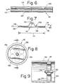
- Each valve unit has a depressible valve member in the form of a ball which, when depressed by the die 62, places the underside of the die 62 in communication with the vacuum drawn in the interior of the die cylinder 22; these valve units 100 will be described in greater detail later with reference to Figs. 10 to 13.
- the valve units are located in rows extending axially along the die cylinder 22, alternate rows 104, 106 being staggered axially with the valve units 100 of the rows 106 being axially halfway between those of the rows 104.
- the rows 104, 106 are spaced apart equally completely around the periphery of the die cylinder 22. There are no valve units in the keyway 50.
- the die cylinder 22 is provided with a plurality of threaded blind bores spaced around and along its curved surface to enable different size dies 62 to be used and accommodate the different positions of the hold-down bolts 90 inserted through the bolt holes 84.
- These threaded bores are preferably provided all over the surface of the die cylinder 22 and in a pattern that will accept the many hold-down bolts of conventional bolted dies, such pattern being indicated in broken lines 107 in Figs. 4 and 5. This then enables the same die cylinder 22 to be used at choice with either vacuum mounted dies 62 or conventional standard bolted dies. This is particularly advantageous if a user needs time to convert standard dies to vacuum mounted dies.
- the ends of the tunnel 116 are not sealed, but are preferably left open as shown in Fig. 7. In this way, air is not trapped and compressed in the tunnel when compressed between the die and the die cylinder; this allows the tunnel to completely and readily collapse.
- the inherent resiliency of the tunnel 116 enables it to return to its raised tunnel shape when the die is removed from the die cylinder.
- Fig. 5 is a similar view to Fig. 4 but additionally shows a second die 138 mounted on the die cylinder 22.
- This second die 138 does not have a key and the die cylinder does not have a second keyway for this die.
- This second die is initially secured to the die cylinder by four corner bolts 140, 142 screwed into the die cylinder 22, two bolts 140 (only one being visible in broken lines) being adjacent the trailing edge of the die 138, and two bolts 142 (only one visible) being adjacent its leading edge.
- the valve units 100 Fig.
- the second die 138 has a peripheral gasket on its underside similar to the peripheral gasket 76 in Fig. 2 of the die 62.
- the trailing edge of the second die 138 abuts and is rearwardly positioned by the leading edge 86 of the keyed die 62.
- a hollow tubular member 154 is telescopically mounted over a guide and support post 156.
- the tubular member 154 has a closed top 158 and a coil spring is compressed between this top 158 and a collar 162 on the post 156.
- the spring 160 is completely enclosed inside the tubular member 154 and urges the top of the member 154 against the ball 150 so resiliently urging the ball 150 against its seat 152.
- the upper surface of the top 158 is formed as a concave cavity 164 to conform to the surface of the ball 150, this facilitating rolling of the ball when contacted by a die.
- the tubular member 154 has radially outwardly extending fins 166 (see Fig.
- the valve is normally closed with the spring 160 resiliently urging the ball 150 against its knife edge seat 152.
- the ball 150 which protrudes proud of the surface of the die cylinder 22
- the ball 150 is moved inwardly into the valve body 144 away from its seat 152.
- this clear and straight-through passage between the tubular member 154 and the valve body 144 offers minimum resistance to air flow, virtually no changes in direction of air flow, and minimizes places in which paper debris, etc. in the air flow could become hung-up and clog the valve unit.
- valve unit In conjunction with the ball member 150 and the knife edge valve seat 152, the valve unit is essentially self-clearing of paper debris etc. In this respect it should also be noted that as the spring 160 is totally enclosed, the spring is not exposed to the air flow through the valve unit and so cannot present any risk of trapping or becoming clogged with paper debris etc.
- the balls 150 can have a diameter in the range 0.125 to 0.5 inches (0.318 to 1.27 cm), preferably less than 0.375 inch (0.952 cm), for example, 0.25 inch (0.635 cm).
- the machine In operation, to mount a die the machine is stopped, that is, the main drive motor 36 and the vacuum blower 46 are stopped.
- the selected die 62 is manually picked-up via the handle cutouts 72 and placed on the die cylinder 22 with the key 68 engaging in the keyway 50 as previously discussed.
- the die 62 is then slid axially along the die cylinder until the bolt holes 84 are aligned with corresponding screw threaded bores in the die cylinder and the reflector 94 on the die 62 is in the central plane 54 in alignment with the sensor unit 58.
Landscapes
- Life Sciences & Earth Sciences (AREA)
- Forests & Forestry (AREA)
- Engineering & Computer Science (AREA)
- Mechanical Engineering (AREA)
- Making Paper Articles (AREA)
- Perforating, Stamping-Out Or Severing By Means Other Than Cutting (AREA)
- Moulds For Moulding Plastics Or The Like (AREA)
Applications Claiming Priority (2)
| Application Number | Priority Date | Filing Date | Title |
|---|---|---|---|
| US194743 | 1988-05-17 | ||
| US07/194,743 US4878407A (en) | 1986-05-01 | 1988-05-17 | Vacuum die mount |
Publications (2)
| Publication Number | Publication Date |
|---|---|
| EP0342776A1 true EP0342776A1 (de) | 1989-11-23 |
| EP0342776B1 EP0342776B1 (de) | 1992-11-25 |
Family
ID=22718750
Family Applications (1)
| Application Number | Title | Priority Date | Filing Date |
|---|---|---|---|
| EP89302153A Expired - Lifetime EP0342776B1 (de) | 1988-05-17 | 1989-03-03 | Vakuum-Matritzenbefestigung |
Country Status (4)
| Country | Link |
|---|---|
| US (1) | US4878407A (de) |
| EP (1) | EP0342776B1 (de) |
| JP (1) | JP2627005B2 (de) |
| DE (1) | DE68903599T2 (de) |
Cited By (1)
| Publication number | Priority date | Publication date | Assignee | Title |
|---|---|---|---|---|
| DE4000078A1 (de) * | 1990-01-03 | 1991-07-04 | Winkler Duennebier Kg Masch | Messerwalze |
Families Citing this family (43)
| Publication number | Priority date | Publication date | Assignee | Title |
|---|---|---|---|---|
| US5035325A (en) * | 1989-07-18 | 1991-07-30 | Dai Nippon Insatsu Kabushiki Kaisha | Cassette for thermal transfer printing film |
| DE3926963C1 (de) * | 1989-08-16 | 1990-12-20 | J.M. Voith Gmbh, 7920 Heidenheim, De | |
| CH682314A5 (de) * | 1989-10-12 | 1993-08-31 | Bobst Sa | |
| US5230271A (en) * | 1990-02-28 | 1993-07-27 | Scm Container Machinery Limited | Rotary die cutting apparatus |
| US5088367A (en) * | 1990-07-30 | 1992-02-18 | Zerand-Bernal Group, Inc. | Rotary die with adjustable blade segment |
| USRE38033E1 (en) | 1993-12-22 | 2003-03-18 | Best Cutting Die Company | Panel cutting apparatus |
| WO1995017286A1 (en) * | 1993-12-22 | 1995-06-29 | Best Cutting Die Company | Panel cutting apparatus |
| US5570620A (en) * | 1993-12-22 | 1996-11-05 | Best Cutting Die Company | Panel cutting apparatus |
| US6532854B2 (en) | 1994-01-21 | 2003-03-18 | Best Cutting Die Company | Cutting die clamping mechanism |
| US5505109A (en) * | 1994-04-26 | 1996-04-09 | Best Cutting Die Company | Cutting die and chisel |
| US5595093A (en) * | 1994-05-12 | 1997-01-21 | Western Printing Machinery Company | Method of forming a rotary cutting die |
| US5697277A (en) * | 1994-05-17 | 1997-12-16 | Best Cutting Die Company | Multi use rotary die plate system |
| US5520080A (en) * | 1994-05-23 | 1996-05-28 | Die-X Ltd. | Die registration and mounting system |
| JP3350258B2 (ja) * | 1994-11-28 | 2002-11-25 | 理想科学工業株式会社 | 排版装置 |
| US6026725A (en) * | 1995-04-10 | 2000-02-22 | Best Cutting Die Company | Panel cutting apparatus with waste repellant die structure |
| JP2952752B2 (ja) * | 1995-11-17 | 1999-09-27 | 株式会社東京機械製作所 | 刷版の版胴への固定および版胴からの解離装置 |
| US6142046A (en) * | 1996-08-06 | 2000-11-07 | Cae Machinery Ltd. | Knife projection sensing system |
| US6076444A (en) * | 1997-08-01 | 2000-06-20 | Best Cutting Die Company | Panel cutting apparatus with selectable matrices for vacuum and air |
| US6059705A (en) * | 1997-10-17 | 2000-05-09 | United Container Machinery, Inc. | Method and apparatus for registering processing heads |
| ES2155334B1 (es) * | 1998-06-01 | 2002-02-01 | Com Ind Maquinaria Carton Ondu | Sistema para la sujecion de troqueles rotativos en maquinas troqueladoras de material laminar. |
| DE19925612B4 (de) * | 1999-06-04 | 2007-10-31 | WINKLER + DüNNEBIER AG | Drehbare Messerwalze mit Folienmesser |
| US6658978B1 (en) * | 1999-10-15 | 2003-12-09 | Ontario Die International Inc. | Steel rule die with removable cutting units |
| DE10040683C2 (de) * | 2000-08-19 | 2002-06-27 | Hinderer & Muehlich Kg | Verfahren zum Positionieren einer Patrize an einer Gegendruckwalze einer Prägestation |
| WO2002072340A2 (en) * | 2001-03-09 | 2002-09-19 | Paper Converting Machine Company | Embossing roll with removable plates |
| US6716017B2 (en) | 2001-03-09 | 2004-04-06 | Paper Converting Machine Company | Embossing roll with removable plates |
| US6925923B2 (en) * | 2001-10-05 | 2005-08-09 | Hycorr Machine Corporation | Rotary cutting die mounting system |
| DK174943B1 (da) * | 2002-02-13 | 2004-03-15 | Inter Ikea Sys Bv | Maskine til udstansning af emner fra en bane af bølgepap samt til dannelse af bukkeanvisningslinier i emnerne |
| US6715394B2 (en) * | 2002-05-07 | 2004-04-06 | W+D Machinery Co., Inc. | Rotatable die |
| US20050040577A1 (en) * | 2003-08-19 | 2005-02-24 | Usun Technology Co., Ltd. | Method writing data to a large block of a flash memory cell |
| CA2458309A1 (en) * | 2003-12-01 | 2005-06-01 | Ontario Die International Inc. | Punch for a braced die |
| US7030365B2 (en) * | 2004-04-15 | 2006-04-18 | Eaton Corporation | Emitter-detector assembly for a reflex photoelectric object detection system |
| GB2413530A (en) | 2004-04-29 | 2005-11-02 | Goss Graphic Systems Ltd | Printing plate module and printing press |
| GB2425987A (en) * | 2005-05-09 | 2006-11-15 | Goss Graphic Systems Ltd | Printing plate unloading apparatus and method |
| GB2428634B (en) * | 2005-08-04 | 2008-09-17 | Goss Graphic Systems Ltd | Printing press |
| KR101319273B1 (ko) * | 2005-12-29 | 2013-10-16 | 엘지디스플레이 주식회사 | 인쇄판 스테이지, 인쇄시스템 및 그를 이용한 액정표시소자제조방법 |
| US8998892B2 (en) | 2007-12-21 | 2015-04-07 | Atricure, Inc. | Ablation device with cooled electrodes and methods of use |
| US8353907B2 (en) | 2007-12-21 | 2013-01-15 | Atricure, Inc. | Ablation device with internally cooled electrodes |
| JP2015020237A (ja) * | 2013-07-18 | 2015-02-02 | 株式会社ディスコ | 切削装置 |
| JP6069122B2 (ja) | 2013-07-22 | 2017-02-01 | 株式会社ディスコ | 切削装置 |
| EP3186045B1 (de) | 2014-08-28 | 2022-03-02 | Dicar Inc. | Ambossabdeckungsinstallation |
| DE102017213389B4 (de) * | 2017-08-02 | 2022-07-28 | Heidelberger Druckmaschinen Ag | Rotationsstanze zum Ausstanzen eines Materialstücks aus einem Bedruckstoff |
| DE102018102638A1 (de) * | 2018-02-06 | 2019-08-08 | Hinderer + Mühlich Gmbh & Co. Kg | Verfahren sowie Vorrichtung zum rotativen Blindprägen eines Substrats, eine Matrize und/oder Patrize zur Verwendung in einer Vorrichtung sowie ein Verfahren zur Herstellung einer Matrize und/oder Patrize |
| ES1285312Y (es) * | 2021-12-23 | 2022-04-19 | Comercial Industrial Maqu Carton Ondulado S L | Cilindro porta-troquel para una máquina troqueladora de material laminar |
Citations (2)
| Publication number | Priority date | Publication date | Assignee | Title |
|---|---|---|---|---|
| US4683822A (en) * | 1985-09-17 | 1987-08-04 | The Ward Machinery Company | Die mounting apparatus |
| DE3711824A1 (de) * | 1986-04-18 | 1987-10-22 | Koyo Jidoki | Verfahren zum ausstanzen und zufuehren von aufklebern nicht rechteckiger form |
Family Cites Families (36)
| Publication number | Priority date | Publication date | Assignee | Title |
|---|---|---|---|---|
| US2033205A (en) * | 1934-07-18 | 1936-03-10 | Equitable Paper Bag Co | Printing cylinder |
| US2060082A (en) * | 1935-03-13 | 1936-11-10 | Pflanze | Means for attaching printing plates to presses |
| US2198765A (en) * | 1938-08-05 | 1940-04-30 | Merritt Engineering & Sales Co | Vacuum cup and vacuum cup system |
| US2680994A (en) * | 1951-10-22 | 1954-06-15 | Boeing Co | Suction holding device |
| US2727463A (en) * | 1952-01-21 | 1955-12-20 | Tingue Brown & Co | Blanketing of printing press impression cylinders |
| US2923235A (en) * | 1958-04-21 | 1960-02-02 | Buser Ag Maschf Fritz | Printing table with movable feed carriage on multi-color printing machines |
| US3110107A (en) * | 1960-05-04 | 1963-11-12 | Wilhelm Charles | Rotatable cylinder |
| US3078796A (en) * | 1961-02-06 | 1963-02-26 | Kamata Hiroyuki | Vacuum clamping of plates for a rotary press |
| CH372546A (fr) * | 1962-01-11 | 1963-10-15 | Bobst Fils Sa J | Procédé de fixation auxiliaire de l'outil d'une presse à platines en position de travail contre le sommier supérieur et dispositif pour la mise en oeuvre de ce procédé |
| US3294392A (en) * | 1963-05-31 | 1966-12-27 | Dunham Tool Company Inc | Vacuum chucking |
| US3295443A (en) * | 1964-06-23 | 1967-01-03 | Matthews & Co Jas H | Printing plate for rotary printing drums and attachment means therefor |
| US3393589A (en) * | 1966-04-15 | 1968-07-23 | William D. Mills | Stock measuring device for controlling stoppage of press |
| US3490369A (en) * | 1966-06-03 | 1970-01-20 | William F Huck | Printing cylinder with plate securing means |
| US3670646A (en) * | 1970-10-09 | 1972-06-20 | Grace W R & Co | Magnetically securable printing plate |
| DE2241703A1 (de) * | 1972-08-24 | 1974-02-28 | Juergen Schulz | Verfahren und vorrichtung zum aufspannen von druckformen auf ihrem traeger |
| US4074595A (en) * | 1972-12-26 | 1978-02-21 | Centenary Central, Inc. | Means for producing die board and cutting rules for same |
| US3907268A (en) * | 1974-03-29 | 1975-09-23 | Thomas F Hale | Valve means for vacuum holding device |
| US4005653A (en) * | 1974-09-09 | 1977-02-01 | Livermore And Knight Co., Inc. | Vacuum cylinder for printing presses |
| JPS5163708A (de) * | 1974-09-26 | 1976-06-02 | Emu Ei Batsukuree Engureibingu | |
| US4056057A (en) * | 1976-02-27 | 1977-11-01 | Livermore And Knight Co., Inc. | Vacuum printing cylinder construction |
| JPS55121647A (en) * | 1979-03-13 | 1980-09-18 | Toshiba Corp | Support for semiconductor device |
| US4237466A (en) * | 1979-05-07 | 1980-12-02 | The Mead Corporation | Paper transport system for an ink jet printer |
| US4361063A (en) * | 1979-05-09 | 1982-11-30 | Bethlehem Steel Corporation | Adaptive control for a dividing shear |
| JPS5646529A (en) * | 1979-09-21 | 1981-04-27 | Citizen Watch Co Ltd | Wafer chuck |
| DK155169C (da) * | 1980-04-16 | 1989-07-03 | Eskofot As | Sugekassette |
| DE3140882A1 (de) * | 1980-10-17 | 1982-05-27 | Dai Nippon Insatsu K.K., Tokyo | Vorrichtung zum befestigen einer offset-druckplatte oder einer aehnlichen platte in ebenem zustand durch unterdruck |
| JPS57132938A (en) * | 1981-02-09 | 1982-08-17 | Nec Corp | Vacuum adsorbing device |
| GB2099750B (en) * | 1981-06-06 | 1985-06-26 | Samco Strong Ltd | Stroke control for press |
| DE3136701C1 (de) * | 1981-09-16 | 1983-04-07 | M.A.N.- Roland Druckmaschinen AG, 6050 Offenbach | Vorrichtung zum Abtasten von auf Druckgut aufgedruckten,die Lagegenauigkeit des Druckfarbenauftrages charakterisierender Passmarken |
| FR2527520A1 (fr) * | 1982-05-27 | 1983-12-02 | Cuir Jean Pierre | Dispositif de fixation d'une plaque sur un cylindre |
| US4471802A (en) * | 1983-04-12 | 1984-09-18 | Victor Equipment Company, Inc. | Pressure regulator assembly with improved cartridge |
| DE8317151U1 (de) * | 1983-06-11 | 1983-11-24 | Hanauer Stempelfabrik Schwachhöfer & Opstelten, 6450 Hanau | Halterung fuer eine druckplatte |
| DE3339552A1 (de) * | 1983-11-02 | 1985-05-09 | M.A.N.- Roland Druckmaschinen AG, 6050 Offenbach | Voreinstellen an druckmaschinen |
| US4589338A (en) * | 1984-02-17 | 1986-05-20 | Billy Collins | Flexographic plate mounting apparatus and method |
| US4641577A (en) * | 1985-04-12 | 1987-02-10 | Sweeny Peter K | Apparatus for adjusting the plate segment of an off-set lithographic printer |
| US4744297A (en) * | 1985-09-17 | 1988-05-17 | The Ward Machinery Company | Mounting printing plates |
-
1988
- 1988-05-17 US US07/194,743 patent/US4878407A/en not_active Expired - Lifetime
-
1989
- 1989-03-03 DE DE8989302153T patent/DE68903599T2/de not_active Expired - Fee Related
- 1989-03-03 EP EP89302153A patent/EP0342776B1/de not_active Expired - Lifetime
- 1989-03-16 JP JP1062367A patent/JP2627005B2/ja not_active Expired - Lifetime
Patent Citations (2)
| Publication number | Priority date | Publication date | Assignee | Title |
|---|---|---|---|---|
| US4683822A (en) * | 1985-09-17 | 1987-08-04 | The Ward Machinery Company | Die mounting apparatus |
| DE3711824A1 (de) * | 1986-04-18 | 1987-10-22 | Koyo Jidoki | Verfahren zum ausstanzen und zufuehren von aufklebern nicht rechteckiger form |
Cited By (2)
| Publication number | Priority date | Publication date | Assignee | Title |
|---|---|---|---|---|
| DE4000078A1 (de) * | 1990-01-03 | 1991-07-04 | Winkler Duennebier Kg Masch | Messerwalze |
| US5109741A (en) * | 1990-01-03 | 1992-05-05 | Winkler & Duennebier Maschinenfabrik Und Eisengiesserei Kg | Knife roller |
Also Published As
| Publication number | Publication date |
|---|---|
| JPH0238031A (ja) | 1990-02-07 |
| DE68903599D1 (de) | 1993-01-07 |
| US4878407A (en) | 1989-11-07 |
| DE68903599T2 (de) | 1993-05-19 |
| JP2627005B2 (ja) | 1997-07-02 |
| EP0342776B1 (de) | 1992-11-25 |
Similar Documents
| Publication | Publication Date | Title |
|---|---|---|
| US4878407A (en) | Vacuum die mount | |
| CA1163182A (en) | Stripping device for removing waste sheet board | |
| US5701789A (en) | Waste repellent die structure | |
| EP0692347B1 (de) | Verfahren und Vorrichtung zur Herstellung von kernlosen Papierrollen | |
| CA1176094A (en) | Method for producing plastic-coated containers for liquids | |
| CA2211045A1 (en) | System and method of dispensing coreless rolls of paper products | |
| EP0791539B1 (de) | Verfahren und Vorrichtung zum Herstellen von Klappschachteln für Zigaretten | |
| EP0215645A2 (de) | Montieren von Matrizen und Druckplatten | |
| US4604154A (en) | Apparatus and method for guiding plastic labels to a label-wrapping station | |
| CA2128640A1 (en) | Differential speed lay-on rolls in a web winding system | |
| US4759249A (en) | Web slitting apparatus having adjustable lower cutting blades | |
| EP0739730B1 (de) | Flexographische Druckmaschine | |
| US4799414A (en) | Rotary cutter apparatus | |
| JPH0524344U (ja) | 段ボールシート用切断装置 | |
| EP1202854B1 (de) | Verfahren und werkzeug zum stanzen von verpackungsmaterial und deren verwendung | |
| NO309130B1 (no) | Fremgangsmåte for reparering av en lokalt skadet, inntrykt overflate av en vegg så vel som en vegg innbefattende en slik lokalt reparert overflate | |
| CA1125163A (en) | Method and apparatus for cutting plastic film windows for cartons | |
| EP4422836A1 (de) | Anordnung für eine wellpappeanlage | |
| US5009736A (en) | Method of and an arrangement for gluing a web to a core in a reeling device | |
| EP1669142B1 (de) | Verfahren zum Prägen eines Behälterkörpers an einer genauen Position | |
| US5334129A (en) | Cross-cutter for final treatment or finishing of webs of material | |
| CA2063231A1 (en) | Manually-fed machine for the formation of tabs on sheet stock | |
| CA2141891A1 (en) | Tearing-off roller pair | |
| EP0695689B1 (de) | Verfahren und Vorrichtung zum Verpacken einer Rolle aus einer aufgewickelten Materialbahn | |
| JP2604785Y2 (ja) | ロータリダイカッタのストリップ除去装置 |
Legal Events
| Date | Code | Title | Description |
|---|---|---|---|
| PUAI | Public reference made under article 153(3) epc to a published international application that has entered the european phase |
Free format text: ORIGINAL CODE: 0009012 |
|
| AK | Designated contracting states |
Kind code of ref document: A1 Designated state(s): CH DE FR GB IT LI SE |
|
| 17P | Request for examination filed |
Effective date: 19900321 |
|
| 17Q | First examination report despatched |
Effective date: 19910628 |
|
| GRAA | (expected) grant |
Free format text: ORIGINAL CODE: 0009210 |
|
| AK | Designated contracting states |
Kind code of ref document: B1 Designated state(s): CH DE FR GB IT LI SE |
|
| ITF | It: translation for a ep patent filed | ||
| REF | Corresponds to: |
Ref document number: 68903599 Country of ref document: DE Date of ref document: 19930107 |
|
| ET | Fr: translation filed | ||
| PGFP | Annual fee paid to national office [announced via postgrant information from national office to epo] |
Ref country code: SE Payment date: 19930215 Year of fee payment: 5 |
|
| PLBE | No opposition filed within time limit |
Free format text: ORIGINAL CODE: 0009261 |
|
| STAA | Information on the status of an ep patent application or granted ep patent |
Free format text: STATUS: NO OPPOSITION FILED WITHIN TIME LIMIT |
|
| 26N | No opposition filed | ||
| PG25 | Lapsed in a contracting state [announced via postgrant information from national office to epo] |
Ref country code: SE Free format text: LAPSE BECAUSE OF NON-PAYMENT OF DUE FEES Effective date: 19940304 |
|
| EUG | Se: european patent has lapsed |
Ref document number: 89302153.5 Effective date: 19941010 |
|
| REG | Reference to a national code |
Ref country code: GB Ref legal event code: IF02 |
|
| PGFP | Annual fee paid to national office [announced via postgrant information from national office to epo] |
Ref country code: FR Payment date: 20020221 Year of fee payment: 14 |
|
| PGFP | Annual fee paid to national office [announced via postgrant information from national office to epo] |
Ref country code: CH Payment date: 20020225 Year of fee payment: 14 |
|
| PGFP | Annual fee paid to national office [announced via postgrant information from national office to epo] |
Ref country code: GB Payment date: 20020227 Year of fee payment: 14 |
|
| PGFP | Annual fee paid to national office [announced via postgrant information from national office to epo] |
Ref country code: DE Payment date: 20020320 Year of fee payment: 14 |
|
| PG25 | Lapsed in a contracting state [announced via postgrant information from national office to epo] |
Ref country code: GB Free format text: LAPSE BECAUSE OF NON-PAYMENT OF DUE FEES Effective date: 20030303 |
|
| PG25 | Lapsed in a contracting state [announced via postgrant information from national office to epo] |
Ref country code: LI Free format text: LAPSE BECAUSE OF NON-PAYMENT OF DUE FEES Effective date: 20030331 Ref country code: CH Free format text: LAPSE BECAUSE OF NON-PAYMENT OF DUE FEES Effective date: 20030331 |
|
| PG25 | Lapsed in a contracting state [announced via postgrant information from national office to epo] |
Ref country code: DE Free format text: LAPSE BECAUSE OF NON-PAYMENT OF DUE FEES Effective date: 20031001 |
|
| GBPC | Gb: european patent ceased through non-payment of renewal fee | ||
| REG | Reference to a national code |
Ref country code: CH Ref legal event code: PL |
|
| PG25 | Lapsed in a contracting state [announced via postgrant information from national office to epo] |
Ref country code: FR Free format text: LAPSE BECAUSE OF NON-PAYMENT OF DUE FEES Effective date: 20031127 |
|
| REG | Reference to a national code |
Ref country code: FR Ref legal event code: ST |
|
| PG25 | Lapsed in a contracting state [announced via postgrant information from national office to epo] |
Ref country code: IT Free format text: LAPSE BECAUSE OF NON-PAYMENT OF DUE FEES;WARNING: LAPSES OF ITALIAN PATENTS WITH EFFECTIVE DATE BEFORE 2007 MAY HAVE OCCURRED AT ANY TIME BEFORE 2007. THE CORRECT EFFECTIVE DATE MAY BE DIFFERENT FROM THE ONE RECORDED. Effective date: 20050303 |