EP0342406B1 - Blindeinnietmutter - Google Patents
Blindeinnietmutter Download PDFInfo
- Publication number
- EP0342406B1 EP0342406B1 EP89107661A EP89107661A EP0342406B1 EP 0342406 B1 EP0342406 B1 EP 0342406B1 EP 89107661 A EP89107661 A EP 89107661A EP 89107661 A EP89107661 A EP 89107661A EP 0342406 B1 EP0342406 B1 EP 0342406B1
- Authority
- EP
- European Patent Office
- Prior art keywords
- nut according
- closure element
- blind rivet
- closure
- hollow stem
- Prior art date
- Legal status (The legal status is an assumption and is not a legal conclusion. Google has not performed a legal analysis and makes no representation as to the accuracy of the status listed.)
- Expired - Lifetime
Links
Images
Classifications
-
- F—MECHANICAL ENGINEERING; LIGHTING; HEATING; WEAPONS; BLASTING
- F16—ENGINEERING ELEMENTS AND UNITS; GENERAL MEASURES FOR PRODUCING AND MAINTAINING EFFECTIVE FUNCTIONING OF MACHINES OR INSTALLATIONS; THERMAL INSULATION IN GENERAL
- F16B—DEVICES FOR FASTENING OR SECURING CONSTRUCTIONAL ELEMENTS OR MACHINE PARTS TOGETHER, e.g. NAILS, BOLTS, CIRCLIPS, CLAMPS, CLIPS OR WEDGES; JOINTS OR JOINTING
- F16B19/00—Bolts without screw-thread; Pins, including deformable elements; Rivets
- F16B19/04—Rivets; Spigots or the like fastened by riveting
- F16B19/08—Hollow rivets; Multi-part rivets
- F16B19/10—Hollow rivets; Multi-part rivets fastened by expanding mechanically
- F16B19/1027—Multi-part rivets
- F16B19/1036—Blind rivets
- F16B19/1045—Blind rivets fastened by a pull - mandrel or the like
-
- F—MECHANICAL ENGINEERING; LIGHTING; HEATING; WEAPONS; BLASTING
- F16—ENGINEERING ELEMENTS AND UNITS; GENERAL MEASURES FOR PRODUCING AND MAINTAINING EFFECTIVE FUNCTIONING OF MACHINES OR INSTALLATIONS; THERMAL INSULATION IN GENERAL
- F16B—DEVICES FOR FASTENING OR SECURING CONSTRUCTIONAL ELEMENTS OR MACHINE PARTS TOGETHER, e.g. NAILS, BOLTS, CIRCLIPS, CLAMPS, CLIPS OR WEDGES; JOINTS OR JOINTING
- F16B37/00—Nuts or like thread-engaging members
- F16B37/04—Devices for fastening nuts to surfaces, e.g. sheets, plates
- F16B37/06—Devices for fastening nuts to surfaces, e.g. sheets, plates by means of welding or riveting
- F16B37/062—Devices for fastening nuts to surfaces, e.g. sheets, plates by means of welding or riveting by means of riveting
- F16B37/065—Devices for fastening nuts to surfaces, e.g. sheets, plates by means of welding or riveting by means of riveting by deforming the material of the nut
Definitions
- the invention relates to a blind rivet nut with a hollow shaft which is provided on the side facing away from the setting head with an internal thread for the mandrel of a blind rivet setting tool.
- blind rivet nuts of this type are produced with an open or closed shaft end.
- a closed version of a blind rivet nut is much more expensive, because in addition to the more expensive blind hole thread, the version must also have a longer length, which is due to the fact that, in addition to the required floor, space for the drill tip, the cut, and a certain level of production safety must be provided . If longer set screws are screwed into the shaft thread, the required length can increase further.
- the closed shaft end cannot be dispensed with if, for example, the inner part of the workpiece is foamed over fire-proof doors, refrigerators or the like. If the end of the shaft is not closed, foreign substances get into the thread when the workpiece is foamed.
- the invention is therefore based on the object of making an inexpensive, simplified blind rivet nut available which can be produced in a less complex and inexpensive manner and which can be used in cases where expensive blind rivet nuts with a closed design are used and open blind rivet nuts are used forbids.
- the invention consists in that in a blind rivet nut of the type mentioned at the beginning of the hollow shaft at the end opposite the setting head, with one its closing position removable closure element is provided.
- the closure element consists of a closure body clamped in the hollow shaft end.
- the closure element advantageously closes the hollow shaft in an airtight manner with respect to the internal thread.
- closure body consists of a ball.
- the invention proposes that the closure body sits in a thread-free bore at the end of the hollow shaft.
- the closure element can also consist of a thin, deformable or penetrable closure body in the case of a thin sheet metal or a plastic film.
- the closure element consists of a threaded part that can be unscrewed.
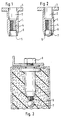
- a blind rivet nut 1 is shown, which is penetrated centrally by a hollow shaft 2.
- the hollow shaft 2 opposite the setting head 3 On the side of the hollow shaft 2 opposite the setting head 3, the latter is provided with an internal thread 4, into which the mandrel of a tool, not shown, can be screwed.
- the end of the hollow shaft 2 opposite the setting head 3 has a thread-free bore 6.
- a closure body in the form of a ball 7 is pressed into the thread-free bore 6.
- a screw 8 introduced after the foaming has hardened pushes out the closure body 7 with its front threaded part 9, as is shown in detail in FIG. 3. In this way, it is possible to process screws 8 with any screw length without the blind rivet nut 1 having to be made correspondingly long.
- the closure body 7 can also have a different shape, and the thread-free recess 6 at the end 5 of the shaft 2 can also be configured accordingly.
- a thin, deformable or pierceable closure body as the closure element instead of a ball 7, for example in the form of a thin sheet or a plastic film which can then be pierced by the front threaded part 9 of a screw 8.
- closure element consists of a threaded part which can be moved out by a correspondingly inserted screw 8.
- the invention makes available a blind rivet nut which has the advantages of an open embodiment and permits use in applications in which only blind rivet nuts with a closed shaft can be used.
Landscapes
- Engineering & Computer Science (AREA)
- General Engineering & Computer Science (AREA)
- Mechanical Engineering (AREA)
- Insertion Pins And Rivets (AREA)
Description
- Die Erfindung betrifft eine Blindeinnietmutter mit einem Hohlschaft, der auf der vom Setzkopf abgewandten Seite mit einem Innengewinde für den Zugdorn eines Blindnietsetzwerkzeuges versehen ist.
- Derartige Blindeinnietmuttern werden mit einem offenen oder geschlossenen Schaftende hergestellt. Eine geschlossene Ausführung einer Blindeinnietmutter ist wesentlich teurer, da neben dem teureren Sackloch-Gewinde die Ausführung auch eine größere Länge aufweisen muß, die dadurch bedingt ist, daß neben dem erforderlichen Boden, Raum für die Bohrerspitze, den Anschnitt, sowie eine gewisse Produktionssicherheit vorzusehen ist. Werden längere Stellschrauben in das Schaftgewinde eingeschraubt, kann sich die erforderliche Länge weiter erhöhen. Andererseits kann auf das geschlossene Schaftende nicht verzichtet werden, wenn beispielsweise das Innenteil des Werkstückes ausgeschäumt wird über feuerfesten Türen, Kühlschränken oder dergleichen. Ist das Schaftende nicht verschlossen, so gelangen beim Ausschäumen des Werkstückes Fremdstoffe in das Gewinde.
- Der Erfindung liegt daher die Aufgabe zugrunde, eine kostengünstige, vereinfachte Blindnietmutter verfügbar zu machen, die in wenig aufwendiger und kostengünstiger Weise hergestellt werden kann und einen Einsatz in den Fällen ermöglicht, wo teure Blindeinnietmuttern mit geschlossener Ausführung zur Anwendung kommen und sich der Einsatz offener Blindeinnietmuttern verbietet.
- Die Erfindung besteht darin, daß bei einer Blindeinnietmutter der eingangs erwähnten Art der Hohlschaft an dem Ende, das dem Setzkopf gegenüberliegt, mit einem aus seiner verschließenden Lage entfernbaren Verschlußelement versehen ist.
- In einer zweckmäßigen Ausführungsform besteht das Verschlußelement aus einem in das Hohlschaftende eingeklemmten Verschlußkörper.
- In vorteilhafter Weise schließt das Verschlußelement den Hohlschaft gegenüber dem Innengewinde luftdicht ab.
- Eine vorteilhafte Ausführungsform der Erfindung besteht darin, daß der Verschlußkörper aus einer Kugel besteht.
- In einer Weiterbildung schlägt die Erfindung vor, daß der Verschlußkörper in einer gewindefreien Aufbohrung am Hohlschaftende sitzt.
- Das Verschlußelement kann auch aus einem dünnen, verformbaren oder durchstoßbaren Verschlußkörper bei einem dünnen Blech oder einer Kunststoff-Folie bestehen.
- In einer Abwandlung kann vorgesehen sein, daß das Verschlußelement aus einem herausschraubbaren Gewindeteil besteht.
- Die Erfindung soll nachstehend anhand eines Ausführungsbeispieles unter Bezugnahme auf die beigefügten Zeichnungen näher erläutert werden.
- In den Zeichnungen zeigen:
- Fig. 1
- eine erfindungsgemäße Blindeinnietmutter,
- Fig. 2
- eine Blindeinnietmutter nach Fig. 1 mit einem eingesetzten Verschlußkörper und
- Fig. 3
- eine Ausführungsform der erfindungsgemäßen Blindeinnietmutter im eingebauten Zustand mit herausbewegtem Verschlußkörper.
- In Fig. 1 ist eine Blindeinnietmutter 1 dargestellt, die mittig von einem Hohlschaft 2 durchzogen wird. An der dem Setzkopf 3 gegenüberliegenden Seite des Hohlschaftes 2 ist dieser mit einem Innengewinde 4 versehen, in das der Zugdorn eines nicht dargestellten Werkzeugs eingeschraubt werden kann. Das dem Setzkopf 3 gegenüberliegende Ende des Hohlschaftes 2 weist eine gewindefreie Aufbohrung 6 auf.
- Wie Fig. 2 zeigt, ist in die gewindefreie Aufbohrung 6 ein Verschlußkörper in Form einer Kugel 7 eingepreßt.
- Wird eine derartige Blindeinnietmutter gesetzt und das Werkstück nachfolgend ausgeschäumt, wie es Fig. 3 darstellt, so können Fremdstoffe nicht in das Gewinde gelangen. Eine nach dem Aushärten der Verschäumung eingeführte Schraube 8 stößt mit ihrem vorderen Gewindeteil 9 den Verschlußkörper 7 heraus, wie es im einzelnen in Fig. 3 dargestellt ist. Auf diese Weise ist es möglich, Schrauben 8 mit beliebiger Schraubenlänge zu verarbeiten, ohne daß die Blindeinnietmutter 1 entsprechend lang ausgestaltet werden muß. Der Verschlußkörper 7 kann auch eine andere Gestalt aufweisen, und in entsprechender Anpassung kann auch die gewindefreie Ausnehmung 6 am Ende 5 des Schaftes 2 ausgestaltet sein.
- Auch ist es möglich, als Verschlußelement statt einer Kugel 7 einen dünnen, verformbaren oder durchstoßbaren Verschlußkörper zu verwenden, beispielsweise in Form eines dünnen Bleches oder einer Kunststoff-Folie, die dann von dem vorderen Gewindeteil 9 einer Schraube 8 durchstoßen werden kann.
- Es ist auch denkbar, daß das Verschlußelement aus einem Gewindeteil besteht, das von einer entsprechend eingeführten Schraube 8 herausbewegbar ist.
- Die Erfindung macht in jedem Fall eine Blindeinnietmutter verfügbar, die die Vorteile einer offenen Ausführungsform besitzt und den Einsatz in Anwendungsfällen erlaubt, bei denen nur Blindeinnietmuttern mit geschlossenem Schaft zur Anwendung kommen können.
Claims (9)
Applications Claiming Priority (2)
| Application Number | Priority Date | Filing Date | Title |
|---|---|---|---|
| DE8806441U | 1988-05-17 | ||
| DE8806441U DE8806441U1 (de) | 1988-05-17 | 1988-05-17 | Blindeinnietmutter |
Publications (2)
| Publication Number | Publication Date |
|---|---|
| EP0342406A1 EP0342406A1 (de) | 1989-11-23 |
| EP0342406B1 true EP0342406B1 (de) | 1991-07-10 |
Family
ID=6824103
Family Applications (1)
| Application Number | Title | Priority Date | Filing Date |
|---|---|---|---|
| EP89107661A Expired - Lifetime EP0342406B1 (de) | 1988-05-17 | 1989-04-27 | Blindeinnietmutter |
Country Status (2)
| Country | Link |
|---|---|
| EP (1) | EP0342406B1 (de) |
| DE (2) | DE8806441U1 (de) |
Families Citing this family (3)
| Publication number | Priority date | Publication date | Assignee | Title |
|---|---|---|---|---|
| FR2642802B1 (fr) * | 1989-02-08 | 1991-06-07 | Rapid Sa | Ecrou a montage en aveugle et par sertissage sur une paroi quelconque |
| IT245299Y1 (it) | 1998-03-02 | 2002-03-20 | Electrolux Zanussi Elettrodome | Macchina perfezionata per lavare e/o asciugare biancheria |
| DE102005025276A1 (de) * | 2005-01-13 | 2006-07-20 | Fischerwerke Artur Fischer Gmbh & Co. Kg | Befestigung in einer Platte |
Family Cites Families (2)
| Publication number | Priority date | Publication date | Assignee | Title |
|---|---|---|---|---|
| DE3035867A1 (de) * | 1979-09-28 | 1981-04-16 | Aerpat Ag, Zug | Selbstverstopfender blindniet |
| GB8517659D0 (en) * | 1985-07-12 | 1985-08-21 | Avdel Ltd | Self-plugging blind fastener |
-
1988
- 1988-05-17 DE DE8806441U patent/DE8806441U1/de not_active Expired
-
1989
- 1989-04-27 DE DE8989107661T patent/DE58900164D1/de not_active Expired - Fee Related
- 1989-04-27 EP EP89107661A patent/EP0342406B1/de not_active Expired - Lifetime
Also Published As
| Publication number | Publication date |
|---|---|
| EP0342406A1 (de) | 1989-11-23 |
| DE8806441U1 (de) | 1988-07-07 |
| DE58900164D1 (de) | 1991-08-14 |
Similar Documents
| Publication | Publication Date | Title |
|---|---|---|
| CH660205A5 (de) | Verstellbares tuer- und fensterband. | |
| DE2345017A1 (de) | Befestigungselement | |
| DE1902813U (de) | Sicherungsschraubenbefestigung. | |
| DE3407033A1 (de) | Schluessel | |
| EP0475097A2 (de) | Durchflussregler | |
| DE19816533A1 (de) | Vorrichtung zur Befestigung von Innenverkleidungen für Fahrzeuge | |
| DE2735660C3 (de) | Befestigungsvorrichtung, insbesondere für eine Bordschalttafel eines Automobils | |
| DE2853976A1 (de) | Selbstfurchende bohrschraube | |
| DE2153062C3 (de) | Einstückiges Befestigungselement aus Kunststoff | |
| DE69001664T2 (de) | Profil fuer tuer, fenster oder paneele. | |
| DE4200096C2 (de) | Vorrichtung zum Verschließen einer Öffnung in einer Verkleidung | |
| EP0342406B1 (de) | Blindeinnietmutter | |
| DE2615322C2 (de) | Befestigungsvorrichtung für Türschilder bzw. Türrosetten | |
| DE69800028T2 (de) | Vorrichtung zum Herstellen durch Stanzen eines kegelstumpförmigen Lochs in einem Metallbandmaterial insbesondere einer Stulpschiene | |
| DE1914990C3 (de) | Befestigungselement | |
| EP1104835B1 (de) | Lochabdichtungsvorrichtung für Durchgangsöffnungen von Mehrscheiben-Isolierglas | |
| CH618238A5 (en) | Fastening kit with an expanding dowel and a fastening screw | |
| EP0466713A1 (de) | Mehrteiliger dübel. | |
| DE2707291B2 (de) | Nieten- oder Schraubenverbindung zweier mittel- oder unmittelbar aneinanderliegender Metallbleche | |
| EP1052748A1 (de) | Bedienungselement zum Befestigen an einer Frontplatte | |
| DE2403974C2 (de) | Befestigungselement | |
| DE951424C (de) | Loesbare Befestigung eines einseitigen Tuergriffs | |
| WO2002027128A9 (de) | Türband | |
| DE2352064C3 (de) | GewindeschloBverbindung | |
| DE2024854A1 (de) | Kunststoffverkleidungsteil für Zylinderkopfschrauben |
Legal Events
| Date | Code | Title | Description |
|---|---|---|---|
| PUAI | Public reference made under article 153(3) epc to a published international application that has entered the european phase |
Free format text: ORIGINAL CODE: 0009012 |
|
| 17P | Request for examination filed |
Effective date: 19890921 |
|
| AK | Designated contracting states |
Kind code of ref document: A1 Designated state(s): DE FR GB IT |
|
| 17Q | First examination report despatched |
Effective date: 19901219 |
|
| ITF | It: translation for a ep patent filed | ||
| GRAA | (expected) grant |
Free format text: ORIGINAL CODE: 0009210 |
|
| AK | Designated contracting states |
Kind code of ref document: B1 Designated state(s): DE FR GB IT |
|
| GBT | Gb: translation of ep patent filed (gb section 77(6)(a)/1977) | ||
| REF | Corresponds to: |
Ref document number: 58900164 Country of ref document: DE Date of ref document: 19910814 |
|
| ET | Fr: translation filed | ||
| PLBE | No opposition filed within time limit |
Free format text: ORIGINAL CODE: 0009261 |
|
| STAA | Information on the status of an ep patent application or granted ep patent |
Free format text: STATUS: NO OPPOSITION FILED WITHIN TIME LIMIT |
|
| 26N | No opposition filed | ||
| REG | Reference to a national code |
Ref country code: GB Ref legal event code: IF02 |
|
| PGFP | Annual fee paid to national office [announced via postgrant information from national office to epo] |
Ref country code: GB Payment date: 20040330 Year of fee payment: 16 |
|
| PGFP | Annual fee paid to national office [announced via postgrant information from national office to epo] |
Ref country code: FR Payment date: 20040421 Year of fee payment: 16 |
|
| PGFP | Annual fee paid to national office [announced via postgrant information from national office to epo] |
Ref country code: DE Payment date: 20040528 Year of fee payment: 16 |
|
| PG25 | Lapsed in a contracting state [announced via postgrant information from national office to epo] |
Ref country code: IT Free format text: LAPSE BECAUSE OF NON-PAYMENT OF DUE FEES;WARNING: LAPSES OF ITALIAN PATENTS WITH EFFECTIVE DATE BEFORE 2007 MAY HAVE OCCURRED AT ANY TIME BEFORE 2007. THE CORRECT EFFECTIVE DATE MAY BE DIFFERENT FROM THE ONE RECORDED. Effective date: 20050427 Ref country code: GB Free format text: LAPSE BECAUSE OF NON-PAYMENT OF DUE FEES Effective date: 20050427 |
|
| PG25 | Lapsed in a contracting state [announced via postgrant information from national office to epo] |
Ref country code: DE Free format text: LAPSE BECAUSE OF NON-PAYMENT OF DUE FEES Effective date: 20051101 |
|
| GBPC | Gb: european patent ceased through non-payment of renewal fee |
Effective date: 20050427 |
|
| PG25 | Lapsed in a contracting state [announced via postgrant information from national office to epo] |
Ref country code: FR Free format text: LAPSE BECAUSE OF NON-PAYMENT OF DUE FEES Effective date: 20051230 |
|
| REG | Reference to a national code |
Ref country code: FR Ref legal event code: ST Effective date: 20051230 |