EP0342347A2 - Méthode pour réduire l'effet de grandeurs déréglantes pour brûleurs à soufflerie et brûleurs à soufflerie - Google Patents
Méthode pour réduire l'effet de grandeurs déréglantes pour brûleurs à soufflerie et brûleurs à soufflerie Download PDFInfo
- Publication number
- EP0342347A2 EP0342347A2 EP89106131A EP89106131A EP0342347A2 EP 0342347 A2 EP0342347 A2 EP 0342347A2 EP 89106131 A EP89106131 A EP 89106131A EP 89106131 A EP89106131 A EP 89106131A EP 0342347 A2 EP0342347 A2 EP 0342347A2
- Authority
- EP
- European Patent Office
- Prior art keywords
- air
- pressure
- change
- gas
- mass flow
- Prior art date
- Legal status (The legal status is an assumption and is not a legal conclusion. Google has not performed a legal analysis and makes no representation as to the accuracy of the status listed.)
- Granted
Links
Images

Classifications
-
- F—MECHANICAL ENGINEERING; LIGHTING; HEATING; WEAPONS; BLASTING
- F23—COMBUSTION APPARATUS; COMBUSTION PROCESSES
- F23N—REGULATING OR CONTROLLING COMBUSTION
- F23N1/00—Regulating fuel supply
- F23N1/02—Regulating fuel supply conjointly with air supply
- F23N1/022—Regulating fuel supply conjointly with air supply using electronic means
-
- F—MECHANICAL ENGINEERING; LIGHTING; HEATING; WEAPONS; BLASTING
- F23—COMBUSTION APPARATUS; COMBUSTION PROCESSES
- F23N—REGULATING OR CONTROLLING COMBUSTION
- F23N2223/00—Signal processing; Details thereof
-
- F—MECHANICAL ENGINEERING; LIGHTING; HEATING; WEAPONS; BLASTING
- F23—COMBUSTION APPARATUS; COMBUSTION PROCESSES
- F23N—REGULATING OR CONTROLLING COMBUSTION
- F23N2223/00—Signal processing; Details thereof
- F23N2223/34—Signal processing; Details thereof with feedforward processing
-
- F—MECHANICAL ENGINEERING; LIGHTING; HEATING; WEAPONS; BLASTING
- F23—COMBUSTION APPARATUS; COMBUSTION PROCESSES
- F23N—REGULATING OR CONTROLLING COMBUSTION
- F23N2225/00—Measuring
- F23N2225/04—Measuring pressure
-
- F—MECHANICAL ENGINEERING; LIGHTING; HEATING; WEAPONS; BLASTING
- F23—COMBUSTION APPARATUS; COMBUSTION PROCESSES
- F23N—REGULATING OR CONTROLLING COMBUSTION
- F23N2225/00—Measuring
- F23N2225/08—Measuring temperature
- F23N2225/13—Measuring temperature outdoor temperature
-
- F—MECHANICAL ENGINEERING; LIGHTING; HEATING; WEAPONS; BLASTING
- F23—COMBUSTION APPARATUS; COMBUSTION PROCESSES
- F23N—REGULATING OR CONTROLLING COMBUSTION
- F23N2225/00—Measuring
- F23N2225/08—Measuring temperature
- F23N2225/21—Measuring temperature outlet temperature
-
- F—MECHANICAL ENGINEERING; LIGHTING; HEATING; WEAPONS; BLASTING
- F23—COMBUSTION APPARATUS; COMBUSTION PROCESSES
- F23N—REGULATING OR CONTROLLING COMBUSTION
- F23N2235/00—Valves, nozzles or pumps
- F23N2235/02—Air or combustion gas valves or dampers
- F23N2235/10—Air or combustion gas valves or dampers power assisted, e.g. using electric motors
-
- F—MECHANICAL ENGINEERING; LIGHTING; HEATING; WEAPONS; BLASTING
- F23—COMBUSTION APPARATUS; COMBUSTION PROCESSES
- F23N—REGULATING OR CONTROLLING COMBUSTION
- F23N2235/00—Valves, nozzles or pumps
- F23N2235/12—Fuel valves
- F23N2235/16—Fuel valves variable flow or proportional valves
Definitions
- the present invention relates to a method for reducing the effect of disturbance variables on the combustion in fan burner systems in which a fuel and / or air flow is set according to a desired load level, a fan burner system with a fan burner with air supply and fuel supply, an arrangement for measuring a relative Change in density or, with at least almost constant gas volume flow, a relative change in mass flow of a gas as a function of its pressure and temperature, and use of the method.
- the procedure according to claim 4 is preferably used.
- a pressure equalization is created between the sample gas and the gas, thus determining the pressure reference size.
- the measured relative end tion of the pressure difference is equal to the relative change in density in the gas and, with at least an almost constant gas volume flow, is at least almost equal to the relative change in gas mass flow.
- a forced draft burner system according to the invention is distinguished by the wording of claim 7, and an arrangement for measuring the relative change in density of a gas as a function of its pressure and its temperature is distinguished by the wording of claim 9.
- the method according to the invention is particularly suitable for use on forced draft burners which are operated in discrete load stages, in particular for one- or two-stage forced draft burners.
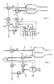
- a burner 1 schematically shows a burner 1 for the combustion of fuel with a practically constant calorific value, such as heating oil EL, natural gas etc.
- the fuel flow B * is fed to the burner 1 via a line 3 with actuator 5 and, analogously, via a line 7 the air flow L *, in turn provided by an actuator 9.
- the two actuators 5 and 9 are driven by servomotors 11 and 13.
- disturbance variables z such as fuel pressure, specific air requirement, air temperature, air pressure, air humidity, conditions on the chimney draft
- a sensor arrangement 17 On the output side of the compensator arrangement 19 shown in FIG. 1, compensation signals s B and s L are generated, which are each fed to a superimposition unit 21 or 23 in the fuel flow and / or air flow control path. The influence of the measured disturbance variables z is thus compensated for by intervention in the fuel flow and / or air flow.
- the relative change in the air mass flow with at least almost constant air volume flow is at least almost equal to the difference between the relative change in air pressure and the relative change in air temperature, both the combustion air supplied to the burner. It can now be shown that the relative change of the air factor is equal to the relative change in the air mass flow mentioned in (1), or that the related change in the oxygen content in the flue gas is, in a first approximation, proportional to the relative change in the air mass flow mentioned.
- the fuel pressure in particular the setpoint of an intended fuel pressure control, is to be intervened, this is done, at least to a first approximation in which means: the change in fuel pressure with respect to the fuel pressure at the above-mentioned reference ratios.
- FIG. 1 schematically shows a fan burner system according to the invention, which has a compensation arrangement, in order to compensate for the influence of the main disturbance variables mentioned.
- the air temperature ⁇ L and the static air pressure p L are measured in the air flow L * of the burner, which is basically constructed and fed as shown in FIG. 1.
- the compensator 25 which acts as a superimposition unit according to (1), is supplied with adjustable constants K p and K ⁇ in accordance with the standardization variables and from (1).
- the pressure measured value signal is first weighted at the compensator 25 with the normalization factor K p and analogously the temperature measured value signal with the weighting factor K regimen. By forming the difference, the expression shown in (1) on the right is then formed in an electrically analog manner in compensator 25.
- the output signal of the compensator 25 As mentioned, corresponding to the result of (1), inverted according to (2) and superimposed on a superposition unit 27 in the control path for the air flow L *, the load level-dependent control signal. If it is preferred to intervene on the control signal path for the fuel stream B *, this is done, analogously, according to (3) on a superimposition unit in the fuel flow control signal path.
- the superimposition takes place according to (4) on the fuel pressure control signal.
- electrical reference signals for example after optimally setting the combustion, for example when starting up the system, are set as p Lo and T Lo in accordance with the then prevailing pressure and temperature values.
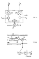
- Fig. 3 the basic structure of the compensator 25 for an intervention in the air mass flow L * is shown in more detail.
- Conventional sensors with electrical output signals such as thermocouples, resistance thermometers and pressure sensors, can be used as transducers 28 and 29 for sizes ⁇ L and p L.
- the further task now is to determine the relative change in the air mass flow as a function of the relative change in the air pressure and the air temperature in the simplest possible manner.
- this can be done by individually recording air pressure and temperature, appropriate weighting and offsetting according to (1).
- this extremely simple procedure is preferably used for the detection of the air mass flow changes caused by the main disturbance variable in the forced air burner system compensated for the disturbance variable, but can in principle be used wherever a change in gas density or change in gas mass flow as a function of the gas pressure and the gas temperature is to be recorded .
- a gas volume V is encapsulated in a closed container 30 for this purpose.
- the vessel 30 lies in the gas stream L *.
- T L T V applies.
- the difference between the static pressure p a in the gas stream L * and the pressure p V in the vessel 30 is measured by means of a differential pressure sensor 33.
- a differential pressure signal p a - p V appears at the output of the differential pressure sensor 33, which , based on the pressure p ao at reference ratios, equal to the relative change in density in the ambient gas L, which in turn, at at least almost constant volume flow V *, is at least almost equal to the gas mass flow change ⁇ L * with respect to the same reference ratios, ie L0 *.
- one condition is that the output signal of the differential pressure measurement by means of the sensor 33 is proportional to the relative density or gas mass flow change, that the gas of the flow L * and that in the vessel 30 are at the same temperatures.
- radiation protection 31 is therefore provided, which prevents thermal radiation from the outside and corresponding measurement errors.
- the closed vessel 30 is arranged on the fuel line 7 of a forced draft burner according to FIG. 2 with a fan 37.
- the differential pressure sensor 33 measures the pressure difference between the static pressure in the flowing combustion air and the gas pressure, preferably air pressure, in the vessel 30.
- the output signal swing of the sensor 33 is zero-symmetrical.
- the output signal of the differential pressure sensor 33 is fed to an amplifier 39, preferably with an adjustable gain.
- the fuel pressure in line 3 to the burner is regulated to a predetermined value by means of a schematically illustrated pressure regulating valve 41, the valve body 45 operating in the regulating sense against the force of a spring 43 additionally carrying a magnet armature 47 which runs in two fixed coils 49 and 51 .
- the coil 49 is activated via a diode D1 and a voltage / current converter 53, and at the other polarity of the output signal of the amplifier 39, the coil 51 is activated via an inverse polarized diode D2 and a voltage / current converter 55.
- a disturbance variable compensation shift is forced on the valve body 45 of the control valve 41 by the force of one of the coils 51, 49 in the correct polarity, and the actuating force of the control difference is superimposed, with which the effects of the main disturbance variables, namely the temperature and pressure changes in the combustion air, on the combustion by intervention be compensated for the fuel flow B *.
- the structure of the valve is shown in detail in DE-PS 3513282.
- pressure equalization between the container 30 and the air flow L * is achieved with the schematically illustrated valve 53, for example with an optimally adjusted burner.
Landscapes
- Engineering & Computer Science (AREA)
- Chemical & Material Sciences (AREA)
- Combustion & Propulsion (AREA)
- Mechanical Engineering (AREA)
- General Engineering & Computer Science (AREA)
- Regulation And Control Of Combustion (AREA)
- Air Supply (AREA)
- Incineration Of Waste (AREA)
Applications Claiming Priority (2)
| Application Number | Priority Date | Filing Date | Title |
|---|---|---|---|
| DE3812697 | 1988-04-16 | ||
| DE3812697A DE3812697A1 (de) | 1988-04-16 | 1988-04-16 | Verfahren zur reduzierung der stoergroessenwirkung bei geblaesebrenneranlagen und geblaesebrenneranlage |
Publications (3)
| Publication Number | Publication Date |
|---|---|
| EP0342347A2 true EP0342347A2 (fr) | 1989-11-23 |
| EP0342347A3 EP0342347A3 (en) | 1990-04-04 |
| EP0342347B1 EP0342347B1 (fr) | 1995-12-06 |
Family
ID=6352124
Family Applications (1)
| Application Number | Title | Priority Date | Filing Date |
|---|---|---|---|
| EP89106131A Expired - Lifetime EP0342347B1 (fr) | 1988-04-16 | 1989-04-07 | Méthode pour réduire l'effet de grandeurs déréglantes pour brûleurs à soufflerie et brûleurs à soufflerie |
Country Status (4)
| Country | Link |
|---|---|
| US (1) | US5106294A (fr) |
| EP (1) | EP0342347B1 (fr) |
| AT (1) | ATE131273T1 (fr) |
| DE (2) | DE3812697A1 (fr) |
Cited By (2)
| Publication number | Priority date | Publication date | Assignee | Title |
|---|---|---|---|---|
| US5369270A (en) * | 1990-10-15 | 1994-11-29 | Interactive Light, Inc. | Signal generator activated by radiation from a screen-like space |
| AT399219B (de) * | 1991-09-09 | 1995-04-25 | Vaillant Gmbh | Brennerbeheizter wasserspeicher |
Families Citing this family (19)
| Publication number | Priority date | Publication date | Assignee | Title |
|---|---|---|---|---|
| DE4109841C2 (de) * | 1991-03-26 | 1994-06-09 | Bosch Gmbh Robert | Regelvorrichtung für Gasbrenner mit einem Gebläse zum Zuführen von Verbrennungsluft |
| AT399234B (de) * | 1992-12-21 | 1995-04-25 | Vaillant Gmbh | Drucksensorik |
| US5722588A (en) * | 1994-04-13 | 1998-03-03 | Nippon Soken Inc. | Combustion heater |
| US5634786A (en) * | 1994-11-30 | 1997-06-03 | North American Manufacturing Company | Integrated fuel/air ratio control system |
| DE19510425C2 (de) * | 1995-03-24 | 1999-05-27 | Bosch Gmbh Robert | Verfahren und Vorrichtung zur Regelung eines Heizgerätes |
| US6363164B1 (en) | 1996-05-13 | 2002-03-26 | Cummins-Allison Corp. | Automated document processing system using full image scanning |
| US7136767B2 (en) * | 2002-06-24 | 2006-11-14 | Mks Instruments, Inc. | Apparatus and method for calibration of mass flow controller |
| US7809473B2 (en) | 2002-06-24 | 2010-10-05 | Mks Instruments, Inc. | Apparatus and method for pressure fluctuation insensitive mass flow control |
| US6712084B2 (en) | 2002-06-24 | 2004-03-30 | Mks Instruments, Inc. | Apparatus and method for pressure fluctuation insensitive mass flow control |
| US7033670B2 (en) * | 2003-07-11 | 2006-04-25 | Siemens Power Generation, Inc. | LCT-epoxy polymers with HTC-oligomers and method for making the same |
| US20050277721A1 (en) * | 2004-06-15 | 2005-12-15 | Siemens Westinghouse Power Corporation | High thermal conductivity materials aligned within resins |
| DE102004055716C5 (de) * | 2004-06-23 | 2010-02-11 | Ebm-Papst Landshut Gmbh | Verfahren zur Regelung einer Feuerungseinrichtung und Feuerungseinrichtung (Elektronischer Verbund I) |
| US7651963B2 (en) | 2005-04-15 | 2010-01-26 | Siemens Energy, Inc. | Patterning on surface with high thermal conductivity materials |
| DE102005025285B4 (de) * | 2005-06-02 | 2007-11-08 | Rolf Puhlmann | Messeinrichtung zur quasi kontinuierlichen Dichtebestimmung der Luft-Hauptkomponenten Sauerstoff und Stickstoff und deren Verwendung |
| US8357433B2 (en) | 2005-06-14 | 2013-01-22 | Siemens Energy, Inc. | Polymer brushes |
| US7781057B2 (en) * | 2005-06-14 | 2010-08-24 | Siemens Energy, Inc. | Seeding resins for enhancing the crystallinity of polymeric substructures |
| US20090142717A1 (en) * | 2007-12-04 | 2009-06-04 | Preferred Utilities Manufacturing Corporation | Metering combustion control |
| US8191387B2 (en) * | 2009-05-01 | 2012-06-05 | Owens-Brockway Glass Container Inc. | System and method for controlling temperature in a forehearth |
| DE102016117323B3 (de) * | 2016-09-14 | 2017-11-02 | Valeo Thermal Commercial Vehicles Germany GmbH | Verfahren zur Konstanthaltung des dem Brennerraum eines mobilen Heizgerätes zugeführten Verbrennungsluft-Massenstroms und nach einem solchen Verfahren arbeitendes Heizgerät |
Citations (6)
| Publication number | Priority date | Publication date | Assignee | Title |
|---|---|---|---|---|
| EP0086337A1 (fr) * | 1982-02-04 | 1983-08-24 | Programmelectronic Engineering Ag | Procédé et dispositif de réglage pour la régulation d'excès d'air dans les chauffages |
| JPS60105822A (ja) * | 1983-11-15 | 1985-06-11 | Kaneko Agricult Mach Co Ltd | バ−ナにおける燃焼制御装置 |
| US4583936A (en) * | 1983-06-24 | 1986-04-22 | Gas Research Institute | Frequency modulated burner system |
| DE3513282C1 (de) * | 1985-04-13 | 1986-06-12 | Programmelectronic Engineering AG, Dornach | Stellmotor |
| US4613072A (en) * | 1984-07-31 | 1986-09-23 | Mikuni Kogyo Kabushiki Kaisha | Apparatus for heating fluid by burning liquid fuel |
| GB2190515A (en) * | 1986-04-15 | 1987-11-18 | Julian Branford Todd | Regenerator control by flue recirculation |
Family Cites Families (12)
| Publication number | Priority date | Publication date | Assignee | Title |
|---|---|---|---|---|
| US424617A (en) * | 1890-04-01 | Thermostat | ||
| US2371428A (en) * | 1941-11-08 | 1945-03-13 | Liquidometer Corp | Remote regulation of atmospheric condition |
| US2470742A (en) * | 1944-03-06 | 1949-05-17 | Bendix Aviat Corp | Density responsive device |
| US2601777A (en) * | 1946-01-16 | 1952-07-01 | Niles Bement Pond Co | Density measuring device |
| US2638784A (en) * | 1951-03-19 | 1953-05-19 | Richard S Cesaro | Temperature sensing device |
| US3365932A (en) * | 1965-08-16 | 1968-01-30 | Ugc Instr Inc | Densitometer |
| US3701280A (en) * | 1970-03-18 | 1972-10-31 | Daniel Ind Inc | Method and apparatus for determining the supercompressibility factor of natural gas |
| US3818877A (en) * | 1972-08-24 | 1974-06-25 | Ford Motor Co | Signal generating process for use in engine control |
| US4050878A (en) * | 1974-05-16 | 1977-09-27 | Autotronic Controls Corporation | Electronic carburetion system for low exhaust emissions of internal combustion engines |
| JPS5566630A (en) * | 1978-11-13 | 1980-05-20 | Nissan Motor Co Ltd | Detector for density of suction air of internal combustion engine |
| JPS57166416A (en) * | 1981-04-04 | 1982-10-13 | Chugai Ro Kogyo Kaisha Ltd | Automatic air-fuel ratio controller of combustion equipment using preheated air |
| CH668825A5 (de) * | 1986-01-28 | 1989-01-31 | Landis & Gyr Ag | Verfahren und vorrichtung zur gas-luft-mengenregelung fuer gasgeblaesebrenner. |
-
1988
- 1988-04-16 DE DE3812697A patent/DE3812697A1/de active Granted
-
1989
- 1989-04-07 EP EP89106131A patent/EP0342347B1/fr not_active Expired - Lifetime
- 1989-04-07 AT AT89106131T patent/ATE131273T1/de active
- 1989-04-07 DE DE58909519T patent/DE58909519D1/de not_active Expired - Fee Related
-
1991
- 1991-03-14 US US07/670,367 patent/US5106294A/en not_active Expired - Fee Related
Patent Citations (6)
| Publication number | Priority date | Publication date | Assignee | Title |
|---|---|---|---|---|
| EP0086337A1 (fr) * | 1982-02-04 | 1983-08-24 | Programmelectronic Engineering Ag | Procédé et dispositif de réglage pour la régulation d'excès d'air dans les chauffages |
| US4583936A (en) * | 1983-06-24 | 1986-04-22 | Gas Research Institute | Frequency modulated burner system |
| JPS60105822A (ja) * | 1983-11-15 | 1985-06-11 | Kaneko Agricult Mach Co Ltd | バ−ナにおける燃焼制御装置 |
| US4613072A (en) * | 1984-07-31 | 1986-09-23 | Mikuni Kogyo Kabushiki Kaisha | Apparatus for heating fluid by burning liquid fuel |
| DE3513282C1 (de) * | 1985-04-13 | 1986-06-12 | Programmelectronic Engineering AG, Dornach | Stellmotor |
| GB2190515A (en) * | 1986-04-15 | 1987-11-18 | Julian Branford Todd | Regenerator control by flue recirculation |
Non-Patent Citations (1)
| Title |
|---|
| PATENT ABSTRACTS OF JAPAN, Band 9, Nr. 256 (M-421)(1979), 15. Oktober 1985; & JP,A,60 105 822 (KANEKO NOUKI K.K.) 11.06.1985. * |
Cited By (2)
| Publication number | Priority date | Publication date | Assignee | Title |
|---|---|---|---|---|
| US5369270A (en) * | 1990-10-15 | 1994-11-29 | Interactive Light, Inc. | Signal generator activated by radiation from a screen-like space |
| AT399219B (de) * | 1991-09-09 | 1995-04-25 | Vaillant Gmbh | Brennerbeheizter wasserspeicher |
Also Published As
| Publication number | Publication date |
|---|---|
| ATE131273T1 (de) | 1995-12-15 |
| US5106294A (en) | 1992-04-21 |
| EP0342347B1 (fr) | 1995-12-06 |
| DE3812697C2 (fr) | 1993-04-08 |
| DE58909519D1 (de) | 1996-01-18 |
| DE3812697A1 (de) | 1989-12-28 |
| EP0342347A3 (en) | 1990-04-04 |
Similar Documents
| Publication | Publication Date | Title |
|---|---|---|
| EP0342347A2 (fr) | Méthode pour réduire l'effet de grandeurs déréglantes pour brûleurs à soufflerie et brûleurs à soufflerie | |
| DE2921787C2 (de) | Thermischer Luft-Durchflußmesser für Brennkraftmaschinen | |
| EP1370806B1 (fr) | Procede et dispositif de reglage du rapport air/carburant | |
| EP0696708B1 (fr) | Méthode de régulation de la combustion pour installations de combustion, notammement d'installations d'incinérations de déchets | |
| DE60202855T2 (de) | Druckdampferzeuger und dessen steuerung | |
| DE2157722C2 (de) | Regelsystem für eine Brennstoffzelle | |
| DE3827978A1 (de) | Verfahren und vorrichtung fuer stetige lambdaregelung | |
| EP1002999A2 (fr) | Commande de la puissance d'un brûleur d' un appareil de cuisson à gaz | |
| DE3707258C2 (de) | Brennervorrichtung | |
| DE102008028189B4 (de) | Elektropneumatisches Ventil | |
| DE202019100261U1 (de) | Heizgerät mit Regelung eines Gasgemisches | |
| DE2605660A1 (de) | Pneumatischer bzw. gaschromatograph und chromatographisches verfahren | |
| DE3607386C2 (fr) | ||
| EP3734159A1 (fr) | Procédé de vérification d'un capteur de mélange gazeux dans un appareil chauffant fonctionnant au gaz combustible | |
| EP3746705A1 (fr) | Procédé de réglage d'un mélange gazeux au moyen d'un capteur de mélange gazeux | |
| DE102019110976A1 (de) | Verfahren zur Überprüfung eines Gasgemischsensors und Ionisationssensors bei einem brenngasbetriebenen Heizgerät | |
| EP0239842B1 (fr) | Procédé de réglage de la température intérieure d'un habitacle, notamment d'un véhicule automobile | |
| DE19941700C1 (de) | Vorrichtung zum Betreiben einer Heizungsanlage | |
| DE2209779B2 (de) | Heißgaskolbenmotor, bei dem die Brennstoffzufuhr zur Brennervorrichtung mittels eines auf wenigstens einen Parameter des Motors reagierendes Regelgeräts geregelt wird | |
| DE3202476C2 (de) | Vorrichtung zum Regeln der Temperatur in einem Ofen | |
| DE19831451A1 (de) | Verfahren und Vorrichtung zum Steuern bzw. Regeln eines Gasbrenners | |
| DE2101115C3 (de) | Stellvorrichtung zur Steuerung der Stellung eines beweglichen Gliedes mit einem federvorgespannten temperaturempfindlichen Element | |
| EP0158842B1 (fr) | Dispositif de régulation du rapport carburant/air d'une source de chaleur chauffée au carburant | |
| DE19808681A1 (de) | Wärmeleitgasanalysator mit kurzer Einstellzeit | |
| EP0644376B1 (fr) | Procédé et dispositif de régulation d'un brûleur |
Legal Events
| Date | Code | Title | Description |
|---|---|---|---|
| PUAI | Public reference made under article 153(3) epc to a published international application that has entered the european phase |
Free format text: ORIGINAL CODE: 0009012 |
|
| AK | Designated contracting states |
Kind code of ref document: A2 Designated state(s): AT BE CH DE ES FR GB GR IT LI LU NL SE |
|
| PUAL | Search report despatched |
Free format text: ORIGINAL CODE: 0009013 |
|
| AK | Designated contracting states |
Kind code of ref document: A3 Designated state(s): AT BE CH DE ES FR GB GR IT LI LU NL SE |
|
| 17P | Request for examination filed |
Effective date: 19900531 |
|
| RAP1 | Party data changed (applicant data changed or rights of an application transferred) |
Owner name: CONEL AG |
|
| 17Q | First examination report despatched |
Effective date: 19921012 |
|
| GRAA | (expected) grant |
Free format text: ORIGINAL CODE: 0009210 |
|
| AK | Designated contracting states |
Kind code of ref document: B1 Designated state(s): AT BE CH DE ES FR GB GR IT LI LU NL SE |
|
| PG25 | Lapsed in a contracting state [announced via postgrant information from national office to epo] |
Ref country code: IT Free format text: LAPSE BECAUSE OF FAILURE TO SUBMIT A TRANSLATION OF THE DESCRIPTION OR TO PAY THE FEE WITHIN THE PRE;WARNING: LAPSES OF ITALIAN PATENTS WITH EFFECTIVE DATE BEFORE 2007 MAY HAVE OCCURRED AT ANY TIME BEFORE 2007. THE CORRECT EFFECTIVE DATE MAY BE DIFFERENT FROM THE ONE RECORDED.SCRIBED TIME-LIMIT Effective date: 19951206 Ref country code: GR Free format text: LAPSE BECAUSE OF FAILURE TO SUBMIT A TRANSLATION OF THE DESCRIPTION OR TO PAY THE FEE WITHIN THE PRESCRIBED TIME-LIMIT Effective date: 19951206 Ref country code: BE Effective date: 19951206 Ref country code: ES Free format text: THE PATENT HAS BEEN ANNULLED BY A DECISION OF A NATIONAL AUTHORITY Effective date: 19951206 Ref country code: FR Effective date: 19951206 Ref country code: NL Free format text: LAPSE BECAUSE OF FAILURE TO SUBMIT A TRANSLATION OF THE DESCRIPTION OR TO PAY THE FEE WITHIN THE PRESCRIBED TIME-LIMIT Effective date: 19951206 Ref country code: GB Effective date: 19951206 |
|
| REF | Corresponds to: |
Ref document number: 131273 Country of ref document: AT Date of ref document: 19951215 Kind code of ref document: T |
|
| REF | Corresponds to: |
Ref document number: 58909519 Country of ref document: DE Date of ref document: 19960118 |
|
| PG25 | Lapsed in a contracting state [announced via postgrant information from national office to epo] |
Ref country code: SE Effective date: 19960306 |
|
| PG25 | Lapsed in a contracting state [announced via postgrant information from national office to epo] |
Ref country code: AT Effective date: 19960407 |
|
| PG25 | Lapsed in a contracting state [announced via postgrant information from national office to epo] |
Ref country code: CH Effective date: 19960430 Ref country code: LU Free format text: LAPSE BECAUSE OF NON-PAYMENT OF DUE FEES Effective date: 19960430 Ref country code: LI Effective date: 19960430 |
|
| NLV1 | Nl: lapsed or annulled due to failure to fulfill the requirements of art. 29p and 29m of the patents act | ||
| EN | Fr: translation not filed | ||
| GBV | Gb: ep patent (uk) treated as always having been void in accordance with gb section 77(7)/1977 [no translation filed] |
Effective date: 19951206 |
|
| PLBE | No opposition filed within time limit |
Free format text: ORIGINAL CODE: 0009261 |
|
| STAA | Information on the status of an ep patent application or granted ep patent |
Free format text: STATUS: NO OPPOSITION FILED WITHIN TIME LIMIT |
|
| 26N | No opposition filed | ||
| REG | Reference to a national code |
Ref country code: CH Ref legal event code: PL |
|
| PG25 | Lapsed in a contracting state [announced via postgrant information from national office to epo] |
Ref country code: DE Effective date: 19970101 |