EP0342230B1 - Winkelgeschwindigkeitssensor mit einer einzigen schwingachse - Google Patents
Winkelgeschwindigkeitssensor mit einer einzigen schwingachse Download PDFInfo
- Publication number
- EP0342230B1 EP0342230B1 EP89901220A EP89901220A EP0342230B1 EP 0342230 B1 EP0342230 B1 EP 0342230B1 EP 89901220 A EP89901220 A EP 89901220A EP 89901220 A EP89901220 A EP 89901220A EP 0342230 B1 EP0342230 B1 EP 0342230B1
- Authority
- EP
- European Patent Office
- Prior art keywords
- accelerometers
- axis
- support members
- axes
- accelerometer
- Prior art date
- Legal status (The legal status is an assumption and is not a legal conclusion. Google has not performed a legal analysis and makes no representation as to the accuracy of the status listed.)
- Expired - Lifetime
Links
- 230000001133 acceleration Effects 0.000 claims abstract description 68
- 230000033001 locomotion Effects 0.000 claims abstract description 25
- 230000001154 acute effect Effects 0.000 claims abstract description 4
- 238000006073 displacement reaction Methods 0.000 claims description 10
- 239000013598 vector Substances 0.000 claims description 9
- 238000012545 processing Methods 0.000 claims description 8
- 230000008878 coupling Effects 0.000 claims description 5
- 238000010168 coupling process Methods 0.000 claims description 5
- 238000005859 coupling reaction Methods 0.000 claims description 5
- 230000000737 periodic effect Effects 0.000 claims description 4
- 238000004519 manufacturing process Methods 0.000 claims 1
- 230000006835 compression Effects 0.000 abstract 1
- 238000007906 compression Methods 0.000 abstract 1
- 230000008901 benefit Effects 0.000 description 5
- 238000012937 correction Methods 0.000 description 5
- 238000000034 method Methods 0.000 description 5
- 238000009527 percussion Methods 0.000 description 5
- 230000008859 change Effects 0.000 description 4
- 230000035945 sensitivity Effects 0.000 description 4
- 238000010586 diagram Methods 0.000 description 3
- 230000000694 effects Effects 0.000 description 3
- 238000006880 cross-coupling reaction Methods 0.000 description 2
- 238000013461 design Methods 0.000 description 2
- 230000006870 function Effects 0.000 description 2
- 230000008569 process Effects 0.000 description 2
- 230000009466 transformation Effects 0.000 description 2
- 238000013459 approach Methods 0.000 description 1
- 238000005452 bending Methods 0.000 description 1
- 238000006243 chemical reaction Methods 0.000 description 1
- 239000004020 conductor Substances 0.000 description 1
- 230000000593 degrading effect Effects 0.000 description 1
- 230000005284 excitation Effects 0.000 description 1
- 229910052737 gold Inorganic materials 0.000 description 1
- 230000001939 inductive effect Effects 0.000 description 1
- 238000005259 measurement Methods 0.000 description 1
- 239000002184 metal Substances 0.000 description 1
- 230000000135 prohibitive effect Effects 0.000 description 1
- 230000004044 response Effects 0.000 description 1
- 238000000926 separation method Methods 0.000 description 1
- 230000001360 synchronised effect Effects 0.000 description 1
- 238000000844 transformation Methods 0.000 description 1
Images


Classifications
-
- G—PHYSICS
- G01—MEASURING; TESTING
- G01C—MEASURING DISTANCES, LEVELS OR BEARINGS; SURVEYING; NAVIGATION; GYROSCOPIC INSTRUMENTS; PHOTOGRAMMETRY OR VIDEOGRAMMETRY
- G01C19/00—Gyroscopes; Turn-sensitive devices using vibrating masses; Turn-sensitive devices without moving masses; Measuring angular rate using gyroscopic effects
- G01C19/56—Turn-sensitive devices using vibrating masses, e.g. vibratory angular rate sensors based on Coriolis forces
- G01C19/5705—Turn-sensitive devices using vibrating masses, e.g. vibratory angular rate sensors based on Coriolis forces using masses driven in reciprocating rotary motion about an axis
-
- G—PHYSICS
- G01—MEASURING; TESTING
- G01C—MEASURING DISTANCES, LEVELS OR BEARINGS; SURVEYING; NAVIGATION; GYROSCOPIC INSTRUMENTS; PHOTOGRAMMETRY OR VIDEOGRAMMETRY
- G01C19/00—Gyroscopes; Turn-sensitive devices using vibrating masses; Turn-sensitive devices without moving masses; Measuring angular rate using gyroscopic effects
- G01C19/56—Turn-sensitive devices using vibrating masses, e.g. vibratory angular rate sensors based on Coriolis forces
- G01C19/5776—Signal processing not specific to any of the devices covered by groups G01C19/5607 - G01C19/5719
Definitions
- the present invention is directed to an apparatus and method for sensing acceleration and angular rate of rotation of a body, wherein such apparatus includes a plurality of accelerometers used for measuring the linear acceleration and angular rate of rotation of the body, preferably with respect to three orthogonal axes.
- the rate of rotation of a body about an axis may be determined by mounting an accelerometer on a moving frame, with the accelerometer's sensitive axis and the direction of motion of the flame both normal to the rate axis about which rotation is to be measured. For example, consider a set of orthogonal axes, X, Y and Z fixed in a body. Periodic movement of an accelerometer along the Y axis of the body with its sensitive axis aligned with the Z axis results in the accelerometer experiencing a Coriolis acceleration directed along the Z axis as the body rotates about the X axis.
- the acceleration or force acting on the accelerometer is proportional to a change in velocity of the body along the Z axis and its angular rate of rotation about the X axis.
- An output signal from the accelerometer thus includes a DC or slowly changing component representing the linear acceleration of the body along the Z axis, and a periodic component representing the Coriolis acceleration resulting from rotation of the body about the X axis.
- a preferred embodiment of a rotational rate sensor in which two accelerometers are mounted in a parallelogram structure with their sensitive axes parallel or antiparallel.
- the two accelerometers are vibrated back and forth in a direction substantially normal to their sensitive axes.
- An electromagnetic D'Arsonval coil mounted at one side of the parallelogram structure is energized with a periodically varying current, attracting a pole piece that is attached to the parallelogram structure.
- the varying magnetic attractive force of the coil causes the structure to vibrate, dithering the accelerometers back and forth.
- a signal processor connected to the pair of accelerometers combines their output signals, deriving both a rate signal and a linear acceleration signal.
- Three such dithering parallelogram frame structures wherein the sensitive axes of the associated accelerometer pairs are aligned along orthogonal axes, may be used to fully define the linear acceleration and angular rate of rotation experienced by a body.
- the total volume of three parallelogram structures may exceed the space available in certain applications.
- the cost of such a device may be prohibitive for a particular use.
- the sensitive axes of the two accelerometers are aligned in parallel with the central dither axis and, in another embodiment, the two accelerometers are mounted on the disk back-to-back, with their sensitive axes radially aligned normal to the dither axis. Because the pointing direction of their sensitive axes is continually changing as the accelerometers rotate back and forth, the signal produced by the pair of accelerometers has an undesirable cross-axis vibration sensitivity, i.e., vibrations in a direction nonaligned with the sensitive axis couple into the accelerometer's output signal as an error component.
- an apparatus and method for sensing angular rate of rotation about each of a plurality of axes are disclosed.
- the apparatus includes a supporting base to which are pivotally connected a first and a second frame member.
- the frame members are free to rotate about a common axis.
- Mounted on the first and second frame members are a plurality of pairs of accelerometers, each accelerometer having an acceleration sensitive axis.
- Each pair of accelerometers is associated with one of a plurality of prime axes about which the angular rate of rotation is sensed.
- the pairs of accelerometers are mounted on the first and second frame members so that the acceleration sensitive axes of the two accelerometers comprising a pair are generally in parallel alignment.
- an apparatus for sensing the angular rate of rotation of a body about a prime axis comprises a first accelerometer and a second accelerometer mounted on opposed support members that are pivotally connected to the body.
- Driving means are operative to counter-rotate the first and the second frame members in a dither motion in opposite directions about the common axis without transmitting a reaction force to the supporting base.
- the counter-rotating motion of each pair of accelerometers about the common axis causes them to experience a Coriolis acceleration proportional to the angular rate of rotation about the prime axis with which the pair of accelerometers is associated, and each accelerometer of the pair produces an output signal that is a function of the Coriolis acceleration.
- Signal processing means connected to the accelerometers are operative to determine the angular rate of rotation about each of the prime axes, and are further operative to determine a linear acceleration along each of the three orthogonal prime axes.
- the driving means include first and second electromagnetic coils and pole pieces.
- the electromagnetic coils and their associated pole pieces are connected to one of the first and second frame members, an electromagnetic coil being attached to one frame member and the pole piece to the other frame member.
- a periodically varying current sequentially energizes the first and second electromagnetic coils so that the frame members dither back and forth, in counter-rotation relative to each other.
- the apparatus further includes means for sensing an angular displacement of the first frame member relative to the second and for producing a signal indicative of the angular displacement.
- Drive control means connected to receive the signal indicative of angular displacement are operative to control the amplitude and phase of the periodically varying current used to energize the first and second electromagnetic coils, as a function of that signal.
- the supporting base includes a baseplate and a plurality of flexures that connect the baseplate to the first and second frame members, at spaced apart points around the common axis.
- the flexures comprise elongate flat strips, which have a surface aligned with a common axis and which extend between the first and second frame members, opposite ends of each strip being connected thereto. An intermediate point of the flexible strips is connected to the baseplate.
- the baseplate includes a plurality of tabs that extend radially outward relative to the common axis. These tabs are adapted to connect to a body subject to rotation about the prime axes.
- both accelerometers of a pair are mounted on the same frame member.
- one accelerometer of each pair is mounted on the first frame member and the other is mounted on the second frame member.
- One embodiment includes eight accelerometers, and another six.
- the prime axes define orthogonal planes in which lie the acceleration sensitive axes of the accelerometers.
- prime axes are defined by the acceleration sensitive axes.
- rate sensor 10 includes a baseplate 12, which is generally formed in the shape of a "T".
- the top portion of the "T” comprises two symmetric outwardly extending tabs 14, while the vertical portion includes a third outwardly extending tab 16.
- Baseplate 12 is sized so that tabs 14 and 16 extend beyond the circumference of the remainder of the rate sensor, exposing three mounting holes 18 formed in the outer ends of the tabs. Mounting holes 18 thus adapt baseplate 12 for attachment to a moving body by use of a suitable fastener, enabling measurement of the linear acceleration and angular rate of rotation to which the body is subject, with respect to three orthogonal axes.
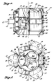
- Rate sensor 10 further includes an upper frame member 20 and lower frame member 22, each of which have a generally hemispherically shaped external surface, although the sides of each of the frame members 20 and 22 are relieved forming indented flat areas at three spaced-apart locations around their circumference.
- the outer top surface of upper frame member 20 includes three ports 24, which are sized to accommodate accelerometers 26a, 28a and 30a. Ports 24 are formed in upper frame member 20, and are directed outwardly at an acute angle relative to an axis 40 that extends through the center of the upper frame member.
- the angle formed between each of the centerlines of ports 24 and axis 40 is preferably equal to 35.26°; the significance of this angle is discussed hereinbelow.
- the lower frame member 22 also includes three ports 25 similarly sized to accommodate accelerometers 26b, 28b and 30b (see FIGURE 5), and are angled inwardly toward that axis, as it extends through lower frame member 22.
- the centerlines of ports 25 define an acute angle with axis 40 equal to that similarly defined by the centerlines of ports 24.
- Accelerometer 26a is mounted in one of the ports 24 with its sensitive axis aligned along the centerline of that port and antiparallel to the sensitive axis of accelerometer 26b, which is mounted in one of the ports 25.
- accelerometers 28a and 30a have their sensitive axes in antiparallel alignment with the sensitive axes of accelerometers 28b and 30b, respectively.
- the six accelerometers 26, 28 and 30 thus comprise pairs of accelerometers wherein one accelerometer of a pair is mounted on the upper frame member 20 and the other is mounted on the lower frame member 22.
- the accelerometers be mounted with their sensitive axes in antiparallel alignment
- the present invention is equally applicable to pairs of accelerometers mounted with their sensitive axes in parallel alignment, simply by inverting the output signal of one of the accelerometers.
- parallel as used in the claims, is intended to encompass both the arrangement in which each accelerometer of a pair has its positive sensitive axis aligned and pointing generally in the same direction as the other, and that described above wherein the sensitive axes are aligned and are pointing generally in opposite directions, i.e., both the more specifically defined parallel and anti-parallel arrangements.
- Upper frame member 20 is connected to baseplate 12 and to lower frame member 22 by six flex links 32, formed of elongate, relatively thin sheet metal strips. Flex links 32 extend between the upper and lower frame members 20 and 22, and are connected thereto and to baseplate 12 using screws 34 or other suitable fasteners. (In FIGURE 3, only a single exemplary screw 34 is shown for simplicity).
- a plurality of flat surfaces 36 are formed on the sides of tabs 14 and 16 of baseplate 12, in radial alignment with axis 40, providing a flat mount on which the center portion of flex links 32 may be attached.
- a plurality of radially aligned flat surfaces 38 are formed on the upper and lower frame members 20 and 22 for attachment of the upper and lower ends of flex links 32.
- flex links 32 may bend cross-axis, permitting the upper and lower frame members to rotate slightly about axis 40, relative to fixed baseplate 12. However, they are relatively stiff or rigid under compressive loads directed along or parallel to axis 40. Their radial alignment relative to axis 40 resists almost any other mode of motion relative to baseplate 12 except rotation about axis 40.
- the fact that flex links 32 provide the required rotational freedom yet are very resistant to other relative motions between the upper and lower frame members and the baseplate provide a substantial advantage compared to prior art rate sensors.
- the symmetry, axial stiffness, and radial alignment of the flex links helps to prevent cross-axis accelerations to which baseplate 12 is subject, from coupling into the signal output from the pairs of accelerometers as an error component.
- An electromagnetic coil 42 is mounted in two of the recessed portions of baseplate 12 and of upper and lower frame members 20 and 22.
- the electromagnetic coils provide a driving force that counter-rotates upper frame member 20 relative to lower frame member 22.
- the disposition of electromagnetic coils 42 is illustrated in FIGURE 4, and partially in FIGURE 1.
- a "C-shaped" core (not separately referenced by number) within electromagnetic coil 42 includes a pole face 48 at each end, which is disposed opposite a bar-shaped pole piece 50.
- Electromagnetic coil 42 is attached to the lower frame member 22 with the bracket 44, using bolts 46, or other suitable fasteners.
- a plate 45 clamps the electromagnetic coil 42 in place on bracket 44, mounting it rigidly to the lower frame member.
- Axis 40 thus comprises a dither axis about which accelerometer pairs 26, 28 and 30 are counter-rotated back and forth in a rotational dither motion.
- the dither motion causes the accelerometers to experience Coriolis forces as the body to which the rate sensor 10 is attached is subject to angular rotation.
- accelerometers 26, 28 and 30 respond to linear acceleration in alignment with their sensitive axes, thereby producing a signal which includes components of both Coriolis acceleration, i.e., angular rate, and of linear acceleration.
- Link 56 extends between upper frame member 20 and lower frame member 22 in the third indented flat area of those elements.
- Link 56 includes an open oval frame 62 having three spaced apart hubs 60 disposed in its interior, which are connected by means of flexible struts 58 to the inside surface of the frame.
- Each of the hubs 60 are connected to one of the upper frame member 20, baseplate 12, and lower frame member 22 using screws 64, or other suitable fasteners.
- Rate sensor 10 also includes a dither motion sensor for determining the amplitude and phase relationship of the dither motion followed by the upper and lower frame members 20 and 22 as they counter-rotate back and forth relative to each other.
- That sensor comprises an "E-coil" 66, which is attached to the upper frame member 20 using a bracket 68 and plate 69.
- a pole piece 70 is mounted adjacent to the "E-coil” with a bracket 72 that is attached to the lower frame member 22 using bolts 74, or other suitable fasteners, and a plate 73.
- Brackets 68 and 72 extend outwardly to mount the "E-coil” 66 and pole piece 70 so that they clear the surface of link 56.
- the "E-coil” 66 and pole piece 70 move relative to each other, changing the coupling between a plurality of coils comprising the "E"-shaped core of the coil, producing an electrical feedback signal indicative of the amplitude of the dither motion.
- This feedback signal is used to control the amplitude and phase relationship of the drive signal applied to electromagnetic coils 42.
- electromagnetic coils 42 and pole pieces 50 comprise a reactionless drive, in which the inertial moment of the upper frame member 20 cancels the inertial moment of the lower frame member 22. Consequently, no torque or vibration is transmitted to baseplate 12 or to the body to which it is attached.
- This provides a substantial advantage compared to prior art vibrating and rotating rate sensor structures, which may induce vibration into the body to which they are connected. Such vibrations may also cause cross-coupling errors between pairs of accelerometers in a three axes rate sensor of the prior art vibrating and rotating types.
- all of the accelerometers are dithered in synchronization at a common dither frequency, about a common dither axis 40.
- the synchronized signals they produce are therefore easier to process, and provide angular rate and linear acceleration data subject to few of the errors that troubled prior art schemes in which accelerometers either individually or in pairs were rotated in a single direction about an axis. Since accelerometers 26, 28 and 30 are dithered through a very small angle about dither axis 40, leads (not shown) may be easily attached directly to the accelerometers. Slip rings or other noise inducing electrical contacts are not required.
- FIGURES 6 and 7 The relationship between the sensitive axes for each pair of accelerometers 26, 28 and 30 relative to the angular rate axes P, Q and R are graphically illustrated in FIGURES 6 and 7. As shown in these FIGURES, the acceleration sensitive axes of the pairs of accelerometers 26, 28 and 30 are indicated by the vectors a x , a y and a z , respectively, and the angular rates, P, Q, and R, corresponding to the rate of angular rotation about the X, Y and Z axes are shown by the dashed vector lines.
- the length of the vectors and rate axes are entirely arbitrary and not intended to represent the magnitude of the vectors.
- the values for angular rate are determined by adding the demodulated output signals from each accelerometer in the pairs of accelerometers 26, 28 and 30. As represented in FIGURE 7, it may not be apparent that the angular rates, P, Q and R, define three orthogonal axes. However, by showing the rate axes aligned along the edges of a three-dimensional (imaginary) cube converging at one of its corners, as illustrated in FIGURE 6, the orthogonal relationship of the rate axes is readily perceived.
- the sensitive axes of each pair of accelerometers a x , a y and a z are aligned with diagonals of the cube, forming an angle of 35.26° with the dither axis 40.
- the sensitive axes of the pairs of accelerometers are not orthogonal to each other, although they lie within orthogonal planes defined by the rate axes, P, Q and R. Accordingly, it is relatively easy to transform the values for acceleration along the sensitive axes in terms of their component vectors to obtain orthogonal linear acceleration values along the rate axes, and to correct the rate of rotation determined by the non-orthogonal sensitive axes.
- the angular rate axes are orthogonal to each other, it is not necessary to transform the results obtained for those rate axes as was done above for the linear acceleration along the X, Y and Z axes. Accordingly, the results of the calculation for angular rate are substantially more accurate than would be the case if such a transformation were required, due to gain sensitivity. Since the values for angular rate are normally required at a much higher accuracy than the values for linear acceleration, the configuration defined for the first embodiment provides a substantial advantage compared to other embodiments contemplated by the present invention in which the accelerometers would be mounted at other angles, such as 45° relative to the dither axis 40.
- FIGURES 8, 9 and 10 conceptually illustrate a second embodiment of the present invention, rate sensor 100, using four pairs of accelerometers 102, 104, 106 and 108.
- the illustrations of the second embodiment merely show the disposition of the accelerometers on upper and lower counter-rotating members 112 and 114, relative to a baseplate 110.
- the counter-rotating members and baseplate, electromagnetic coils, "E-coil,” etc., as shown and described for rate sensor 10 may be provided in analogous fashion for rate sensor 100.
- the dither axis 40 passes through the centers of baseplate 110, and of counter-rotating members 112 and 114 normal to their upper and lower surfaces.
- the four accelerometers 102a, 102b, 104a and 104b rotate about dither axis 40 in one direction, as accelerometers 106a, 106b, 108a, and 108b rotate in the opposite direction, in a reactionless drive similar to that of rate sensor 10.
- Rate sensor 100 differs significantly from rate sensor 10 not only in the number of accelerometers used, but also in respect to the counter-rotating (frame) members on which each accelerometer of a pair is mounted.
- accelerometer 102a is mounted with its sensitive axis aligned in parallel with the sensitive axis of accelerometer 102b; however, both accelerometers 102a and 102b are mounted on the same counter-rotating member 112 rather than on different counter-rotating members.
- Each of the other pairs of accelerometers 104, 106, and 108 are similarly configured so that both accelerometers of a like numbered pair have their sensitive axes aligned and are mounted to the same counter-rotating member.
- each accelerometer of like numbered pairs has its sensitive axis pointing in an opposite direction, i.e., in antiparallel relationship to the other.
- the sensitive axes of the accelerometers in each pair form an angle of 45° relative' to the dither axis 40, and as shown in FIGURE 9, the accelerometers of each pair are disposed diametrically opposites each other at opposite sides of the counter-rotating member on which they are mounted.
- a u A a - A b (4)
- a a corresponds to the acceleration signal provided by accelerometer 102a
- a b corresponds to the acceleration signal from accelerometer 102b.
- accelerometers 108a and 108b which are mounted directly below accelerometers 102, on the lower counter-rotating member 114, the pointing angle change in the X axis can be eliminated.
- the term "pointing angle” refers to the angle subtended by the sensitive axes of the accelerometers as they are dithered back and forth.
- the effects of the change in the direction of the sensitive axes are equal and opposite for the upper and lower pairs of accelerometers associated with the same axis, such as 102 and 108, and therefore cancel.
- the Z component, aligned with the dither axis 40 remains in the X-Z plane at all times and does not change as the accelerometer pairs dither back and forth.
- accelerometers 104a and 104b and 106a and 106b can be used to develop the angular rate relative to the Y axis, Q in a similar fashion.
- the average pointing direction of both the rate and acceleration axes stays exactly aligned with the X and Y axes at each instant of time. This factor reduces the cross-axis acceleration and rate coupling errors associated with more conventional vibrating or rotating rate sensors.
- accelerometers in each pair are mounted on the same counter-rotating member, sinusoidal rate component error in the linear channels are eliminated.
- the linear acceleration component errors in the rate channels cancel when the demodulated output signals from each accelerometer are added.
- pairs of accelerometers in other dispositions on the counter-rotating members, as for example with pairs disposed at 90° spaced-apart intervals around each rotating member.
- a mounting disposition is not preferred, because the upper and lower counter-rotating members may have small, dissimilar mechanical motions which may degrade the cancellation of cross-coupling errors discussed above.
- the first embodiment of the present invention is preferred to the second embodiment for several reasons, other than the readily apparent reason that fewer accelerometers are required to implement it.
- FIGURES 11 and 12 a substantial advantage of the first embodiment relative to the second is grapically illustrated.
- one pair of accelerometers 102a and 102b is mounted on an upper counter-rotating member 112, and the accelerometers have their sensitive axes 102a' and 102b' aligned with each other, forming a 45° angle relative to the dither axis 40.
- accelerometers 108a and 108b are disposed on a lower counter-rotating member 114 with their sensitive axes 108a and 108b aligned antiparallel to each other, at 45° to dither axis 40.
- the centers of percussion of each of the accelerometers 102 and 108 are disposed at a radius r from the dither axis 40, and the sensitive axis 102a' is separated by a distance d from the sensitive axis 102b'.
- accelerometers 30a and 30b may be moved closer together, reducing d1 but not affecting r1 and r2, the distances between the centers of percussion of the accelerometers and the dither axis.
- the d1 term can be made nominally zero, effectively canceling out the error components due to angular acceleration.
- the value of d1 becomes less even though r1 is equal to r2. Since the accelerometers in the first embodiment are all mounted at an angle of 35.26° relative to the dither axis rather than the substantially larger 45° angle of the accelerometers in the second embodiment, they have even less sensitivity to centrifugal acceleration errors.
- FIGURE 13 a system for processing the signals output from each pair of accelerometers in the rate sensor is shown, with respect to a single pair of accelerometers 26a and 26b.
- accelerometers 26a and 26b These accelerometers produce an output signal proportional to the acceleration to which they are exposed along their sensitive axis, containing components of both angular rate and linear acceleration.
- the signals output from accelerometers 26a and 26b are conveyed by leads 120 and 122, respectively, to counters 124 and 126. These counters are operative to demodulate the signal by comparison with a signal SGN cos ⁇ t input via leads 128 from a timing and control circuit 130.
- the output from counters 124 and 126 is input over data lines 132 to a microprocessor 134.
- the microprocessor includes both read-only memory (ROM) in which a digital program is stored for processing the information and random access memory (RAM), which provides temporary storage for data.
- Microprocessor 134 processes the information provided by counters 124 and 126 to determine both the angular rate and linear acceleration components of the signals output from accelerometers 26a and 26b (and from each of the other pairs of accelerometers comprising the rate sensor).
- Microprocessor 134 also provides a timing and control signal through a conductor 136 to a timing and control block 130, which controls drive signal generator 138, in response to a signal from "E-coil” 66, conveyed over leads 140.
- Drive signal generator 138 produces a sinusoidally varying current to energize electromagnetic coils 42 (not shown in FIGURE 13) to reactionlessly dither upper frame member 20 and lower frame member 22 in counter-rotation relative to each other.
Landscapes
- Engineering & Computer Science (AREA)
- Physics & Mathematics (AREA)
- General Physics & Mathematics (AREA)
- Radar, Positioning & Navigation (AREA)
- Remote Sensing (AREA)
- Signal Processing (AREA)
- Gyroscopes (AREA)
Claims (17)
- Vorrichtung zum Abtasten der Winkelrotationsgeschwindigkeit eines Körpers um eine Hauptachse mit(a) einem ersten (26a) und einem zweiten Beschleunigungsmesser (26b) mit je einer beschleunigungs-empfindlichen Achse, die beide ein der Beschleunigung auf dieser Achse proportionales Signal erzeugen, wobei die beiden Beschleunigungsmesser an gegenüberliegenden, mit dem Körper gelenkig verbundenen Stützgliedern (20, 22) angebaut sind und die beschleunigungs-empfindlichen Achsen der beiden Beschleunigungsmesser allgemein parallel zueinander verlaufen;b) einem Motor (42, 50), der eine gegensinnige hin- und herzitternde Drehbewegung der sich gegenüberliegenden Stützglieder um eine gemeinsame Gelenkachse bewirkt, wobei die Rotation des Körpers um die Hauptachse eine Coriolis-Beschleunigung auf die gegensinnig drehenden Beschleunigungsmesser in Funktion der Winkelrotationsgeschwindigkeit ausübt, und dadurch verursacht, daß die Beschleunigungsmesser ein einer Komponente der Coriolos-Beschleunigung proportionales Signal erzeugen, das in gerader Linie mit deren beschleunigungs-empfindlichen Achsen verläuft, undc) Mitteln (134), mit denen durch Kombination der von den beiden Beschleunigungsmessern erzeugten Signale ein Ausgangssignal erzeugt wird, das die Winkelrotationsgeschwindigkeit des Körpers um die Hauptachse und wahlweise auch die auf den Körper in gerader Linie mit den beschleunigungs-empfindlichen Achsen der beiden Beschleunigungsmesser ausgeübte Beschleunigungsstärke anzeigt.
- Vorrichtung gemäß Anspruch 1, bei der der Motor (42, 50) zwei Elektromagneten (42) enthält, die sequentiell mit einem periodisch regelbarem Strom erregt werden und dadurch verursachen, daß die sich gegnüberliegenden Stützglieder (20, 22) in zueinander gegensinniger Bewegung hin- und herzittern.
- Vorrichtung gemäß Anspruch 2, bei der die beiden Elektromagneten (42) je eine elektromagnetische Spule (42) und einen Polschuh (50) aufweisen, wobei die Spule an dem einen und der Polschuh an dem anderen der sich gegenüberliegenden Stützglieder befestigt ist.
- Vorrichtung gemäß einem der vorhergehenden Ansprüche, ferner mit einer Grundplatte (12), die zwischen den sich gegenüberliegenden Stützgliedern (20, 22) angeordnet und mit dem Körper verbunden ist, wobei die sich gegenüberliegenden Stützglieder durch eine Mehrzahl von mit Winkelabstand voneinander angeordneten Biegeelementen (32) mit der Grundplatte gelenkig verbunden sind, wobei jedes Biegeelement eine zur gemeinsamen Gelenkachse radial ausgerichtete Langleiste mit Planfäche aufweist und jede Leiste an ihren Enden mit den sich gegenüberliegenden Stützgliedern und an einem Punkt zwischen den beiden Enden mit der Grundplatte verbunden ist.
- Vorrichtung gemäß einem der vorhergehenden Ansprüche, weiterhin mit Mitteln (66), die die Winkelverschiebung des ersten Beschleunigungsmessers relativ zum zweiten Beschleunigungsmesser abtasten und ein die Winkelverschiebung anzeigendes Signal (140) erzeugen; und wobei die die Signale kombinierenden Mittel (134) das die Winkelverschiebung anzeigende Signal (140) empfangen und des weiteren Amplitude und Phase eines periodischen Antriebsstroms steuern, der in Funktion des Signals (140) den Motor (42, 50) erregt.
- Vorrichtung zum Abtasten einer Winkelrotationsgeschwindigkeit um eine Mehrzahl von Hauptachsen mit(a) einem Träger (12);(b) einem ersten Stützglied (20) und einem zweiten Stützglied (22), die mit dem Träger gelenkig verbunden sind und somit um eine gemeinsame Achse drehen;(c) einer Mehrzahl von Beschleunigungsmesserpaaren (26, 28, 30) mit jeweils einer beschleunigungs-empfindlichen Achse, wobei jedes Beschleunigungsmesserpaar einer der Mehrzahl von Hauptachsen, um die die Winkelrotationsgeschwindigkeit abgetastet wird, zugeordnet ist, wobei die Beschleunigungsmesserpaare an den ersten und zweiten Stützgliedern angebaut sind, so daß die beschleunigungs-empfindlichen Achsen jeder zwei ein Paar formenden Beschleunigungsmesser allgemein parallel zueinander verlaufen;(d) Antriebsmitteln (42, 50), die bewirken, daß das erste Stützglied (20) gegensinning zum zweiten Stützglied (22) hin- und herzitternd um die gemeinsame Achse gedreht wird, daß jeder Beschleunigungsmesser um die gemeinsame Achse dreht, und daß auf jedes Beschleunigungsmesserpaar eine zur Winkelrotationsgeschwindigkeit um die zugehörige Hauptachse proportionale Coriolis-Beschleunigung ausgeübt wird, so daß jeder Beschleunigungsmesser ein Ausgangssignal in Funktion der Coriolos-Beschleunigung erzeugt; und(e) an die Beschleunigungsmesserpaare angeschlossenen Signalverarbeitungsmitteln (134) zur Verarbeitung der von den Beschleunigungsmessern erzeugten Signale, aus denen die Winkelrotationsgeschwindigkeit um jede der Hauptachsen und wahlweise auch die Beschleunigungsstärke entlang jeder der beschleunigungs-empfindlichen Achsen der Beschleunigungsmesser bestimmt werden.
- Vorrichtung gemäß Anspruch 6, bei der die Antriebsmittel (42, 50) eine erste elektromagnetische Spule (42), die mit dem einen der beiden Stützglieder verbunden ist, und einen ersten Polschuh (50), der mit dem anderen der beiden Stützglieder verbunden ist, eine zweite elektromagnetische Spule (42), die mit dem einen der beiden Stützglieder verbunden ist, und einen zweiten Polschuh (50), der mit dem anderen der beiden Stützglieder verbunden ist, aufweisen, wobei die beiden elektromagnetischen Spulen sequentiell erregt werden, derart, daß die zweite elektromagnetische Spule und der zweite Polschuh eine der Antriebskraft der ersten elektromagnetischen Spule und des ersten Polschuhs winklig entgegengerichtete Antriebskraft liefern.
- Vorrichtung gemäß Anspruch 7, bei der die beiden elektromagnetischen Spulen jeweils mit einem periodisch regelbaren Strom erregt werden, der eine Drehbewegung des ersten Stützgliedes (20) in gegenüber dem zweiten Stützglied (22) gegensinniger Richtung in einer ersten Richtung und dann in einer der ersten Richtung entgegengesetzten zweiten Richtung bewirkt, so daß beide Stützglieder in zueinander gegensinniger Richtung hin- und herzittern.
- Vorrichtung gemäß Anspruch 8, weiterhin mit Mitteln (66) zum Abtasten der Winkelverschiebung des ersten Stützgliedes (20) gegenüber dem zweiten Stützglied (22) und Erzeugung eines diese Winkelverschiebung anzeigenden Signals (140); und wobei die Signalverarbeitungsmittel (134) das die Winkelverschiebung anzeigende Signal (140) empfangen und des weiteren Amplitude und Phase des periodisch regelbaren Stromes steuern, der zur Erregung der beiden elektromagnetischen Spulen (42) in Funktion dieses Signals dient.
- Vorrichtung gemäß einem der Ansprüche 6 bis 9, bei der der Träger (12) aus einer zwischen den beiden Stützgliedern (20, 22) angeordneten Grundplatte besteht, die mit den Rahmengliedern über eine Mehrzahl von mit Winkelabstand angeordneten Biegelementen (32) verbunden ist, die jeweils eine mit der gemeinsamen Achse der beiden Stützglieder radial fluchtende Planfläche aufweisen, wobei jede Leiste an ihren Enden mit dem ersten bzw. zweiten Stützglied (20, 22) und an einem Punkt zwischen den Enden jeder Leiste mit der Grundplatte (12) verbunden ist.
- Vorrichtung gemäß einem der Ansprüche 6 bis 10, bei der der Träger (12) eine Mehrzahl von Vorsprüngen (14, 16) enthält, die ausgehend von der gemeinsamen Achse der ersten und zweiten Stützglieder (20, 22) radial nach außen weisen, wobei diese Vorsprünge zur Befestigung der Vorrichtung an einem um die Hauptachsen drehenden Körper dienen.
- Vorrichtung gemäß einem der Ansprüche 6 bis 11, bei der eine Beschleunigungsmesser jedes Paares am ersten Stützglied (20) und der andere Beschleunigungsmesser jedes Paares am zweiten Stützglied (22) angeordnet ist.
- Vorrichtung gemäß einem der Ansprüche 6 bis 12, bei der die Hauptachsen senkrecht zueinander stehen und bei der die beschleunigungs-empfindlichen Achsen der Beschleunigungsmesserpaare mit der gemeinsamen Achse der ersten und zweiten Rahmenglieder (20, 22) einen spitzen Winkel bilden und in von den Hauptachsen gebildeten orthogonalen Ebenen liegen.
- Vorrichtung gemäß einem der Ansprche 6 bis 13 mit drei Beschleunigungsmesserpaaren (26, 28, 30) oder vier Beschleunigungsmesserpaaren (102, 104, 106, 108).
- Vorrichtung gemäß einem der Ansprüche 6 bis 11, bei der beide Beschleunigungsmesser jedes Paares am gleichen der beiden Stützglieder (20, 22) angebaut sind.
- Vorrichtung gemäß einem der vorhergehenden Ansprüche, weiterhin mit Verbindungsmitteln (56), die beide Stützglieder (20, 22) mit dem Träger (12) verbinden, so daß sich die beiden Stützglieder gegenüber dem Träger nur um ihre gemeinsame Achse drehen können und der Träger sowohl mit dem ersten wie auch dem zweiten Stützglied koppeln kann.
- Verfahren zur Erzeugung eines Signals, das die Winkelrotationsgeschwindigkeit eines Körpers um eine Mehrzahl von Hauptachsen anzeigt, bestehend aus folgenden Schritten:(a) Anbau einer Mehrzahl von Beschleunigungspaaren derart, daß eine beschleunigungs-empfindliche Achse jedes Beschleunigungsmessers jedes Paares allgemein parallel mit der anderen Achse verläuft, wobei jedes Beschleunigungsmesserpaar ein zu einer Beschleunigung entlang der Empfindlichlichkeitsachse dieses Paares proportionales Signal erzeugt;(b) Gegensinnige hin- und herzitternde Drehbewegung der an den beiden Rahmengliedern angebauten Beschleunigungsmesserpaare um eine gemeinsame Gelenkachse und(c) Erzeugung eines jeder Hauptachse entsprechenden geometrischen Summensignals durch Kombination der von den Beschleunigungsmessern erzeugten Signale, wobei die geometrische Summe der Winkelrotationsgeschwindigkeit des um die Hauptachse drehenden Körpers proportional ist.
Applications Claiming Priority (2)
| Application Number | Priority Date | Filing Date | Title |
|---|---|---|---|
| US125220 | 1987-11-25 | ||
| US07/125,220 US4821572A (en) | 1987-11-25 | 1987-11-25 | Multi axis angular rate sensor having a single dither axis |
Publications (3)
| Publication Number | Publication Date |
|---|---|
| EP0342230A1 EP0342230A1 (de) | 1989-11-23 |
| EP0342230A4 EP0342230A4 (en) | 1991-05-15 |
| EP0342230B1 true EP0342230B1 (de) | 1993-02-10 |
Family
ID=22418711
Family Applications (1)
| Application Number | Title | Priority Date | Filing Date |
|---|---|---|---|
| EP89901220A Expired - Lifetime EP0342230B1 (de) | 1987-11-25 | 1988-10-25 | Winkelgeschwindigkeitssensor mit einer einzigen schwingachse |
Country Status (6)
| Country | Link |
|---|---|
| US (1) | US4821572A (de) |
| EP (1) | EP0342230B1 (de) |
| JP (1) | JPH01503335A (de) |
| DE (1) | DE3878452D1 (de) |
| IL (1) | IL88242A (de) |
| WO (1) | WO1989004968A1 (de) |
Families Citing this family (40)
| Publication number | Priority date | Publication date | Assignee | Title |
|---|---|---|---|---|
| US5007289A (en) * | 1988-09-30 | 1991-04-16 | Litton Systems, Inc. | Three axis inertial measurement unit with counterbalanced, low inertia mechanical oscillator |
| US4996877A (en) * | 1989-02-24 | 1991-03-05 | Litton Systems, Inc. | Three axis inertial measurement unit with counterbalanced mechanical oscillator |
| US4968909A (en) * | 1989-06-21 | 1990-11-06 | Sundstrand Data Control, Inc. | Compact bi-directional torque motor |
| US5065627A (en) * | 1990-03-20 | 1991-11-19 | Litton Systems, Inc. | Three axis inertial measurement unit with counterbalanced, low inertia mechanical oscillator |
| US5396797A (en) * | 1991-02-08 | 1995-03-14 | Alliedsignal Inc. | Triaxial angular rate and acceleration sensor |
| US5168756A (en) * | 1991-02-08 | 1992-12-08 | Sundstrand Corporation | Dithering coriolis rate and acceleration sensor utilizing a permanent magnet |
| US5070263A (en) * | 1991-02-08 | 1991-12-03 | Sundstrad Data Control, Inc. | Compact dual rotor torque motor for accelerometers |
| US6295870B1 (en) * | 1991-02-08 | 2001-10-02 | Alliedsignal Inc. | Triaxial angular rate and acceleration sensor |
| US5331853A (en) * | 1991-02-08 | 1994-07-26 | Alliedsignal Inc. | Micromachined rate and acceleration sensor |
| US5241861A (en) * | 1991-02-08 | 1993-09-07 | Sundstrand Corporation | Micromachined rate and acceleration sensor |
| US5243278A (en) * | 1991-02-08 | 1993-09-07 | Sundstrand Corporation | Differential angular velocity sensor that is sensitive in only one degree of freedom |
| US5383363A (en) * | 1993-02-10 | 1995-01-24 | Ford Motor Company | Inertial measurement unit providing linear and angular outputs using only fixed linear accelerometer sensors |
| JP3332460B2 (ja) * | 1993-04-16 | 2002-10-07 | キヤノン株式会社 | 角速度検出方法および振動ジャイロ |
| US5635638A (en) * | 1995-06-06 | 1997-06-03 | Analog Devices, Inc. | Coupling for multiple masses in a micromachined device |
| US5635640A (en) * | 1995-06-06 | 1997-06-03 | Analog Devices, Inc. | Micromachined device with rotationally vibrated masses |
| US5983718A (en) * | 1997-07-14 | 1999-11-16 | Litton Systems, Inc. | Signal processing system for inertial sensor |
| US5932805A (en) * | 1997-08-01 | 1999-08-03 | Litton Systems, Inc. | Multisensor with directly coupled rotors |
| US5932803A (en) * | 1997-08-01 | 1999-08-03 | Litton Systems, Inc. | Counterbalanced triaxial multisensor with resonant accelerometers |
| US6122961A (en) | 1997-09-02 | 2000-09-26 | Analog Devices, Inc. | Micromachined gyros |
| US5905201A (en) * | 1997-10-28 | 1999-05-18 | Alliedsignal Inc. | Micromachined rate and acceleration sensor and method |
| US20060061550A1 (en) * | 1999-02-12 | 2006-03-23 | Sina Fateh | Display size emulation system |
| US20060061551A1 (en) * | 1999-02-12 | 2006-03-23 | Vega Vista, Inc. | Motion detection and tracking system to control navigation and display of portable displays including on-chip gesture detection |
| US20060279542A1 (en) * | 1999-02-12 | 2006-12-14 | Vega Vista, Inc. | Cellular phones and mobile devices with motion driven control |
| US7219861B1 (en) | 2000-07-06 | 2007-05-22 | Spirit International, Inc. | Guidance system for radio-controlled aircraft |
| US6873931B1 (en) | 2000-10-10 | 2005-03-29 | Csi Technology, Inc. | Accelerometer based angular position sensor |
| US20020109673A1 (en) * | 2001-01-04 | 2002-08-15 | Thierry Valet | Method and apparatus employing angled single accelerometer sensing multi-directional motion |
| DE10134620A1 (de) * | 2001-07-17 | 2003-02-06 | Bosch Gmbh Robert | Mehraxiales Inertialsensorsystem und Verfahren zu seiner Herstellung |
| US7234539B2 (en) * | 2003-07-10 | 2007-06-26 | Gyrodata, Incorporated | Method and apparatus for rescaling measurements while drilling in different environments |
| US7117605B2 (en) | 2004-04-13 | 2006-10-10 | Gyrodata, Incorporated | System and method for using microgyros to measure the orientation of a survey tool within a borehole |
| JP4508820B2 (ja) * | 2004-10-19 | 2010-07-21 | 株式会社ワコム | 3次元情報検出システム及び3次元情報入力装置 |
| JP5028751B2 (ja) * | 2005-06-09 | 2012-09-19 | ソニー株式会社 | 行動認識装置 |
| US7647175B2 (en) * | 2005-09-09 | 2010-01-12 | Rembrandt Technologies, Lp | Discrete inertial display navigation |
| US20070057911A1 (en) * | 2005-09-12 | 2007-03-15 | Sina Fateh | System and method for wireless network content conversion for intuitively controlled portable displays |
| US8065085B2 (en) * | 2007-10-02 | 2011-11-22 | Gyrodata, Incorporated | System and method for measuring depth and velocity of instrumentation within a wellbore using a bendable tool |
| US8095317B2 (en) * | 2008-10-22 | 2012-01-10 | Gyrodata, Incorporated | Downhole surveying utilizing multiple measurements |
| US8185312B2 (en) * | 2008-10-22 | 2012-05-22 | Gyrodata, Incorporated | Downhole surveying utilizing multiple measurements |
| US8065087B2 (en) * | 2009-01-30 | 2011-11-22 | Gyrodata, Incorporated | Reducing error contributions to gyroscopic measurements from a wellbore survey system |
| JP2011174910A (ja) * | 2010-01-26 | 2011-09-08 | Panasonic Electric Works Co Ltd | 傾斜検知ユニット |
| US9587943B2 (en) * | 2014-10-04 | 2017-03-07 | Honeywell International Inc. | High rate rotation sensing |
| DE102016122042B4 (de) | 2015-11-20 | 2022-02-17 | Jena Optronik Gmbh | Sensorbaugruppe zur Lageermittlung eines Objekts |
Family Cites Families (9)
| Publication number | Priority date | Publication date | Assignee | Title |
|---|---|---|---|---|
| US2514250A (en) * | 1943-01-13 | 1950-07-04 | Smith & Sons Ltd S | Device for detecting or measuring rate of turn |
| US4445376A (en) * | 1982-03-12 | 1984-05-01 | Technion Research And Development Foundation Ltd. | Apparatus and method for measuring specific force and angular rate |
| US4522062A (en) * | 1983-09-02 | 1985-06-11 | Sundstrand Data Control, Inc. | Digital processor for use with an accelerometer based angular rate sensor |
| US4592233A (en) * | 1983-09-02 | 1986-06-03 | Sundstrand Data Control, Inc. | Angular base sensor utilizing parallel vibrating accelerometers |
| US4590801A (en) * | 1983-09-02 | 1986-05-27 | Sundstrand Data Control, Inc. | Apparatus for measuring inertial specific force and angular rate of a moving body |
| US4510802A (en) * | 1983-09-02 | 1985-04-16 | Sundstrand Data Control, Inc. | Angular rate sensor utilizing two vibrating accelerometers secured to a parallelogram linkage |
| CA1222880A (en) * | 1983-12-05 | 1987-06-16 | Robert E. Stewart | Two axis multisensor |
| US4665748A (en) * | 1985-10-21 | 1987-05-19 | Sundstrand Data Control, Inc. | Automatic continuous nulling of angular rate sensor |
| US4703654A (en) * | 1985-12-20 | 1987-11-03 | Allied Corporation | Liquid bearing two degree of freedom inertial sensor apparatus |
-
1987
- 1987-11-25 US US07/125,220 patent/US4821572A/en not_active Expired - Lifetime
-
1988
- 1988-10-25 WO PCT/US1988/003770 patent/WO1989004968A1/en not_active Ceased
- 1988-10-25 JP JP88151188A patent/JPH01503335A/ja active Pending
- 1988-10-25 EP EP89901220A patent/EP0342230B1/de not_active Expired - Lifetime
- 1988-10-25 DE DE8989901220T patent/DE3878452D1/de not_active Expired - Lifetime
- 1988-10-31 IL IL88242A patent/IL88242A/xx not_active IP Right Cessation
Also Published As
| Publication number | Publication date |
|---|---|
| EP0342230A1 (de) | 1989-11-23 |
| US4821572A (en) | 1989-04-18 |
| JPH01503335A (ja) | 1989-11-09 |
| WO1989004968A1 (en) | 1989-06-01 |
| EP0342230A4 (en) | 1991-05-15 |
| IL88242A (en) | 1991-12-15 |
| DE3878452D1 (de) | 1993-03-25 |
Similar Documents
| Publication | Publication Date | Title |
|---|---|---|
| EP0342230B1 (de) | Winkelgeschwindigkeitssensor mit einer einzigen schwingachse | |
| US4996877A (en) | Three axis inertial measurement unit with counterbalanced mechanical oscillator | |
| US6701786B2 (en) | Closed loop analog gyro rate sensor | |
| US4841773A (en) | Miniature inertial measurement unit | |
| US4590801A (en) | Apparatus for measuring inertial specific force and angular rate of a moving body | |
| US4062600A (en) | Dual-gimbal gyroscope flexure suspension | |
| US20090241662A1 (en) | Systems and methods for acceleration and rotational determination from an out-of-plane mems device | |
| EP0441020A1 (de) | Piezoelektrischer, schwingender Drehratensensor | |
| US5428995A (en) | Counterbalanced vibratory triaxial angular rate sensor with open loop output | |
| JP2006525514A (ja) | 1軸の加速度検知及び2軸の角速度検知を与える微細加工マルチセンサ | |
| KR100269730B1 (ko) | 회전센서와 회전센서의 연장부 구조체 및 그의 관성측정장치(ratation sensor, structure connected to sensor and its inerdia measmement device) | |
| EP1606583B1 (de) | Mikrogefertigter vibrationskreisel mit elektrostatischer kupplung | |
| US5007289A (en) | Three axis inertial measurement unit with counterbalanced, low inertia mechanical oscillator | |
| US5065627A (en) | Three axis inertial measurement unit with counterbalanced, low inertia mechanical oscillator | |
| US5168756A (en) | Dithering coriolis rate and acceleration sensor utilizing a permanent magnet | |
| US4864861A (en) | Frame assembly and dither drive for a coriolis rate sensor | |
| US4848156A (en) | Frame assembly and dither drive for a coriolis rate sensor | |
| EP0405152B1 (de) | Verfahren zur Justierung einer rotierenden piezoelektrischen Spindel eines Zweiachsendrehgeschwindigkeitssensors | |
| US4811602A (en) | Frame assembly and dither drive for a coriolis rate sensor | |
| JPS6066110A (ja) | 角運動速度検出装置 | |
| JP3698787B2 (ja) | 圧電振動ジャイロ | |
| JPS63172915A (ja) | ジヤイロ装置 | |
| GB2153074A (en) | Multisensor | |
| JPH0326411Y2 (de) | ||
| WO2000006971A1 (en) | Micromachined rotation sensor with modular sensor elements |
Legal Events
| Date | Code | Title | Description |
|---|---|---|---|
| PUAI | Public reference made under article 153(3) epc to a published international application that has entered the european phase |
Free format text: ORIGINAL CODE: 0009012 |
|
| 17P | Request for examination filed |
Effective date: 19890812 |
|
| AK | Designated contracting states |
Kind code of ref document: A1 Designated state(s): CH DE FR GB LI |
|
| A4 | Supplementary search report drawn up and despatched |
Effective date: 19910327 |
|
| AK | Designated contracting states |
Kind code of ref document: A4 Designated state(s): CH DE FR GB LI |
|
| 17Q | First examination report despatched |
Effective date: 19920522 |
|
| RTI1 | Title (correction) | ||
| GRAA | (expected) grant |
Free format text: ORIGINAL CODE: 0009210 |
|
| RAP1 | Party data changed (applicant data changed or rights of an application transferred) |
Owner name: SUNDSTRAND CORPORATION |
|
| AK | Designated contracting states |
Kind code of ref document: B1 Designated state(s): CH DE FR GB LI |
|
| PG25 | Lapsed in a contracting state [announced via postgrant information from national office to epo] |
Ref country code: LI Effective date: 19930210 Ref country code: DE Effective date: 19930210 Ref country code: CH Effective date: 19930210 |
|
| REF | Corresponds to: |
Ref document number: 3878452 Country of ref document: DE Date of ref document: 19930325 |
|
| ET | Fr: translation filed | ||
| REG | Reference to a national code |
Ref country code: CH Ref legal event code: PL |
|
| PG25 | Lapsed in a contracting state [announced via postgrant information from national office to epo] |
Ref country code: GB Effective date: 19931025 |
|
| PLBE | No opposition filed within time limit |
Free format text: ORIGINAL CODE: 0009261 |
|
| STAA | Information on the status of an ep patent application or granted ep patent |
Free format text: STATUS: NO OPPOSITION FILED WITHIN TIME LIMIT |
|
| 26N | No opposition filed | ||
| GBPC | Gb: european patent ceased through non-payment of renewal fee |
Effective date: 19931025 |
|
| PGFP | Annual fee paid to national office [announced via postgrant information from national office to epo] |
Ref country code: FR Payment date: 19941011 Year of fee payment: 7 |
|
| PG25 | Lapsed in a contracting state [announced via postgrant information from national office to epo] |
Ref country code: FR Effective date: 19960628 |
|
| REG | Reference to a national code |
Ref country code: FR Ref legal event code: ST |