US4590801A - Apparatus for measuring inertial specific force and angular rate of a moving body - Google Patents
Apparatus for measuring inertial specific force and angular rate of a moving body Download PDFInfo
- Publication number
- US4590801A US4590801A US06/737,919 US73791985A US4590801A US 4590801 A US4590801 A US 4590801A US 73791985 A US73791985 A US 73791985A US 4590801 A US4590801 A US 4590801A
- Authority
- US
- United States
- Prior art keywords
- accelerometer
- force
- axis
- signal
- accelerometers
- Prior art date
- Legal status (The legal status is an assumption and is not a legal conclusion. Google has not performed a legal analysis and makes no representation as to the accuracy of the status listed.)
- Expired - Lifetime
Links
Images


Classifications
-
- G—PHYSICS
- G01—MEASURING; TESTING
- G01C—MEASURING DISTANCES, LEVELS OR BEARINGS; SURVEYING; NAVIGATION; GYROSCOPIC INSTRUMENTS; PHOTOGRAMMETRY OR VIDEOGRAMMETRY
- G01C19/00—Gyroscopes; Turn-sensitive devices using vibrating masses; Turn-sensitive devices without moving masses; Measuring angular rate using gyroscopic effects
- G01C19/56—Turn-sensitive devices using vibrating masses, e.g. vibratory angular rate sensors based on Coriolis forces
- G01C19/5719—Turn-sensitive devices using vibrating masses, e.g. vibratory angular rate sensors based on Coriolis forces using planar vibrating masses driven in a translation vibration along an axis
- G01C19/5733—Structural details or topology
- G01C19/574—Structural details or topology the devices having two sensing masses in anti-phase motion
Definitions
- the present invention relates to apparatus for measuring the inertial specific force and angular rate of a moving body by means of a plurality of accelerometers mounted on mutually perpendicular axes.
- the invention is particularly useful in the apparatus and method as applied to a high-precision, nongyroscopic Inertial Measurement Unit (IMU) for an Inertial Navigation System (INS), as described in the copending patent application cited in the first paragraph of this specification as well as the article by Shmuel J. Merhav entitled "A Nongyroscopic Inertial Measurement Unit,” published in the AIAA J. of Guidance and Control, May-June, 1982, pp. 227-235, and is therefore described below with respect to such an application.
- IMU nongyroscopic Inertial Measurement Unit
- INS Inertial Navigation System
- the above-cited patent application discloses a method and apparatus for measuring the specific force vector and angular rate vector of a moving body by means of a plurality of cyclically driven accelerometers.
- the embodiment described therein uses rotating accelerometers which, broadly, had been proposed as early as 1965, but which had not yet matured as a practical technology as discussed in that patent application.
- That patent application was particularly directed to a novel manner of processing the accelerometer output signals so as to derive the specific force vector F and the angular rate vector ⁇ components thereof in such a manner that the unwanted components are suppressed to a sufficiently low level so as to be compatible with INS precision requirements.
- the angular rate vector components of ⁇ are derived from each of the accelerometer output signals ("a"), by: (1) multiplying the accelerometer output signal by the function sgncos ⁇ t to produce the product signal a ⁇ sgncos ⁇ t, and (2) integrating the product signal over the cyclic period.
- the specific force vector components of F are derived by integrating the respective accelerometer output signals ("a") over the cyclic period.
- That patent application includes a discussion and a mathematical analysis of the dynamics involved, and shows that a number of important advantages are obtained which make the described method and apparatus particularly suitable for nongyroscopic Inertial Navigation Systems (INS).
- INS Inertial Navigation Systems
- An object of the present invention is to provide new apparatus for measuring the specific force and angular rate of a moving body enabling a number of further important advantages to be attained as will be described more particularly below.
- the apparatus of the present application is particularly useful with the technique of signal separation described in the above-cited patent application, and is therefore described below with respect to that technique, but it will be appreciated that the invention of the present application, or features thereof, could also be advantageously used in other applications.
- the present invention provides apparatus for measuring the specific force and angular rate of a moving body by means of a plurality of accelerometers mounted on mutually perpendicular axes and cyclically driven by drive means in mutually perpendicular planes, characterized in that each accelerometer is mounted for vibratory movement and is driven by the drive means along an axis of vibration in its respective plane rather than being rotated in its plane, as in the embodiment of the invention described in the above-cited patent application.
- the accelerometer is resiliently mounted by resilient means, such as a diaphragm, constraining the accelerometer to move only along the axis of vibration, the drive means being connectable to a source of sinusoidal current for vibrating the accelerometer along the axis of vibration.
- resilient means such as a diaphragm
- the drive means being connectable to a source of sinusoidal current for vibrating the accelerometer along the axis of vibration.
- Each reference axis of the moving body may be provided with two such vibrating assemblies mounted in coaxial back-to-back relationship, the drive means of one vibrating its assembly in synchronism with, but in opposite direction to, the drive means of the other, whereby one assembly serves as a counterbalancing mass for dynamically balancing the other assembly.
- Apparatus constructed in accordance with the foregoing features enables a number of important advantages to be attained, particularly when applied to nongyroscopic Inertial Navigation Systems (INS).
- INS Inertial Navigation Systems
- the accelerometers to be cyclically driven without rotating or sliding mechanical joints, thereby obviating the need for slip rings or other sliding electrical contacts.
- the described arrangement provides an accelerometer assembly which is inherently rigid along the sensitive axis which permits the vibratory motion to be imparted to the accelerometers at amplitudes, frequencies and phase angles that may be very precisely controlled, and which make the accelerometers substantially insensitive to external forces, shock and vibration.
- a still further advantage, particularly in the back-to-back arrangement, is that it generates the required vibratory motion in a manner such that the dynamical forces are precisely balanced.
- the foregoing advantages provide a much higher mean-time-between-failure (MTBF) than the gyro-type IMU's, or the nongyro-type IMU's having rotating accelerometers.
- MTBF mean-time-between-failure
- each accelerometer is mounted on a supporting member rotatable about a rotational axis perpendicular to its axis of vibration, with the drive means oscillating its supporting member through a small angular motion about its rotational axis.
- the supporting member also includes a counterbalancing mass on the opposite side of its rotational axis for counterbalancing the accelerometer mass.
- the drive means comprises an electrical torque motor driven by the sinusoidal current to execute a small angular oscillatory motion (a few degrees) which is almost linear.
- a third embodiment of the invention is described below including a tuning fork, which embodiment also permits precise balancing of the dynamical forces.
- the accelerometer includes a mass mounted for vibratory movement on a first prong of the tuning fork, the second prong of the tuning fork including a counterbalancing mass causing the two prongs to vibrate at a predetermined natural frequency.
- the electrical driving member is carried on one prong of the tuning fork, and the electrical pick-off member may be carried on the other prong.
- Such an arrangement can include an electrical feedback loop from the pick-off member to the drive member to form therewith an electromechanical oscillator whose oscillations are sustained by the feedback loop.
- the tuning-fork embodiment provides, in addition to a balanced dynamical system because of countermoving masses, a number of additional advantages.
- the power required to drive the driving member is only that needed to replenish the energy loss due to friction, the arrangement requires but a small amount of power.
- the device acts as a sharply tuned oscillator, it will reject mechanical disturbances along the sensitive axis unless they are exactly at the resonant frequency.
- the arrangement operates at its natural frequency, it can be used to synchronize the multivibrator which controls the signal processor, thereby avoiding phase lags which might affect the accuracy of the angular rate and specific force vectors derived from the accelerometer output signals.
- the "vibratory movement" applied to the accelerometers may not only be a pure rectilinear movement, such as in the first of the above-mentioned embodiments, but may also be a substantially rectilinear movement (e.g., small angular oscillatory motions which are almost rectilinear) such as in the second and third of the above-mentioned embodiments of the invention. This will be more apparent from the detailed description below of each of these three embodiments.
- a further improvement to the rate and force sensor utilizing vibrating accelerometers may be obtained by utilizing paired accelerometers for each axis for which angular rate information is desired.
- paired accelerometers There are three arrangements of paired accelerometers described herein which can provide a significant increase in the accuracy of both the rate and force signal obtained. The first such arrangement calls for two accelerometers mounted together with their input- or force-sensing axes parallel to the axis about which they are vibrated. A second arrangement has both accelerometers mounted back to back with their force-sensing axes opposite one another and normal to an axis about which they are vibrated. The third arrangement calls for the accelerometers to be mounted back to back with their force-sensing axes opposite to one another and having the accelerometers vibrated in a linear direction normal to the force-sensing axes.
- the paired arrangement described above makes it possible to further separate the force signals from the rate signals by summing and differencing the output signals of the paired accelerometers prior to having these signals input to a signal separation circuit.
- FIG. 1 is a diagram which will be helpful in explaining the principle of signal separation described in the above-cited patent application and used in the preferred embodiment of the present invention as described herein;
- FIG. 2 is a block diagram illustrating one form of nongyroscopic Inertial Measuring System based on the principle of signal separation described in the above-cited patent application and also included in the preferred embodiment of the present invention
- FIG. 3 is a diagram similar to that of FIG. 1 but modified so as to include vibrating accelerometers in accordance with the present invention, rather than rotating accelerometers as in FIG. 1;
- FIG. 4 illustrates one form of vibrating accelerometer assembly constructed in accordance with the present invention
- FIG. 5 is a diagram of a closed-loop accelerometer assembly drive constructed in accordance with the present invention.
- FIG. 6 schematically illustrates the use of two vibrating accelerometer assemblies, each in accordance with the construction illustrated in FIG. 4, for example, mounted in back-to-back relationship for balancing the dynamical forces;
- FIG. 7 illustrates a second form of vibrating accelerometer assembly constructed in accordance with the present invention, based on the use of an electrical torque motor rotationally driving the accelerometer and a counterbalancing mass through a small angular oscillatory motion;
- FIG. 8 illustrates a third form of vibrating accelerometer assembly constructed in accordance with the present invention, based on the use of a tuning fork for precisely balancing the dynamical forces;
- FIG. 9 is a block diagram illustrating an electromechanical oscillator arrangement including a tuning-fork accelerometer assembly such as illustrated in FIG. 8;
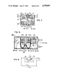
- FIG. 10 is a simplified, perspective diagram of paired accelerometers having their force-sensing axes parallel to an axis of angular vibration;
- FIG. 11 is a simplified, perspective diagram of paired accelerometers arranged back to back with their force-sensing axes normal to an axis of angular vibration;
- FIG. 12 is a simplified, perspective diagram of paired accelerometers arranged back to back with their force-sensing axes normal to the direction of linear vibration;
- FIG. 13 is a diagram similar to that of FIG. 3 used to illustrate the operation of the paired accelerometer arrangement of FIG. 10 in a three-axis-rate sensor;
- FIG. 14 is a diagram of a type similar to that of FIG. 3 illustrating the operation of the paired accelerometer of FIG. 11 in a three-axis-rate sensor;
- FIG. 15 is a diagram of the type similar to that of FIG. 3 illustrating the operation of the paired accelerometer arrangement of FIG. 12 in a three-axis-rate and force sensor;
- FIG. 16 is a side view of a mechanism for implementing the paired accelerometer arrangement of FIG. 10;
- FIG. 17 is a side view of a mechanism for implementing the paired accelerometer arrangement of FIG. 11;
- FIG. 18 is a side view of a mechanism for implementing the paired accelerometer arrangement of FIG. 12.
- FIG. 19 is a block diagram of a signal separating circuit of the type shown in FIG. 2 including the addition of a preprocessor circuit for summing and differencing the output signals of the accelerometers.
- the general equation for total acceleration measurable at a point mass moving in a rotating system is ##EQU1## where ⁇ is the angular rate or velocity vector of the system, F is the specific force vector and r is the instantaneous distance of the point mass from the center of rotation of the system.
- r ⁇ +l, wherein ⁇ is the instantaneous vector distance of the point mass from its center of revolution, and l the fixed distance of the element's center of revolution to the system center of rotation.
- the index b indicates differentiation with respect to the rotating body axes.
- an important feature of that invention is that it provides means for separating F x from q, F y from r, and F z from p, in such a manner that the undesirable terms are suppressed to a sufficiently low level so that the effect of the cross-product terms qp, qr and rp is substantially eliminated.
- FIG. 2 of the present application illustrates in block diagram form one nongyroscopic Inertial Measuring Unit (IMU) implementing the above-described principles of signal separation with respect to one channel, namely that of accelerometer A z , it being appreciated that the other two channels, for accelerators A x and A y , are similarly constructed.
- IMU Inertial Measuring Unit
- the unit illustrated in FIG. 2 includes three major subsystems, namely: a control pulse generator, generally designated 2; an electromechanical drive, generally designated 3, for rotating each of the accelerometers of the triad illustrated in FIG. 1; and an electronic signal-separation processor, generally designated 4.
- a control pulse generator generally designated 2
- an electromechanical drive generally designated 3
- an electronic signal-separation processor generally designated 4.
- the multivibrator controls a square wave generator 22 which generates squarewaves at a frequency f. These square waves are used as synchronizing pulses. They are applied to a reset-and-integrate control pulse generator 23 and to a sampling pulse generator 24, which generators are used to control the operation of processor 4, as will be described more particularly below.
- Synchronizing pulses from the square-wave generator 22 are also applied to a drive signal generator 31 within the electromechanical drive system 3.
- the output pulses from generator 31 drive the accelerometers of the assembly 32, such that the accelerometers are rotated about their respective axes at a predetermined frequency ( ⁇ ) equal to 2 ⁇ f.
- the accelerometer output a z is fed to the processor 4 for separating therefrom the specific force vector F z and angular rate vector p in such a manner so as to substantially suppress the undesirable components of signal a z in accordance with the Equations (3)-(5) and (6)-(8) discussed above.
- equation (5) is the pertinent one.
- processor 4 includes a multiplier or sign-switching circuit 41 for multiplying the introduced values a z by the zero mean periodic function "sgncos ⁇ t," outputting the product signal a z sgncos ⁇ t.
- This latter signal is fed to an integrating circuit 42 which integrates the product signal over the cyclic period T.
- the integrating circuit 42 is reset at the end of period T by the control pulse generator 23, but before being reset, it outputs its contents to a sample-and-hold circuit 43, which latter circuit is controlled by the sampling pulse generator 24.
- this processing of the accelerometer output signal a z causes the contents of the sample-and-hold circuit 43 to correspond to the angular rate component "p".
- the accelerometer output signal a z is also fed to a second channel within processor 4 including a second integrating circuit 44 which integrates that signal over the period T. Integrating circuit 44 is also reset at the end of period T by the control pulse generator 23, but just before being reset, it outputs its contents to another sample-and-hold circuit 45 controlled by the sampling pulse generator 24. It will be appreciated, from the previous discussion, that the contents of the sample-and-hold circuit 44 will correspond to the specific force vector F z .
- the invention of the present application utilizes vibrating accelerometers for generating the accelerometer output signals from which are derived the components of the specific force vector F and the components of the angular rate vector ⁇ while substantially suppressing the undesirable components of such signals.
- FIG. 3 which is similar to the diagram of FIG. 1 but includes vibrating accelerometers rather than rotating accelerometers.
- FIG. 3 thus illustrates a triad of accelerometers A x , A y , A z arranged to vibrate at an amplitude " ⁇ " and frequency " ⁇ " perpendicular to the (x,y), (y,z) and (x,z) planes, respectively, with the sensitive input axes aligned as shown in the x, y, z directions.
- FIGS. 4 through 9 Specific vibrating accelerometer mechanizations are illustrated in FIGS. 4 through 9, to be described below. These figures illustrate only one channel, namely that of accelerometer A z , wherein the accelerometer-sensitive axis for the specific force vector is the Z-axis, and the axis of vibration is the Y-axis, the sensitive axis for the angular rate vector being the X-axis.
- accelerometer A z vibrating along the Y-axis, measures the inertial specific force and angular rate of the moving body with respect to reference axes Z and X.
- the other two channels i.e., for accelerometers A x and A y , are similarly constructed and provide corresponding measurements for their respective axes.
- the frequency of vibration ( ⁇ ) of the accelerometers in all the below-described embodiments is 30-60 Hz, and the displacement during their vibratory motions is typically in the range of 0.25-3 mm.
- Equation (3)-(5) e.g., 2 ⁇ sin ⁇ t "and ⁇ (pq-r) cos ⁇ t; in Equation 3) do not even exist, thereby inherently permitting greatly improved overall performance.
- Equation 3 the orthogonal terms in Equations (3)-(5) (e.g., 2 ⁇ sin ⁇ t "and ⁇ (pq-r) cos ⁇ t; in Equation 3) do not even exist, thereby inherently permitting greatly improved overall performance.
- the accelerometer assembly illustrated in FIG. 4, therein generally designated 50 comprises an outer cylindrical housing 52 enclosing an accelerometer unit 54 containing an accelerometer proof mass 56.
- the accelerometer unit 54 is carried by a mounting plate 58 resiliently mounted within housing 52 by means of a resilient diaphragm 60, which diaphragm constrains the movement of the accelerometer unit 54 only to the Y-axis, this being the axis of vibration, and perpendicular to the Z-axis, which is the specific-force-vector-sensitive axis for the accelerometer assembly, as noted above.
- the driving means for vibrating the accelerometer unit 54 along the Y-axis comprises a permanent magnet 62 of cylindrical construction fixed within housing 52 at one end thereof and formed with a cylindrical air gap 64 coaxial with the Y-axis of vibration of the accelerometer assembly.
- the drive means further includes a driving coil 66 carried on a cylindrical bobbin 68 fixed to the accelerometer mounting plate 58 within the cylindrical air gap 64 and coaxial with the Y-axis of vibration.
- Driving coil 66 is adapted to receive sinusoidal driving current producing a force which causes the accelerometer unit 54, including its proof mass 56 and mounting plate 58, to move sinusoidally along the Y-axis of vibration as constrained by the spring force of diaphragm 60.
- the accelerometer assembly illustrated in FIG. 4 further includes pick-off means disposed within housing 52 and coupled to the accelerometer unit 54 and its mass 56 for measuring the rate of displacement thereof along the Y-axis of vibration.
- pick-off means may comprise another permanent magnet 70 (or an ironless field coil) and a pick-off coil 72 cooperable therewith at the other end of housing 52.
- Permanent magnet 70 is also of cylindrical construction, but of much smaller dimensions than the drive magnet 62, and is also formed with a cylindrical air gap 74, and the pick-off coil 72 is also carried on a cylindrical bobbin 76 secured to the accelerometer unit 54 so that the pick-off coil 72 is disposed within air gap 74 and is coaxial to the Y-axis of vibration of the accelerometer assembly.
- the accelerometer assembly illustrated in FIG. 4 further includes a first group of external terminals 77 connected by electrical leads (not shown) to the driving coil 66 for feeding in the driving current and the pick-off coil 76 measuring the motion of the accelerometer 54, and a second group of external terminals 78 connected by electrical leads (not shown) to internal terminals 79 carried by the accelerometer unit 54 for feeding the supply voltages and output signals to and from the accelerometer unit 54.
- the pick-off coil 72 which moves with the accelerometer unit 54, induces a voltage proportional to the velocity of the sinusoidal motion of the accelerometer unit 64, the measured velocity of motion along the Y-axis of vibration (namely y) being outputted via terminal 77.
- the signal outputted by the pick-off coil 72 constitutes this measured velocity (y) of the moving assembly, including the accelerometer unit 54.
- FIG. 5 illustrates how this measured velocity (y), outputted by the pick-off coil 72, is also used to enforce a closed-loop controlled motion of the accelerometer unit 54, by controlling the supply of the driving current to the driving coil 66.
- the latter motion is measured by the pick-off coil 72 in FIG. 4 and is fed, via lead 90, into another input terminal of the differential power amplifier 84.
- FIG. 5 is a negative feedback loop having a total loop gain L determined by the gain of amplifier 84 and the pick-off 72.
- the closed-loop drive system of FIG. 5 provides a well regulated and controlled sinusoidal linear velocity along the Y-axis.
- the high-gain, feedback drive system generating the required motion with a negligible nonlinear and phase distortion.
- the open-loop transfer function of the electrodynamic drive is given by:
- R c resistance of driving coil
- AKH is in the order of 10 5 ⁇ 10 6 .
- an accelerometer assembly 50 as illustrated in FIG. 4, including a closed-loop drive as illustrated in FIG. 5, would be applied for each of the three axes, with the outer housing 52 of the accelerometer assembly mounted to the vehicle (i.e., the moving body).
- the outer housing 52 of the accelerometer assembly 50 for each axis would be applied to the inner gimbal of the platform.
- the vibratory motion of the accelerometer assembly may cause reaction forces acting on the support of the outer housing 52.
- two vibrating assemblies such as shown at 50a and 50b in FIG. 6, may be mounted back to back, with one assembly including an accelerometer, as described above, vibrating in synchronism with, but in opposite direction to, the other assembly vibrating a counterbalancing mass dynamically balancing the accelerometer assembly.
- FIG. 7 illustrates a second type of vibrating accelerometer arrangement, namely, one in which the accelerometer is rotated by an electrical torque motor through a small angular oscillatory motion (e.g., a few degrees) which makes the vibratory motion almost rectilinear.
- the sensitive axis of the accelerometer is parallel to this axis of rotation.
- a suitable balancing mass is provided to dynamically balance the accelerometer during its oscillatory motion so that no external forces are imparted to the body to which the assembly is mounted.
- the accelerometer assembly illustrated in FIG. 7, therein generally designated 100 comprises an outer cylindrical housing 102 rotatably mounting a shaft 104 via rotary bearings 106 and 108.
- a disc or plate 110 which serves as a supporting member for supporting an accelerometer unit 112 having a proof mass 114.
- Disc 110 also carries a counterbalancing mass 116 on the opposite side of the disc.
- Disc 110 is driven through a small angular oscillatory motion by means of an electrical torque motor including a stator 118 fixed to housing 102 and a rotor 120 fixed to shaft 104.
- a pick-off rotor 122 is secured to the opposite end of shaft 104 and is disposed within a pick-off stator 124 secured to housing 102.
- the electrical connections may be the same as illustrated in FIG. 5, wherein the differential power amplifier 84 feeds the driving current to the conductors of the torque motor stator 118 to drive its rotor 120 and, thereby, the accelerometer 112 and counterbalancing mass 116 secured to the motor rotor 120, through a small angular oscillatory motion having an amplitude " ".
- This will cause the displacement y ⁇ r ⁇ , where "r” is the radius from the axis of rotation 130 of shaft 104 to the center of gravity of the accelerometer proof mass 114.
- the oscillatory movement of the accelerator 112 into and out of the paper plane is substantially linear along an axis perpendicular to the sensitive Z-axis of the accelerometer.
- r may be about 3 cm; the angular oscillatory motion may be a few degrees; and the amplitude of displacement of the accelerometer may be 0.25-3 mm.
- FIG. 7 has a number of advantages over that described above with respect to the FIGS. 4-6, including greater simplicity of mechanical parts, high precision of motion implementation, and substantially complete immunity to linear accelerations in all axes.
- FIG. 8 illustrates a third type of vibrating accelerometer assembly, namely, one using a tuning fork, which may be provided for each sensitive axis of the moving body in order to provide dynamic balancing of the forces, as well as important advantages to be described below.
- FIG. 9 illustrates a manner of connecting the vibrating accelerometer assembly of FIG. 8 so as to form an electromechanical oscillator for sustaining oscillations of the tuning-fork accelerometer assembly with but a small amount of input power, sufficient to replenish the energy loss due to friction.
- the vibrating accelerometer assembly therein generally designated 200, comprises an outer cylindrical housing 202 in which is mounted a tuning fork 204, including a pair of prongs 204a, 204b.
- the prongs extend parallel to the sensitive axis for the respective accelerometer assembly, this being the Z-axis in FIG. 8, and thereby perpendicularly to the axis of vibration of the accelerometer assembly, this being the Y-axis in FIG. 8.
- the tuning fork 204 is mounted within housing 202 by means of a mounting post 206 secured to an intermediate web 204c of the tuning fork.
- Housing 202 further includes another post 208 aligned with post 206 but spaced from it and also from web 204c of the tuning fork 204.
- Post 208 is used for mounting, on one side, a permanent magnet 210 cooperable with a drive coil 212, and, on the other side, a permanent magnet 214 cooperable with a pick-off coil 216.
- the two permanent magnets 210 and 214 are of cylindrical configuration and include cylindrical air gaps within which are disposed their respective drive coil 212 and pick-off coil 216, each of the latter coils being carried on cylindrical bobbins 218 and 220 secured to the inner faces of the two prongs 204b and 204a.
- an accelerometer unit 224 having a mass 226.
- an accelerometer unit 224 having a mass 226.
- another mass 228 is secured to the outer face of prong 204a of the tuning fork another mass 228 to provide a counterbalance for accelerometer unit 224 and its mass 226.
- the electrical connections to the driving coil 212 and pick-off coil 216, as well as to the accelerometer unit 224, are provided by terminals 230 and 232 extending externally of housing 202 and terminals 234 internally of the housing and connected to the accelerometer unit 224.
- the tuning fork 204 in FIG. 8 vibrates at this natural frequency, and thereby causes the accelerometer unit 224 and its mass 226 on prong 204b to move in synchronism with, but in opposite directions to, the counterbalancing mass 228 on prong 204a.
- this support would be the moving body itself in a strapdown application, and the inner gimbal of a platform in a stable gimballed platform application.
- the arrangement illustrated in FIG. 8 thus provides a high degree of dynamic balancing.
- the vibrating accelerometer assembly 200 illustrated in FIG. 8 may be connected to form an electromechanical oscillator, as illustrated in FIG. 9.
- the signal across the pick-off coil 216 is fed to an amplifier 240, the output of which is connected to the input of the driving coil 212.
- the amplifier 240 is of a polarity to reinforce any initial displacement of the prongs 204a, 204b of the tuning fork 204.
- the system operates as an electromechanical oscillator having a frequency determined by the natural frequency of the tuning fork. This natural frequency can be used to synchronize precisely the frequency of the free-running multivibrator 21 in FIG. 2.
- amplifier 240 is of the nonlinear type, such as including a saturation device, so as to force the complete electromechanical oscillator to stabilize at a finite amplitude.
- the tuning-fork accelerometer assembly arrangement illustrated in FIGS. 8 and 9 provides a balancing dynamical system because of the countermoving masses, and requires but a small amount of power for the driving coil 212, merely to replenish the energy loss due to friction.
- the assembly being a sharply tuned oscillator, rejects mechanical disturbances in the axis of vibration (Y-axis in FIG. 8) unless they are exactly at the resonant frequency.
- the structure is inherently rigid in the accelerometer-sensitive axis, namely the Z-axis.
- the assembly operates at the natural frequency and synchronizes the multivibrator 21 of the control pulse generator 2 in FIG. 2, there are no phase lags involved between cos ⁇ t and sgncos ⁇ t.
- the accelerometer assembly is extremely simple and can be constructed at low cost.
- FIGS. 10-12 Simplified illustrations of three arrangements of paired accelerometers are provided in FIGS. 10-12.
- a significant advantage of utilizing accelerometers arranged in pairs, as shown in FIGS. 10-12, is that the noise present in both the force and the rate channel of FIG. 2 is increased only by the square root of two while the effective force and rate signals are doubled, thus providing an effective signal to noise increase of a square root of two.
- common acceleration disturbances in the rate channel due to external forces that may result from vehicular and mechanization sources are substantially cancelled in this type of arrangement.
- the first arrangement of paired accelerometers is illustrated in FIG. 10 where a pair of accelerometers 300 and 302 are mounted on an angularly rotating base 304 which vibrates about the Z-axis 306 as indicated by the arrows 308.
- the force-sensing axes A z 1 and A z 2 of the accelerometers 300 and 302 are aligned so as to be parallel to the Z-axis 306 about which the support 304 vibrates. Since the arrangement in FIG. 10 includes a pair of accelerometers with their force-sensing axes A z 1 and A z 2 parallel to the vibration axis 306, this arrangement will hereinafter be referred to as the PAPVA arrangement.
- the second arrangement of paired accelerometers is shown in FIG. 11 where two accelerometers 310 and 312 are mounted on a support 314 which vibrates angularly about the Z-axis indicated at 318 as suggested by the arrows 316.
- the accelerometers 310 and 312 are secured to the support 314 in a back-to-back arrangement such that the force-sensing axes A x 1 and A x 2 are parallel, but opposite in direction, and are normal to the axis 318 of angular vibration.
- This arrangement will hereinafter be termed the PANVA arrangement to denote a pair of accelerometers subject to angular motion with their force-sensing axis normal to the axis of vibration or angular motion.
- the third arrangement is illustrated in FIG. 12 where a pair of accelerometers 320 and 322 are arranged back to back with their force-sensing axes A y 1 and A y 2 located in parallel but opposite directions.
- the accelerometers 320 and 322 are caused to vibrate in a linear direction along the X-axis, as indicated by arrows 324 and 326.
- this arrangement will hereinafter be referred to as PLNVA due to the fact that it is an arrangement of paired accelerometers caused to vibrate in a linear manner along a vibration axis which is normal to the force-sensing axis.
- FIGS. 13-15 correspond to the PAPVA, PANVA and PLNVA arrangements of FIGS. 10-12, respectively, and provide a conceptual illustration of how the paired accelerometers can be arranged in triads.
- the accelerometers are denoted by their force-sensing axes A x 1 , A x 2 , A y 1 , A y 2 , A z 1 , and A z 2 and prove force sensing and angular rate sensing along and about the orthogonal axes X, Y and Z.
- the arrangements shown in FIGS. 13-15 are suitable for use in an inertial reference system that can in turn be used in an Inertial Navigation System.
- the accelerometer pairs are vibrated at an angular constant frequency ⁇ and constant angular amplitudes ⁇ M .
- the principle of force and angular rate signal separation is substantially the same as illustrated in FIG. 2.
- the accelerometer outputs contain the same basic information for angular rotation ⁇ and force F, although the actual signal content is somewhat different.
- the accelerometer signals are preprocessed as sums and differences as shown in FIG. 19 in accordance with the following matrix equation: ##EQU13## Assuming again F and ⁇ are substantially constant in the interval T, all time derivatives vanish in Equations (11)-(16). Substituting accordingly into Equation (17) and expanding:
- FIG. 14 six accelerometers A x 1 , A x 2 , A y 1 , A y 2 , A z 1 and A z 2 are used in the PANVA mechanization. Again, the accelerometer pairs are vibrated at angular frequency ⁇ and angular amplitude ⁇ .
- the accelerometer outputs contain ⁇ and F information as before but with different additional dynamic terms.
- the basic principle of signal separation is not changed. This mechanization also has the advantage of essentially perfect vehicular noise rejection.
- the instantaneous distance of each accelerometer from the vehicular center of rotation is: ##EQU17## Since, in this mechanization, the accelerometer input axes change direction with respect to the body axes, the sensed components are modulated. For example, the input axis varies in accordance with ⁇ : [Cos ⁇ i, O ⁇ j, Sin ⁇ k].
- Equation (1) the actual accelerometer pair outputs for a x 1 and a x 2 can be represented by: ##EQU19## Similar equations for a y 1 , a y 2 , a z 1 and a z 2 result from this substitution.
- Equation (28) Substituting Equations (28) and (29) along with similar equations for a y 1 , a y 2 , a z 1 and a z 2 into Equation (30) and assuming F and ⁇ constant throughout T, results in:
- Equation (31) the equations for the angular rate component of the accelerations, such as Equation (31), and the equations for the force component of the accelerations, such as Equations (32), into Equations (22) and (23) results in: ##EQU21##
- the PLNVA mechanisms shown in FIGS. 12 and 15 are similar to PANVA mechanisms except that motion of the accelerometers 320 and 322 is linear.
- the instantaneous distance to the vehicular center of rotation is: ##EQU22##
- Equation (36) Substituting Equation (36) below into Equation (1) and expanding, the following equations for a x 1 and a x 2 result: ##EQU23## with similar equations for a y 1 , a y 2 , a z 1 and a z 2 also resulting from the substitution.
- Equation (36) Substituting Equations (36) and (37) along with the equations for a y 1 , a y 2 , a z 1 and a z 2 into Equation (30), and assuming F and ⁇ are constant throughout T, results in:
- FIGS. 16 through 18 are illustrated apparatus for implementing the PAPVA mechanization of FIG. 10, the PANVA mechanization of FIG. 11, and the PLNVA mechanization of FIG. 12, respectively.
- the apparatus for mechanizing the PAPVA mechanism is shown in FIG. 16 and includes a housing 330 having a pair of input/output plugs 332 and 334. Secured to the housing 330 by means of a pair of bearings or flexible joints 336 and 338 is a shaft 340.
- the paired accelerometers 300 and 302 are mounted on the accelerometer support frame or member 304 which in turn is secured to the shaft 340 for rotation therewith.
- Rotational vibration of the shaft 340 is provided by a motor that includes a rotor 342 connected to the shaft 340 and a stator 344 attached to the housing 330.
- Signals providing either position or velocity information for a feedback signal to a drive servo that would control the amplitude ⁇ of the shaft 340 vibration can be obtained by the pick-off arrangement indicated generally at 346.
- FIG. 17 An apparatus for implementing the PANVA mechanization is provided in FIG. 17, wherein the accelerometers 310 and 312 are mounted on the support 314 which in turn is secured to a shaft 348.
- the shaft 348 is rotatably secured within a housing 350 by means of a pair of bearings or flexible joints 352 and 354.
- Angular vibration of the shaft 348 and, hence, the accelerometers 310 and 312 is provided by an electric motor which includes a rotor 356 secured to the shaft 348 and a stator 358 secured to the housing 350.
- Signals of the motion of the accelerometers 310 and 312 can be obtained by the pick-off arrangement indicated generally at 360 to provide negative feedback for a drive servo controlling the amplitude ⁇ of the shaft 348 vibration.
- FIG. 18 An arrangement for implementing the PLNVA mechanization of FIG. 12 is illustrated in FIG. 18.
- linear translation of the accelerometers 320 and 322 along the axes 324 and 326, as shown in FIG. 12, is provided by a mechanism that includes a support frame 362 that holds the accelerometers 320 and 322 which is secured to a housing 364 by means of a pair of flexures 366 and 368.
- Abutting the lower portion of the accelerometer support frame 362 is a linkage element 370 that in turn is secured to a shaft 372.
- the shaft 372 is rotatably secured within the housing 364 by means of a pair of bearings or flexible joints 374 and 376.
- An electric motor including a rotor 378 attached to the shaft 372 and a stator 380 attached to the housing 364 will cause the shaft 372 to rotate or vibrate back and forth through a very limited angular rotation.
- the linkage element 370 will cause the accelerometers 320 and 322 to move in directions essentially normal to the force sensing-axes A y 1 and A y .sup. 2.
- substantially linear movement of the accelerometers 320 and 322 can be achieved in a direction normal to their force-sensing axes by using the mechanism of FIG. 18.
- Signals representing angular position or velocity of the shaft for use by a drive servo can be obtained by means of the pick-off arrangement indicated generally at 382.
- FIG. 19 The preferred embodiment of a signal processor for separating the force signals F from the angular rate signals ⁇ for the paired accelerometer mechanizations of FIGS. 10 through 13 is illustrated in FIG. 19.
- the basic operation of the processor circuit shown in FIG. 19 is the same as the signal separation circuit of FIG. 2.
- the control pulse generator 2 is the same as shown in FIG. 2 with a line 384 connecting the square wave generator 22, as shown in FIG. 2, to the drive signal generator 31.
- the output of the reset and integrate control pulse generator 23 is transmitted on a line 386 from the control pulse generator 2, and the output of the sampling and pulse generator 24 is transmitted on a line 388.
- Accelerometer output signals a z 1 and a z 2 are output from the accelerometer assemblies 390 and 392 on a pair of lines 394 and 396, respectively.
- a force channel circuit 402 includes the integrating circuit 44 and the sample-and-hold circuit 45 of the electronic signal separation processor 4 of FIG. 2, with the signals on lines 386 and 388 being applied to the integrating circuit 44 and the sample-and-hold circuit 45 as shown in FIG. 2.
- an angular rate channel circuit 404 includes the integrating circuit 42 and the sample-and-hold circuit 43 of FIG. 2, as well as the sign switching or multiplying circuit 41. The signals on lines 386 and 388 are applied to the integrating circuit 42 and the sample-and-hold circuit 43, as well as the pulse signal on line 384 in the same manner as shown in FIG. 2.
- One of the key advantages of the paired accelerometer mechanization is the ability to use sum and difference techniques to separate those signals which pertain primarily to translational motion from the signals which pertain primarily to angular motions.
- To be able to cancel linear specific force signals that are output from paired accelerometers it is necessary that the force-sensing axes be nearly as parallel as possible and that the effective centers of mass be close together as well.
- the force-sensing axes of the accelerometers are in the same or opposite directions is a matter of convenience in designing the mounting of the accelerometers. In either case, the separation process is made possible by designing the mechanism that produces the vibratory motion so that the driven velocity factors are at all times equal and opposite when measured in the frame of reference of the housing.
- a preprocessor circuit for performing the sum and difference functions is illustrated in the dashed line 406 of FIG. 19.
- the preseparation or preprocessor circuit 406 includes two summing junctions 408 and 410.
- the particular preprocessing circuit 406 shown in FIG. 9 is utilized for mechanizations where the force-sensing axes are in the same direction, such as in the PAPVA mechanization shown in FIG. 10 and, as such, implements the logic of Equation (17).
- the summing junction 408 acts to provide a signal to the force channel 402 that represents the sum of the accelerometer signals on lines 394 and 396.
- the summing junction 410 provides a signal to the angular rate channel 404 that represents the difference between the accelerometer signals on lines 394 and 396. It is assumed that the nonrotational specific force signals will be substantially equal on lines 394 and 396 so that the summed signal on line 412 will, in effect, provide twice the sensitivity for the specific force being measured by accelerometers along the force-sensing axes. Likewise, the difference signal on line 414 will be substantially free of components representing specific force. Conversely, a purely rotational motion will produce two sinusoidal Coriolis accelerations along the force-sensitive axes of the accelerometers with a phase difference of 180°.
- the same principles apply except, of course, the signs of the signals are reversed.
- the summing junction 408 would difference the acceleration signals on lines 394 and 396 and the summing junction 410 would add the signals on lines 394 and 396 conforming generally to the relations expressed in Equation (30).
- the summed signal from summing junction 410 will contain angular rate information only while the difference signal from summing junction 408 contains specific force information only. Therefore, it may be seen that the preprocessor 406 has the effect of separating the specific force signal from the angular rate signal before the signals are applied to the force channel 402 and the angular rate channel 404.
- a further advantage of the circuit arrangement shown in FIG. 19 is that the sum and difference techniques provided by the preprocessor 406 can be used to facilitate the scaling of the signals applied to the force channel 402 and the angular rate channel 404.
- Scaling is illustrated by means of a pair of scaling amplifiers 416 and 418.
- the scaling amplifiers 416 and 418 can be used to scale the level of signals being applied to the force channel 402 and the angular rate channel 404 without concern for the magnitude of the signal output from the accelerometers. This is particularly important when one considers that the amplitudes of the signals representing specific force F z may be up to 100 times greater than the signal amplitudes relating to angular rate ⁇ .
- the values of the amplifier gain constants K F and K.sub. ⁇ can be adjusted to the expected signal amplitudes on lines 412 and 414 to permit the maximum resolution of the signals without overranging the circuits 402 and 404.
- Inertial Navigation System gains K F and K.sub. ⁇ can be switched to increase sensitivity and, hence, to improve resolution during the navigation system adjustment process.
- F z and p have been chosen by way of illustration of one of the component pairs of F and ⁇ . Identical consideration pertain to F x and q and F y and r.
- accelerometer noise present in the output of the angular rate channel 404 is a principal factor in the accuracy of an Inertial Navigation System using accelerometers to determine angular rate.
- the effect of accelerometer noise for a given accelerometer level of noise is inversely proportional to the vibration amplitude. It has been found, for example, utilizing the QA-2000 accelerometer commercially available from Sundstrand Data Control, Inc., the positional error is about two nautical miles per hour for a vibration amplitude of approximately 1.25 mm.
Landscapes
- Physics & Mathematics (AREA)
- Engineering & Computer Science (AREA)
- General Physics & Mathematics (AREA)
- Radar, Positioning & Navigation (AREA)
- Remote Sensing (AREA)
- Gyroscopes (AREA)
Abstract
Description
n=n.sub.d +n.sub.v +n.sub.r
F=BlJ≃Blu/R.sub.c
y=h.sub.o V.sub.i +h.sub.1 V.sub.i.sup.2
δ=δ.sub.M S ωt (7)
δ=ωδ.sub.M Cωt (8)
Sin δ≃δ=δ.sub.M Sωt (9)
Cos δ≃11/2δ.sub.M.sup.2 S.sup.2 ωt (10)
L δ.sub.M ρ/2
a.sub.x.sup.q =2ωρCωt(q+δ.sub.M Sωt·r)+ρSωt·pr+2Lqp--Lδ.sub.M.sup.2 S.sup.2 ωtqp-2ωρCωt(1/2)δ.sub.M.sup.2 S.sup.2 ωt·q (18)
a.sub.y.sup.r =2ωρCωt(r+δ.sub.M Sωt·p)+ρSωtpq+2Lrq--Lδ.sub.M.sup.2 S.sup.2 ωtrq-2ωρCωt(1/2)δ.sub.M.sup.2 S.sup.2 ωt·r (19)
a.sub.z.sup.p =2ωρCωt(p+δ.sub.M Sωt·q)+ρSωtqr+2Lpr--Lδ.sub.M.sup.2 S.sup.2 ωtpr-2ωρCωt(1/2)δ.sub.M.sup.2 S.sup.2 ωt·p (20) ##EQU14## Thus, two advantages are obtained through the paired mechanization, all specific force components are removed from the acceleration signals in Equations (18)-(20) and all angular rate components are removed from signals in Equation (21). This significantly improves the decoupling of F from Ω. Common mode noise terms due to vehicle noise are also removed from the Ω channel as can be seen from Equations (18)-(20). To obtain estimates of p, q and r as defined by Equation (22) below, ##EQU15## p, q and r in Equations (18)-(20) are substituted into Equation (22), and to obtain an estimate of F.sub.x, F.sub.y and F.sub.z as defined by Equation (23) below, F.sub.x, F.sub.y and F.sub.z are substituted in Equation (21) into Equation (23). The corresponding results are: ##EQU16## Thus, p, q and r are determined precisely except for a contant known scale factor and F.sub.x, F.sub.y and F.sub.z are the same as determined before.
a.sub.x.sup.q =2ωρCωt·q+ρSωt·pr-2L(q.sup.2 +r.sup.2)+(1/2)
δ.sub.M.sup.2 S.sup.2 ωt[2r.sup.2 L-4L(p.sup.2 +q.sup.2)]--2L·ω.sup.2 δ.sub.M.sup.2 C.sup.2 ωt (31)
a.sub.x.sup.F.sbsp.x =F.sub.x +l.sub.z pr+δ.sub.M Sωt[F.sub.z -1.sub.z (p.sup.2 +q.sup.2)]+(1/2)
δ.sub.M.sup.2 S.sup.2 ωt[-F.sub.x -l.sub.z ·pr](32)
a.sub.x.sup.q =2ωρCωt·q+ρSωt·pr-2L(q.sup.2 +r.sup.2) (38)
a.sub.y.sup.r =2ωρCωt·r+ρSωt·pq-2L(p.sup.2 +r.sup.2) (39)
a.sub.z.sup.p =2ωρCωt·p+ρSωt·qr-2L(p.sup.2 +q.sup.2) (40)
a.sub.x.sup.F.sbsp.x =F.sub.x +1.sub.z pr (41)
a.sub.y.sup.F.sbsp.y =F.sub.y +1.sub.x pq (42)
a.sub.z.sup.F.sbsp.z =F.sub.z +1.sub.z qr (43)
Claims (62)
Priority Applications (1)
| Application Number | Priority Date | Filing Date | Title |
|---|---|---|---|
| US06/737,919 US4590801A (en) | 1983-09-02 | 1985-05-28 | Apparatus for measuring inertial specific force and angular rate of a moving body |
Applications Claiming Priority (2)
| Application Number | Priority Date | Filing Date | Title |
|---|---|---|---|
| US52877683A | 1983-09-02 | 1983-09-02 | |
| US06/737,919 US4590801A (en) | 1983-09-02 | 1985-05-28 | Apparatus for measuring inertial specific force and angular rate of a moving body |
Related Parent Applications (1)
| Application Number | Title | Priority Date | Filing Date |
|---|---|---|---|
| US52877683A Continuation | 1983-09-02 | 1983-09-02 |
Publications (1)
| Publication Number | Publication Date |
|---|---|
| US4590801A true US4590801A (en) | 1986-05-27 |
Family
ID=27062821
Family Applications (1)
| Application Number | Title | Priority Date | Filing Date |
|---|---|---|---|
| US06/737,919 Expired - Lifetime US4590801A (en) | 1983-09-02 | 1985-05-28 | Apparatus for measuring inertial specific force and angular rate of a moving body |
Country Status (1)
| Country | Link |
|---|---|
| US (1) | US4590801A (en) |
Cited By (95)
| Publication number | Priority date | Publication date | Assignee | Title |
|---|---|---|---|---|
| WO1987002468A1 (en) * | 1985-10-21 | 1987-04-23 | Sundstrand Data Control, Inc. | Synchronous fm digital detector |
| WO1987002469A1 (en) * | 1985-10-21 | 1987-04-23 | Sundstrand Data Control, Inc. | Signal processor for inertial measurement using coriolis force sensing accelerometer arrangements |
| US4712426A (en) * | 1985-10-21 | 1987-12-15 | Sundstrand Data Control, Inc. | Synchronous FM digital detector |
| US4744248A (en) * | 1985-07-25 | 1988-05-17 | Litton Systems, Inc. | Vibrating accelerometer-multisensor |
| US4744249A (en) * | 1985-07-25 | 1988-05-17 | Litton Systems, Inc. | Vibrating accelerometer-multisensor |
| US4761743A (en) * | 1985-12-02 | 1988-08-02 | The Singer Company | Dynamic system analysis in a vibrating beam accelerometer |
| US4782700A (en) * | 1987-07-17 | 1988-11-08 | Sundstrand Data Control, Inc. | Frame assembly and dither drive for a coriolis rate sensor |
| US4791815A (en) * | 1986-04-11 | 1988-12-20 | Matsushita Electric Industrial Co., Ltd. | Cyclically driven gyro and adjusting system therefor |
| US4792676A (en) * | 1985-10-22 | 1988-12-20 | Kabushiki Kaisha Tokyo Keiki | Gyro apparatus with a vibration portion |
| US4799385A (en) * | 1987-07-10 | 1989-01-24 | Sundstrand Data Control, Inc. | Angular rate sensor with phase shift correction |
| US4811602A (en) * | 1987-07-17 | 1989-03-14 | Sundstrand Data Control, Inc. | Frame assembly and dither drive for a coriolis rate sensor |
| US4821572A (en) * | 1987-11-25 | 1989-04-18 | Sundstrand Data Control, Inc. | Multi axis angular rate sensor having a single dither axis |
| US4839838A (en) * | 1987-03-30 | 1989-06-13 | Labiche Mitchell | Spatial input apparatus |
| US4848156A (en) * | 1987-07-17 | 1989-07-18 | Sundstrand Data Control, Inc. | Frame assembly and dither drive for a coriolis rate sensor |
| US4896268A (en) * | 1987-11-25 | 1990-01-23 | Sundstrand Data Control, Inc. | Apparatus and method for processing the output signals of a coriolis rate sensor |
| US4908767A (en) * | 1987-01-16 | 1990-03-13 | Valentine Research, Inc. | Acceleration measuring system |
| US5168756A (en) * | 1991-02-08 | 1992-12-08 | Sundstrand Corporation | Dithering coriolis rate and acceleration sensor utilizing a permanent magnet |
| US5243278A (en) * | 1991-02-08 | 1993-09-07 | Sundstrand Corporation | Differential angular velocity sensor that is sensitive in only one degree of freedom |
| US5241861A (en) * | 1991-02-08 | 1993-09-07 | Sundstrand Corporation | Micromachined rate and acceleration sensor |
| US5327770A (en) * | 1991-06-10 | 1994-07-12 | Infrared Engineering Limited | Apparatus for sampling a material travelling past a sampling region |
| US5331852A (en) * | 1991-09-11 | 1994-07-26 | The Charles Stark Draper Laboratory, Inc. | Electromagnetic rebalanced micromechanical transducer |
| US5331853A (en) * | 1991-02-08 | 1994-07-26 | Alliedsignal Inc. | Micromachined rate and acceleration sensor |
| US5349855A (en) * | 1992-04-07 | 1994-09-27 | The Charles Stark Draper Laboratory, Inc. | Comb drive micromechanical tuning fork gyro |
| US5357817A (en) * | 1990-04-19 | 1994-10-25 | Charles Stark Draper Laboratory, Inc. | Wide bandwidth stable member without angular accelerometers |
| US5383363A (en) * | 1993-02-10 | 1995-01-24 | Ford Motor Company | Inertial measurement unit providing linear and angular outputs using only fixed linear accelerometer sensors |
| US5385047A (en) * | 1992-07-16 | 1995-01-31 | Robert Bosch Gmbh | Angular speed measuring device |
| US5388458A (en) * | 1992-11-24 | 1995-02-14 | The Charles Stark Draper Laboratory, Inc. | Quartz resonant gyroscope or quartz resonant tuning fork gyroscope |
| US5396797A (en) * | 1991-02-08 | 1995-03-14 | Alliedsignal Inc. | Triaxial angular rate and acceleration sensor |
| US5408119A (en) * | 1990-10-17 | 1995-04-18 | The Charles Stark Draper Laboratory, Inc. | Monolithic micromechanical vibrating string accelerometer with trimmable resonant frequency |
| US5408879A (en) * | 1992-02-11 | 1995-04-25 | Fokker Aircraft B.V. | Assembly of linear accelerometers mounted on a rigid body remote from the center of mass measuring three dimensional movements |
| US5408877A (en) * | 1992-03-16 | 1995-04-25 | The Charles Stark Draper Laboratory, Inc. | Micromechanical gyroscopic transducer with improved drive and sense capabilities |
| US5430342A (en) * | 1993-04-27 | 1995-07-04 | Watson Industries, Inc. | Single bar type vibrating element angular rate sensor system |
| US5473945A (en) * | 1990-02-14 | 1995-12-12 | The Charles Stark Draper Laboratory, Inc. | Micromechanical angular accelerometer with auxiliary linear accelerometer |
| US5481914A (en) * | 1994-03-28 | 1996-01-09 | The Charles Stark Draper Laboratory, Inc. | Electronics for coriolis force and other sensors |
| US5535902A (en) * | 1993-02-10 | 1996-07-16 | The Charles Stark Draper Laboratory, Inc. | Gimballed vibrating wheel gyroscope |
| US5581035A (en) * | 1994-08-29 | 1996-12-03 | The Charles Stark Draper Laboratory, Inc. | Micromechanical sensor with a guard band electrode |
| US5597954A (en) * | 1994-10-04 | 1997-01-28 | Murata Manufacturing Co., Ltd. | Bearing sensor and bearing-distance sensor |
| US5605598A (en) * | 1990-10-17 | 1997-02-25 | The Charles Stark Draper Laboratory Inc. | Monolithic micromechanical vibrating beam accelerometer with trimmable resonant frequency |
| US5635639A (en) * | 1991-09-11 | 1997-06-03 | The Charles Stark Draper Laboratory, Inc. | Micromechanical tuning fork angular rate sensor |
| US5646348A (en) * | 1994-08-29 | 1997-07-08 | The Charles Stark Draper Laboratory, Inc. | Micromechanical sensor with a guard band electrode and fabrication technique therefor |
| US5650568A (en) * | 1993-02-10 | 1997-07-22 | The Charles Stark Draper Laboratory, Inc. | Gimballed vibrating wheel gyroscope having strain relief features |
| US5668318A (en) * | 1995-02-21 | 1997-09-16 | Wacoh Corporation | Angular velocity sensor |
| US5691472A (en) * | 1995-05-30 | 1997-11-25 | Alliedsignal, Inc. | Non-gimballed angular rate sensor |
| US5703292A (en) * | 1994-03-28 | 1997-12-30 | The Charles Stark Draper Laboratory, Inc. | Sensor having an off-frequency drive scheme and a sense bias generator utilizing tuned circuits |
| US5717140A (en) * | 1995-05-30 | 1998-02-10 | Alliedsignal, Inc. | Angular rate sensor electronic balance |
| US5723790A (en) * | 1995-02-27 | 1998-03-03 | Andersson; Gert | Monocrystalline accelerometer and angular rate sensor and methods for making and using same |
| US5725729A (en) * | 1994-09-26 | 1998-03-10 | The Charles Stark Draper Laboratory, Inc. | Process for micromechanical fabrication |
| US5767405A (en) * | 1992-04-07 | 1998-06-16 | The Charles Stark Draper Laboratory, Inc. | Comb-drive micromechanical tuning fork gyroscope with piezoelectric readout |
| US5783973A (en) * | 1997-02-24 | 1998-07-21 | The Charles Stark Draper Laboratory, Inc. | Temperature insensitive silicon oscillator and precision voltage reference formed therefrom |
| US5817942A (en) * | 1996-02-28 | 1998-10-06 | The Charles Stark Draper Laboratory, Inc. | Capacitive in-plane accelerometer |
| US5866816A (en) * | 1995-05-30 | 1999-02-02 | Alliedsignal Inc. | Angular rate sensor misalignment correction |
| US5892153A (en) * | 1996-11-21 | 1999-04-06 | The Charles Stark Draper Laboratory, Inc. | Guard bands which control out-of-plane sensitivities in tuning fork gyroscopes and other sensors |
| US5905201A (en) * | 1997-10-28 | 1999-05-18 | Alliedsignal Inc. | Micromachined rate and acceleration sensor and method |
| US5911156A (en) * | 1997-02-24 | 1999-06-08 | The Charles Stark Draper Laboratory, Inc. | Split electrode to minimize charge transients, motor amplitude mismatch errors, and sensitivity to vertical translation in tuning fork gyros and other devices |
| US5952574A (en) * | 1997-04-29 | 1999-09-14 | The Charles Stark Draper Laboratory, Inc. | Trenches to reduce charging effects and to control out-of-plane sensitivities in tuning fork gyroscopes and other sensors |
| US5978972A (en) * | 1996-06-14 | 1999-11-09 | Johns Hopkins University | Helmet system including at least three accelerometers and mass memory and method for recording in real-time orthogonal acceleration data of a head |
| US5983718A (en) * | 1997-07-14 | 1999-11-16 | Litton Systems, Inc. | Signal processing system for inertial sensor |
| US6003371A (en) * | 1995-02-21 | 1999-12-21 | Wacoh Corporation | Angular velocity sensor |
| US6128955A (en) * | 1999-07-09 | 2000-10-10 | Mimura; Nobuharu | Method for measuring 6 degrees of freedom motion and device therefor |
| US6636819B1 (en) | 1999-10-05 | 2003-10-21 | L-3 Communications Corporation | Method for improving the performance of micromachined devices |
| US20040035206A1 (en) * | 2002-03-26 | 2004-02-26 | Ward Paul A. | Microelectromechanical sensors having reduced signal bias errors and methods of manufacturing the same |
| US20040083812A1 (en) * | 2002-11-04 | 2004-05-06 | Toshihiko Ichinose | Z-axis vibration gyroscope |
| US6873931B1 (en) | 2000-10-10 | 2005-03-29 | Csi Technology, Inc. | Accelerometer based angular position sensor |
| US20050177335A1 (en) * | 2000-10-11 | 2005-08-11 | Riddell, Inc. | System and method for measuring the linear and rotational acceleration of a body part |
| US20050177929A1 (en) * | 2000-10-11 | 2005-08-18 | Greenwald Richard M. | Power management of a system for measuring the acceleration of a body part |
| US20060074338A1 (en) * | 2000-10-11 | 2006-04-06 | Greenwald Richard M | System for monitoring a physiological parameter of players engaged in a sporting activity |
| US7066004B1 (en) * | 2004-09-02 | 2006-06-27 | Sandia Corporation | Inertial measurement unit using rotatable MEMS sensors |
| US20060191337A1 (en) * | 2005-02-25 | 2006-08-31 | Askoll Holding S.R.I. | Detecting device of unbalance conditions particularly for washing machines and similar household appliances, activated by a synchronous electric motor |
| US20070153631A1 (en) * | 2005-12-29 | 2007-07-05 | Jean-Paul Menard | Six-component seismic data acquisition system |
| US20070177316A1 (en) * | 2004-03-12 | 2007-08-02 | Hotelling Steven P | Dual axis vibration rate gyroscope |
| US20070240486A1 (en) * | 2005-03-04 | 2007-10-18 | Moore Robert H | Inertial measurement system and method with bias cancellation |
| EP1859285A2 (en) * | 2005-03-04 | 2007-11-28 | Custom Sensors & Technologies, Inc. | Inertial measurement system and method with sensor bias cancellation |
| WO2007147896A1 (en) * | 2006-06-23 | 2007-12-27 | Thales | Inertial measurement unit with enhanced acceleration withstand capability |
| US20080196499A1 (en) * | 2007-02-21 | 2008-08-21 | Freescale Semiconductor, Inc. | Multiple axis transducer with multiple sensing range capability |
| US20080202237A1 (en) * | 2007-02-28 | 2008-08-28 | Dirk Hammerschmidt | Sensor And Method For Sensing The Linear Acceleration And An Angular Velocity |
| WO2007111978A3 (en) * | 2006-03-24 | 2008-08-28 | Custom Sensors & Technologies | Inertial measurement system and method with bias cancellation |
| US20080276706A1 (en) * | 2004-09-27 | 2008-11-13 | Conti Temic Microelectronic Gmbh | Rotation Speed Sensor |
| US20090288485A1 (en) * | 2008-05-22 | 2009-11-26 | Rosemount Aerospace Inc. | High bandwidth inertial measurement unit |
| US20100005884A1 (en) * | 2008-07-09 | 2010-01-14 | Weinberg Marc S | High Performance Sensors and Methods for Forming the Same |
| US20100096148A1 (en) * | 2008-10-21 | 2010-04-22 | Agatec | Independent position sensor and a system to determine the position of a tool on a works machine using position sensors |
| US20100122576A1 (en) * | 2008-11-17 | 2010-05-20 | Johannes Classen | Rotation rate sensor |
| US20120145476A1 (en) * | 2010-12-13 | 2012-06-14 | Masahiro Kamata | Seismic source, system, and method |
| US20140135666A1 (en) * | 2012-11-14 | 2014-05-15 | Zoll Medical Corporation | Chest Compression Monitor with Rotational Sensing of Compressions for Discrimination of CPR Movement from Non-CPR Movement |
| US20160003863A1 (en) * | 2014-07-02 | 2016-01-07 | Merlin Technology, Inc. | Mechanical shock resistant mems accelerometer arrangement, associated method, apparatus and system |
| US20170108336A1 (en) * | 2014-06-02 | 2017-04-20 | Motion Engine Inc. | Multi-mass mems motion sensor |
| US20190292734A1 (en) * | 2018-03-26 | 2019-09-26 | Roadtec, Inc. | Method and apparatus for avoiding or ameliorating cavitation in an asphalt cement fluid circuit |
| WO2020058941A1 (en) * | 2018-09-20 | 2020-03-26 | Thales Canada Inc. | Stationary state determination, speed measurements |
| US10768065B2 (en) | 2014-04-10 | 2020-09-08 | Mei Micro, Inc. | MEMS pressure sensor |
| US10945601B2 (en) | 2000-10-11 | 2021-03-16 | Riddell, Inc. | System and method for evaluating and providing treatment to sports participants |
| US10952671B2 (en) | 2000-10-11 | 2021-03-23 | Riddell, Inc. | System for monitoring a physiological parameter of players engaged in a sporting activity |
| US10969399B1 (en) | 2014-07-17 | 2021-04-06 | Merlin Technology, Inc. | Advanced mechanical shock resistance for an accelerometer in an inground device and associated methods |
| US11185255B2 (en) | 2011-09-01 | 2021-11-30 | Riddell, Inc. | Systems and methods for monitoring a physiological parameter of persons engaged in physical activity |
| US11287486B2 (en) | 2014-12-09 | 2022-03-29 | Motion Engine, Inc. | 3D MEMS magnetometer and associated methods |
| US11399589B2 (en) | 2018-08-16 | 2022-08-02 | Riddell, Inc. | System and method for designing and manufacturing a protective helmet tailored to a selected group of helmet wearers |
| US11852481B2 (en) | 2013-08-02 | 2023-12-26 | Motion Engine Inc. | MEMS motion sensor and method of manufacturing |
Citations (6)
| Publication number | Priority date | Publication date | Assignee | Title |
|---|---|---|---|---|
| US2544646A (en) * | 1948-06-16 | 1951-03-13 | Sperry Corp | Angular velocity measuring instrument |
| US2552722A (en) * | 1948-08-09 | 1951-05-15 | Pennsylvania Res Corp | Electromagnetic accelerometer |
| US2554512A (en) * | 1946-05-28 | 1951-05-29 | Sperry Corp | Accelerometer |
| US3113223A (en) * | 1960-07-27 | 1963-12-03 | Space Technology Lab Inc | Bender-type accelerometer |
| US3744322A (en) * | 1970-12-07 | 1973-07-10 | Space Res Corp | Angular velocity sensors |
| US3842681A (en) * | 1973-07-19 | 1974-10-22 | Sperry Rand Corp | Angular rate sensor |
-
1985
- 1985-05-28 US US06/737,919 patent/US4590801A/en not_active Expired - Lifetime
Patent Citations (6)
| Publication number | Priority date | Publication date | Assignee | Title |
|---|---|---|---|---|
| US2554512A (en) * | 1946-05-28 | 1951-05-29 | Sperry Corp | Accelerometer |
| US2544646A (en) * | 1948-06-16 | 1951-03-13 | Sperry Corp | Angular velocity measuring instrument |
| US2552722A (en) * | 1948-08-09 | 1951-05-15 | Pennsylvania Res Corp | Electromagnetic accelerometer |
| US3113223A (en) * | 1960-07-27 | 1963-12-03 | Space Technology Lab Inc | Bender-type accelerometer |
| US3744322A (en) * | 1970-12-07 | 1973-07-10 | Space Res Corp | Angular velocity sensors |
| US3842681A (en) * | 1973-07-19 | 1974-10-22 | Sperry Rand Corp | Angular rate sensor |
Cited By (154)
| Publication number | Priority date | Publication date | Assignee | Title |
|---|---|---|---|---|
| US4744248A (en) * | 1985-07-25 | 1988-05-17 | Litton Systems, Inc. | Vibrating accelerometer-multisensor |
| US4744249A (en) * | 1985-07-25 | 1988-05-17 | Litton Systems, Inc. | Vibrating accelerometer-multisensor |
| US4870588A (en) * | 1985-10-21 | 1989-09-26 | Sundstrand Data Control, Inc. | Signal processor for inertial measurement using coriolis force sensing accelerometer arrangements |
| WO1987002469A1 (en) * | 1985-10-21 | 1987-04-23 | Sundstrand Data Control, Inc. | Signal processor for inertial measurement using coriolis force sensing accelerometer arrangements |
| US4712426A (en) * | 1985-10-21 | 1987-12-15 | Sundstrand Data Control, Inc. | Synchronous FM digital detector |
| WO1987002468A1 (en) * | 1985-10-21 | 1987-04-23 | Sundstrand Data Control, Inc. | Synchronous fm digital detector |
| US4792676A (en) * | 1985-10-22 | 1988-12-20 | Kabushiki Kaisha Tokyo Keiki | Gyro apparatus with a vibration portion |
| US4761743A (en) * | 1985-12-02 | 1988-08-02 | The Singer Company | Dynamic system analysis in a vibrating beam accelerometer |
| US4791815A (en) * | 1986-04-11 | 1988-12-20 | Matsushita Electric Industrial Co., Ltd. | Cyclically driven gyro and adjusting system therefor |
| US4908767A (en) * | 1987-01-16 | 1990-03-13 | Valentine Research, Inc. | Acceleration measuring system |
| US4839838A (en) * | 1987-03-30 | 1989-06-13 | Labiche Mitchell | Spatial input apparatus |
| US4799385A (en) * | 1987-07-10 | 1989-01-24 | Sundstrand Data Control, Inc. | Angular rate sensor with phase shift correction |
| WO1989000700A1 (en) * | 1987-07-10 | 1989-01-26 | Sundstrand Data Control, Inc. | Angular rate sensor with phase shift correction |
| US4782700A (en) * | 1987-07-17 | 1988-11-08 | Sundstrand Data Control, Inc. | Frame assembly and dither drive for a coriolis rate sensor |
| US4811602A (en) * | 1987-07-17 | 1989-03-14 | Sundstrand Data Control, Inc. | Frame assembly and dither drive for a coriolis rate sensor |
| US4848156A (en) * | 1987-07-17 | 1989-07-18 | Sundstrand Data Control, Inc. | Frame assembly and dither drive for a coriolis rate sensor |
| US4821572A (en) * | 1987-11-25 | 1989-04-18 | Sundstrand Data Control, Inc. | Multi axis angular rate sensor having a single dither axis |
| US4896268A (en) * | 1987-11-25 | 1990-01-23 | Sundstrand Data Control, Inc. | Apparatus and method for processing the output signals of a coriolis rate sensor |
| WO1989004968A1 (en) * | 1987-11-25 | 1989-06-01 | Sundstrand Data Control, Inc. | Multi-axis angular rate sensor having a single dither axis |
| US5635739A (en) * | 1990-02-14 | 1997-06-03 | The Charles Stark Draper Laboratory, Inc. | Micromechanical angular accelerometer with auxiliary linear accelerometer |
| US5473945A (en) * | 1990-02-14 | 1995-12-12 | The Charles Stark Draper Laboratory, Inc. | Micromechanical angular accelerometer with auxiliary linear accelerometer |
| US5357817A (en) * | 1990-04-19 | 1994-10-25 | Charles Stark Draper Laboratory, Inc. | Wide bandwidth stable member without angular accelerometers |
| US5760305A (en) * | 1990-10-17 | 1998-06-02 | The Charles Stark Draper Laboratory, Inc. | Monolithic micromechanical vibrating beam accelerometer with trimmable resonant frequency |
| US5507911A (en) * | 1990-10-17 | 1996-04-16 | The Charles Stark Draper Laboratory, Inc. | Monolithic micromechanical vibrating string accelerometer with trimmable resonant frequency |
| US5408119A (en) * | 1990-10-17 | 1995-04-18 | The Charles Stark Draper Laboratory, Inc. | Monolithic micromechanical vibrating string accelerometer with trimmable resonant frequency |
| US5605598A (en) * | 1990-10-17 | 1997-02-25 | The Charles Stark Draper Laboratory Inc. | Monolithic micromechanical vibrating beam accelerometer with trimmable resonant frequency |
| US5969250A (en) * | 1990-10-17 | 1999-10-19 | The Charles Stark Draper Laboratory, Inc. | Micromechanical accelerometer having a peripherally suspended proof mass |
| US5241861A (en) * | 1991-02-08 | 1993-09-07 | Sundstrand Corporation | Micromachined rate and acceleration sensor |
| US5627314A (en) * | 1991-02-08 | 1997-05-06 | Alliedsignal, Inc. | Micromachined rate and acceleration sensor |
| US5331853A (en) * | 1991-02-08 | 1994-07-26 | Alliedsignal Inc. | Micromachined rate and acceleration sensor |
| US5396797A (en) * | 1991-02-08 | 1995-03-14 | Alliedsignal Inc. | Triaxial angular rate and acceleration sensor |
| US5920011A (en) * | 1991-02-08 | 1999-07-06 | Alliedsignal Inc. | Micromachined rate and acceleration sensor |
| US5243278A (en) * | 1991-02-08 | 1993-09-07 | Sundstrand Corporation | Differential angular velocity sensor that is sensitive in only one degree of freedom |
| US5168756A (en) * | 1991-02-08 | 1992-12-08 | Sundstrand Corporation | Dithering coriolis rate and acceleration sensor utilizing a permanent magnet |
| US5327770A (en) * | 1991-06-10 | 1994-07-12 | Infrared Engineering Limited | Apparatus for sampling a material travelling past a sampling region |
| US5505084A (en) * | 1991-09-11 | 1996-04-09 | The Charles Stark Draper Laboratory, Inc. | Micromechanical tuning fork angular rate sensor |
| US5331852A (en) * | 1991-09-11 | 1994-07-26 | The Charles Stark Draper Laboratory, Inc. | Electromagnetic rebalanced micromechanical transducer |
| US5635639A (en) * | 1991-09-11 | 1997-06-03 | The Charles Stark Draper Laboratory, Inc. | Micromechanical tuning fork angular rate sensor |
| US5408879A (en) * | 1992-02-11 | 1995-04-25 | Fokker Aircraft B.V. | Assembly of linear accelerometers mounted on a rigid body remote from the center of mass measuring three dimensional movements |
| US5515724A (en) * | 1992-03-16 | 1996-05-14 | The Charles Stark Draper Laboratory, Inc. | Micromechanical gyroscopic transducer with improved drive and sense capabilities |
| US5408877A (en) * | 1992-03-16 | 1995-04-25 | The Charles Stark Draper Laboratory, Inc. | Micromechanical gyroscopic transducer with improved drive and sense capabilities |
| US5349855A (en) * | 1992-04-07 | 1994-09-27 | The Charles Stark Draper Laboratory, Inc. | Comb drive micromechanical tuning fork gyro |
| US5767405A (en) * | 1992-04-07 | 1998-06-16 | The Charles Stark Draper Laboratory, Inc. | Comb-drive micromechanical tuning fork gyroscope with piezoelectric readout |
| US5496436A (en) * | 1992-04-07 | 1996-03-05 | The Charles Stark Draper Laboratory, Inc. | Comb drive micromechanical tuning fork gyro fabrication method |
| US5385047A (en) * | 1992-07-16 | 1995-01-31 | Robert Bosch Gmbh | Angular speed measuring device |
| US5388458A (en) * | 1992-11-24 | 1995-02-14 | The Charles Stark Draper Laboratory, Inc. | Quartz resonant gyroscope or quartz resonant tuning fork gyroscope |
| US5535902A (en) * | 1993-02-10 | 1996-07-16 | The Charles Stark Draper Laboratory, Inc. | Gimballed vibrating wheel gyroscope |
| US5555765A (en) * | 1993-02-10 | 1996-09-17 | The Charles Stark Draper Laboratory, Inc. | Gimballed vibrating wheel gyroscope |
| US5383363A (en) * | 1993-02-10 | 1995-01-24 | Ford Motor Company | Inertial measurement unit providing linear and angular outputs using only fixed linear accelerometer sensors |
| US5650568A (en) * | 1993-02-10 | 1997-07-22 | The Charles Stark Draper Laboratory, Inc. | Gimballed vibrating wheel gyroscope having strain relief features |
| USRE42916E1 (en) * | 1993-04-27 | 2011-11-15 | Watson Industries, Inc. | Single bar type vibrating element angular rate sensor system |
| US5430342A (en) * | 1993-04-27 | 1995-07-04 | Watson Industries, Inc. | Single bar type vibrating element angular rate sensor system |
| US5604309A (en) * | 1994-03-28 | 1997-02-18 | The Charles Stark Draper Laboratory, Inc. | Electronics for Coriolis force and other sensors |
| US5481914A (en) * | 1994-03-28 | 1996-01-09 | The Charles Stark Draper Laboratory, Inc. | Electronics for coriolis force and other sensors |
| US5703292A (en) * | 1994-03-28 | 1997-12-30 | The Charles Stark Draper Laboratory, Inc. | Sensor having an off-frequency drive scheme and a sense bias generator utilizing tuned circuits |
| US5581035A (en) * | 1994-08-29 | 1996-12-03 | The Charles Stark Draper Laboratory, Inc. | Micromechanical sensor with a guard band electrode |
| US5646348A (en) * | 1994-08-29 | 1997-07-08 | The Charles Stark Draper Laboratory, Inc. | Micromechanical sensor with a guard band electrode and fabrication technique therefor |
| US5725729A (en) * | 1994-09-26 | 1998-03-10 | The Charles Stark Draper Laboratory, Inc. | Process for micromechanical fabrication |
| US5597954A (en) * | 1994-10-04 | 1997-01-28 | Murata Manufacturing Co., Ltd. | Bearing sensor and bearing-distance sensor |
| US6205856B1 (en) | 1995-02-21 | 2001-03-27 | Wacoh Corporation | Angular velocity sensor |
| US6003371A (en) * | 1995-02-21 | 1999-12-21 | Wacoh Corporation | Angular velocity sensor |
| US5668318A (en) * | 1995-02-21 | 1997-09-16 | Wacoh Corporation | Angular velocity sensor |
| US5723790A (en) * | 1995-02-27 | 1998-03-03 | Andersson; Gert | Monocrystalline accelerometer and angular rate sensor and methods for making and using same |
| US5691472A (en) * | 1995-05-30 | 1997-11-25 | Alliedsignal, Inc. | Non-gimballed angular rate sensor |
| US5866816A (en) * | 1995-05-30 | 1999-02-02 | Alliedsignal Inc. | Angular rate sensor misalignment correction |
| US5717140A (en) * | 1995-05-30 | 1998-02-10 | Alliedsignal, Inc. | Angular rate sensor electronic balance |
| US5817942A (en) * | 1996-02-28 | 1998-10-06 | The Charles Stark Draper Laboratory, Inc. | Capacitive in-plane accelerometer |
| US5978972A (en) * | 1996-06-14 | 1999-11-09 | Johns Hopkins University | Helmet system including at least three accelerometers and mass memory and method for recording in real-time orthogonal acceleration data of a head |
| US5892153A (en) * | 1996-11-21 | 1999-04-06 | The Charles Stark Draper Laboratory, Inc. | Guard bands which control out-of-plane sensitivities in tuning fork gyroscopes and other sensors |
| US5783973A (en) * | 1997-02-24 | 1998-07-21 | The Charles Stark Draper Laboratory, Inc. | Temperature insensitive silicon oscillator and precision voltage reference formed therefrom |
| US5911156A (en) * | 1997-02-24 | 1999-06-08 | The Charles Stark Draper Laboratory, Inc. | Split electrode to minimize charge transients, motor amplitude mismatch errors, and sensitivity to vertical translation in tuning fork gyros and other devices |
| US5952574A (en) * | 1997-04-29 | 1999-09-14 | The Charles Stark Draper Laboratory, Inc. | Trenches to reduce charging effects and to control out-of-plane sensitivities in tuning fork gyroscopes and other sensors |
| US5983718A (en) * | 1997-07-14 | 1999-11-16 | Litton Systems, Inc. | Signal processing system for inertial sensor |
| US6324909B1 (en) | 1997-07-14 | 2001-12-04 | Litton Systems, Inc. | Signal processing system for inertial sensor |
| US5905201A (en) * | 1997-10-28 | 1999-05-18 | Alliedsignal Inc. | Micromachined rate and acceleration sensor and method |
| US6128955A (en) * | 1999-07-09 | 2000-10-10 | Mimura; Nobuharu | Method for measuring 6 degrees of freedom motion and device therefor |
| US6636819B1 (en) | 1999-10-05 | 2003-10-21 | L-3 Communications Corporation | Method for improving the performance of micromachined devices |
| US6873931B1 (en) | 2000-10-10 | 2005-03-29 | Csi Technology, Inc. | Accelerometer based angular position sensor |
| US20060074338A1 (en) * | 2000-10-11 | 2006-04-06 | Greenwald Richard M | System for monitoring a physiological parameter of players engaged in a sporting activity |
| US10945601B2 (en) | 2000-10-11 | 2021-03-16 | Riddell, Inc. | System and method for evaluating and providing treatment to sports participants |
| US20050177335A1 (en) * | 2000-10-11 | 2005-08-11 | Riddell, Inc. | System and method for measuring the linear and rotational acceleration of a body part |
| US20050177929A1 (en) * | 2000-10-11 | 2005-08-18 | Greenwald Richard M. | Power management of a system for measuring the acceleration of a body part |
| US10952671B2 (en) | 2000-10-11 | 2021-03-23 | Riddell, Inc. | System for monitoring a physiological parameter of players engaged in a sporting activity |
| US10702152B2 (en) | 2000-10-11 | 2020-07-07 | Riddell, Inc. | Impact monitoring system for players engaged in a sporting activity |
| US10292650B2 (en) | 2000-10-11 | 2019-05-21 | Riddell, Inc. | System for monitoring a physiological parameter of players engaged in a sporting activity |
| US9622661B2 (en) | 2000-10-11 | 2017-04-18 | Riddell, Inc. | Impact monitoring system for players engaged in a sporting activity |
| US8797165B2 (en) | 2000-10-11 | 2014-08-05 | Riddell, Inc. | System for monitoring a physiological parameter of players engaged in a sporting activity |
| US8554509B2 (en) | 2000-10-11 | 2013-10-08 | Riddell, Inc. | System and method for measuring the linear and rotational acceleration of a body part |
| US7526389B2 (en) | 2000-10-11 | 2009-04-28 | Riddell, Inc. | Power management of a system for measuring the acceleration of a body part |
| US20040035206A1 (en) * | 2002-03-26 | 2004-02-26 | Ward Paul A. | Microelectromechanical sensors having reduced signal bias errors and methods of manufacturing the same |
| US20040083812A1 (en) * | 2002-11-04 | 2004-05-06 | Toshihiko Ichinose | Z-axis vibration gyroscope |
| US6823733B2 (en) | 2002-11-04 | 2004-11-30 | Matsushita Electric Industrial Co., Ltd. | Z-axis vibration gyroscope |
| CN1954190B (en) * | 2004-03-12 | 2011-11-02 | 汤姆森特许公司 | Dual axis vibratory rate gyroscope |
| US7673510B2 (en) * | 2004-03-12 | 2010-03-09 | Thomson Licensing | Dual axis vibration rate gyroscope |
| US20070177316A1 (en) * | 2004-03-12 | 2007-08-02 | Hotelling Steven P | Dual axis vibration rate gyroscope |
| US7066004B1 (en) * | 2004-09-02 | 2006-06-27 | Sandia Corporation | Inertial measurement unit using rotatable MEMS sensors |
| US7212944B1 (en) * | 2004-09-02 | 2007-05-01 | Sandia Corporation | Inertial measurement unit using rotatable MEMS sensors |
| US20080276706A1 (en) * | 2004-09-27 | 2008-11-13 | Conti Temic Microelectronic Gmbh | Rotation Speed Sensor |
| US20060191337A1 (en) * | 2005-02-25 | 2006-08-31 | Askoll Holding S.R.I. | Detecting device of unbalance conditions particularly for washing machines and similar household appliances, activated by a synchronous electric motor |
| US7603877B2 (en) * | 2005-02-25 | 2009-10-20 | Askoll Holding S.R.L. | Detecting device of unbalance conditions particularly for washing machines and similar household appliances, activated by a synchronous electric motor |
| EP1859285A2 (en) * | 2005-03-04 | 2007-11-28 | Custom Sensors & Technologies, Inc. | Inertial measurement system and method with sensor bias cancellation |
| EP1859285A4 (en) * | 2005-03-04 | 2014-07-02 | Custom Sensors & Technologies | Inertial measurement system and method with sensor bias cancellation |
| US7481109B2 (en) * | 2005-03-04 | 2009-01-27 | Custom Sensors & Technologies, Inc. | Inertial measurement system and method with bias cancellation |
| US20070240486A1 (en) * | 2005-03-04 | 2007-10-18 | Moore Robert H | Inertial measurement system and method with bias cancellation |
| GB2447001B (en) * | 2005-12-29 | 2010-09-08 | Sercel Rech Const Elect | System for acquiring seismic data with six components |
| US7474591B2 (en) * | 2005-12-29 | 2009-01-06 | Sercel | Six-component seismic data acquisition system |
| US20070153631A1 (en) * | 2005-12-29 | 2007-07-05 | Jean-Paul Menard | Six-component seismic data acquisition system |
| WO2007111978A3 (en) * | 2006-03-24 | 2008-08-28 | Custom Sensors & Technologies | Inertial measurement system and method with bias cancellation |
| WO2007147896A1 (en) * | 2006-06-23 | 2007-12-27 | Thales | Inertial measurement unit with enhanced acceleration withstand capability |
| US8028580B2 (en) * | 2006-06-23 | 2011-10-04 | Thales | Inertial measurement unit with enhanced acceleration withstand capability |
| FR2902871A1 (en) * | 2006-06-23 | 2007-12-28 | Thales Sa | INERTIAL MEASUREMENT UNIT WITH REINFORCED ACCELERATION |
| US20090314083A1 (en) * | 2006-06-23 | 2009-12-24 | Thales | Inertial measurement unit with enhanced acceleration withstand capability |
| US7779689B2 (en) * | 2007-02-21 | 2010-08-24 | Freescale Semiconductor, Inc. | Multiple axis transducer with multiple sensing range capability |
| US20080196499A1 (en) * | 2007-02-21 | 2008-08-21 | Freescale Semiconductor, Inc. | Multiple axis transducer with multiple sensing range capability |
| US20080202237A1 (en) * | 2007-02-28 | 2008-08-28 | Dirk Hammerschmidt | Sensor And Method For Sensing The Linear Acceleration And An Angular Velocity |
| US7950281B2 (en) * | 2007-02-28 | 2011-05-31 | Infineon Technologies Ag | Sensor and method for sensing linear acceleration and angular velocity |
| US20090288485A1 (en) * | 2008-05-22 | 2009-11-26 | Rosemount Aerospace Inc. | High bandwidth inertial measurement unit |
| US8020442B2 (en) | 2008-05-22 | 2011-09-20 | Rosemount Aerospace Inc. | High bandwidth inertial measurement unit |
| US8187902B2 (en) | 2008-07-09 | 2012-05-29 | The Charles Stark Draper Laboratory, Inc. | High performance sensors and methods for forming the same |
| US20100005884A1 (en) * | 2008-07-09 | 2010-01-14 | Weinberg Marc S | High Performance Sensors and Methods for Forming the Same |
| US7856727B2 (en) * | 2008-10-21 | 2010-12-28 | Agatec | Independent position sensor and a system to determine the position of a tool on a works machine using position sensors |
| US20100096148A1 (en) * | 2008-10-21 | 2010-04-22 | Agatec | Independent position sensor and a system to determine the position of a tool on a works machine using position sensors |
| US8561465B2 (en) * | 2008-11-17 | 2013-10-22 | Robert Bosch Gmbh | Rotation rate sensor |
| US20100122576A1 (en) * | 2008-11-17 | 2010-05-20 | Johannes Classen | Rotation rate sensor |
| US9507039B2 (en) * | 2010-12-13 | 2016-11-29 | Schlumberger Technology Corporation | Seismic source, system, and method |
| US20120145476A1 (en) * | 2010-12-13 | 2012-06-14 | Masahiro Kamata | Seismic source, system, and method |
| US11185255B2 (en) | 2011-09-01 | 2021-11-30 | Riddell, Inc. | Systems and methods for monitoring a physiological parameter of persons engaged in physical activity |
| US20140135666A1 (en) * | 2012-11-14 | 2014-05-15 | Zoll Medical Corporation | Chest Compression Monitor with Rotational Sensing of Compressions for Discrimination of CPR Movement from Non-CPR Movement |
| US11376189B2 (en) | 2012-11-14 | 2022-07-05 | Zoll Medical Corporation | Chest compression monitor with rotational sensing of compressions for discrimination of CPR movement from non-CPR movement |
| US10071017B2 (en) | 2012-11-14 | 2018-09-11 | Zoll Medical Corporation | Chest compression monitor with rotational sensing of compressions for discrimination of CPR movement from non-CPR movement |
| US8951213B2 (en) * | 2012-11-14 | 2015-02-10 | Zoll Medical Corporation | Chest compression monitor with rotational sensing of compressions for discrimination of CPR movement from non-CPR movement |
| US11852481B2 (en) | 2013-08-02 | 2023-12-26 | Motion Engine Inc. | MEMS motion sensor and method of manufacturing |
| US10768065B2 (en) | 2014-04-10 | 2020-09-08 | Mei Micro, Inc. | MEMS pressure sensor |
| US11579033B2 (en) | 2014-04-10 | 2023-02-14 | Mei Micro, Inc. | MEMS pressure sensor |
| US20170108336A1 (en) * | 2014-06-02 | 2017-04-20 | Motion Engine Inc. | Multi-mass mems motion sensor |
| US11674803B2 (en) * | 2014-06-02 | 2023-06-13 | Motion Engine, Inc. | Multi-mass MEMS motion sensor |
| CN106662600B (en) * | 2014-07-02 | 2021-01-05 | 梅林技术公司 | Mechanical shock resistant MEMS accelerometer arrangements, related methods, devices and systems |
| US10551409B2 (en) | 2014-07-02 | 2020-02-04 | Merlin Technology, Inc. | Mechanical shock resistant MEMS accelerometer arrangement, associated method, apparatus and system |
| US11971428B2 (en) | 2014-07-02 | 2024-04-30 | Merlin Technology, Inc. | Mechanical shock resistant MEMS accelerometer arrangement, associated method, apparatus and system |
| CN106662600A (en) * | 2014-07-02 | 2017-05-10 | 梅林技术公司 | Mechanical shock resistant MEMS accelerometer arrangement, associated method, apparatus and system |
| US20160003863A1 (en) * | 2014-07-02 | 2016-01-07 | Merlin Technology, Inc. | Mechanical shock resistant mems accelerometer arrangement, associated method, apparatus and system |
| US11709179B2 (en) | 2014-07-02 | 2023-07-25 | Merlin Technology, Inc. | Mechanical shock resistant MEMS accelerometer arrangement, associated method, apparatus and system |
| US9551730B2 (en) * | 2014-07-02 | 2017-01-24 | Merlin Technology, Inc. | Mechanical shock resistant MEMS accelerometer arrangement, associated method, apparatus and system |
| US11215635B2 (en) | 2014-07-02 | 2022-01-04 | Merlin Technology, Inc. | Mechanical shock resistant MEMS accelerometer arrangement, associated method, apparatus and system |
| US9983227B2 (en) | 2014-07-02 | 2018-05-29 | Merlin Technology, Inc. | Mechanical shock resistant MEMS accelerometer arrangement, associated method, apparatus and system |
| WO2016004264A1 (en) * | 2014-07-02 | 2016-01-07 | Merlin Technology, Inc. | Mechanical shock resistant mems accelerometer arrangement, associated method, apparatus and system |
| US10969399B1 (en) | 2014-07-17 | 2021-04-06 | Merlin Technology, Inc. | Advanced mechanical shock resistance for an accelerometer in an inground device and associated methods |
| US11287486B2 (en) | 2014-12-09 | 2022-03-29 | Motion Engine, Inc. | 3D MEMS magnetometer and associated methods |
| US20190292734A1 (en) * | 2018-03-26 | 2019-09-26 | Roadtec, Inc. | Method and apparatus for avoiding or ameliorating cavitation in an asphalt cement fluid circuit |
| WO2019190853A1 (en) * | 2018-03-26 | 2019-10-03 | Roadtec, Inc. | Method and apparatus for avoiding or ameliorating cavitation in an asphalt cement fluid circuit |
| US11399589B2 (en) | 2018-08-16 | 2022-08-02 | Riddell, Inc. | System and method for designing and manufacturing a protective helmet tailored to a selected group of helmet wearers |
| US12059051B2 (en) | 2018-08-16 | 2024-08-13 | Riddell, Inc. | System and method for designing and manufacturing a protective sports helmet |
| US11415432B2 (en) | 2018-09-20 | 2022-08-16 | Thales Canada Inc. | Stationary state determination, speed measurements |
| WO2020058941A1 (en) * | 2018-09-20 | 2020-03-26 | Thales Canada Inc. | Stationary state determination, speed measurements |
Similar Documents
| Publication | Publication Date | Title |
|---|---|---|
| US4590801A (en) | Apparatus for measuring inertial specific force and angular rate of a moving body | |
| US4870588A (en) | Signal processor for inertial measurement using coriolis force sensing accelerometer arrangements | |
| US5272922A (en) | Vibrating element angular rate sensor system and north seeking gyroscope embodiment thereof | |
| US5987986A (en) | Navigation grade micromachined rotation sensor system | |
| US6701786B2 (en) | Closed loop analog gyro rate sensor | |
| US4510802A (en) | Angular rate sensor utilizing two vibrating accelerometers secured to a parallelogram linkage | |
| US6324909B1 (en) | Signal processing system for inertial sensor | |
| US4082005A (en) | Spin coupled, angular rate sensitive inertial sensors with mounting structure and method of fabricating and mounting same | |
| US4793195A (en) | Vibrating cylinder gyroscope and method | |
| US4512192A (en) | Two axis angular rate and specific force sensor utilizing vibrating accelerometers | |
| WO1998054582A1 (en) | Micromachined rate and acceleration sensor | |
| US3382726A (en) | Vibrating rotor gyroscope | |
| US3106847A (en) | Gyroscopic apparatus | |
| US3805625A (en) | Asymmetric gyroscope | |
| GB2149504A (en) | Apparatus for measuring inertial specific force and angular rate of a moving body and accelerometer assemblies particularly useful therein | |
| US3974701A (en) | Spin coupled, angular rate sensitive inertial sensors with optional acceleration sensing capability and method of fabricating same | |
| KR100203315B1 (en) | Two axis navigation grade micromachined rotation sensor system | |
| GB2151022A (en) | Two axis multisensor | |
| JP2000503756A (en) | 2-axis navigation grade micro-machined rotation sensor system | |
| CA1217648A (en) | Single axis multisensor | |
| Chikovani et al. | Errors Compensation of Ring-Type MEMS Gyroscopes Operating in Differential Mode | |
| US5331401A (en) | Method and apparatus for controlling dither in a multiple gyro system | |
| EP0858584B1 (en) | Oscillating gyroscope | |
| RU2058530C1 (en) | Method and device for measuring absolute angular velocity of rotation of gyroscope base | |
| RU2243569C1 (en) | Inertial measuring device |
Legal Events
| Date | Code | Title | Description |
|---|---|---|---|
| STCF | Information on status: patent grant |
Free format text: PATENTED CASE |
|
| CC | Certificate of correction | ||
| FEPP | Fee payment procedure |
Free format text: PAYOR NUMBER ASSIGNED (ORIGINAL EVENT CODE: ASPN); ENTITY STATUS OF PATENT OWNER: LARGE ENTITY |
|
| FPAY | Fee payment |
Year of fee payment: 4 |
|
| AS | Assignment |
Owner name: SUNDSTRAND CORPORATION Free format text: ASSIGNMENT OF ASSIGNORS INTEREST.;ASSIGNOR:SUNDSTRAND DATA CONTROL, INC.;REEL/FRAME:005974/0202 Effective date: 19920113 Owner name: SUNDSTRAND CORPORATION, STATELESS Free format text: ASSIGNMENT OF ASSIGNORS INTEREST;ASSIGNOR:SUNDSTRAND DATA CONTROL, INC.;REEL/FRAME:005974/0202 Effective date: 19920113 |
|
| FPAY | Fee payment |
Year of fee payment: 8 |
|
| AS | Assignment |
Owner name: ALLIEDSIGNAL INC., NEW JERSEY Free format text: ASSIGNMENT OF ASSIGNORS INTEREST;ASSIGNOR:SUNDSTRAND CORPORATION;REEL/FRAME:006801/0007 Effective date: 19931117 |
|
| FPAY | Fee payment |
Year of fee payment: 12 |