EP0341702B1 - Dispositif d'affichage à cristal liquide - Google Patents
Dispositif d'affichage à cristal liquide Download PDFInfo
- Publication number
- EP0341702B1 EP0341702B1 EP89108439A EP89108439A EP0341702B1 EP 0341702 B1 EP0341702 B1 EP 0341702B1 EP 89108439 A EP89108439 A EP 89108439A EP 89108439 A EP89108439 A EP 89108439A EP 0341702 B1 EP0341702 B1 EP 0341702B1
- Authority
- EP
- European Patent Office
- Prior art keywords
- liquid
- substrate
- optical retardation
- liquid crystal
- crystal display
- Prior art date
- Legal status (The legal status is an assumption and is not a legal conclusion. Google has not performed a legal analysis and makes no representation as to the accuracy of the status listed.)
- Expired - Lifetime
Links
- 239000004973 liquid crystal related substance Substances 0.000 title claims description 94
- 239000000758 substrate Substances 0.000 claims description 56
- 230000003287 optical effect Effects 0.000 claims description 48
- 239000004988 Nematic liquid crystal Substances 0.000 claims description 17
- 239000000463 material Substances 0.000 claims description 11
- 238000002834 transmittance Methods 0.000 description 22
- 230000003595 spectral effect Effects 0.000 description 20
- 210000004027 cell Anatomy 0.000 description 8
- 238000002474 experimental method Methods 0.000 description 6
- 210000002858 crystal cell Anatomy 0.000 description 5
- 230000007423 decrease Effects 0.000 description 4
- 238000010586 diagram Methods 0.000 description 3
- UWCWUCKPEYNDNV-LBPRGKRZSA-N 2,6-dimethyl-n-[[(2s)-pyrrolidin-2-yl]methyl]aniline Chemical compound CC1=CC=CC(C)=C1NC[C@H]1NCCC1 UWCWUCKPEYNDNV-LBPRGKRZSA-N 0.000 description 2
- 238000013459 approach Methods 0.000 description 2
- ZUOUZKKEUPVFJK-UHFFFAOYSA-N diphenyl Chemical compound C1=CC=CC=C1C1=CC=CC=C1 ZUOUZKKEUPVFJK-UHFFFAOYSA-N 0.000 description 2
- 230000000694 effects Effects 0.000 description 2
- 230000004048 modification Effects 0.000 description 2
- 238000012986 modification Methods 0.000 description 2
- 230000007935 neutral effect Effects 0.000 description 2
- 238000007789 sealing Methods 0.000 description 2
- 239000000126 substance Substances 0.000 description 2
- XDTMQSROBMDMFD-UHFFFAOYSA-N Cyclohexane Chemical compound C1CCCCC1 XDTMQSROBMDMFD-UHFFFAOYSA-N 0.000 description 1
- 239000004372 Polyvinyl alcohol Substances 0.000 description 1
- CZPWVGJYEJSRLH-UHFFFAOYSA-N Pyrimidine Chemical compound C1=CN=CN=C1 CZPWVGJYEJSRLH-UHFFFAOYSA-N 0.000 description 1
- 239000000853 adhesive Substances 0.000 description 1
- 230000001070 adhesive effect Effects 0.000 description 1
- 235000010290 biphenyl Nutrition 0.000 description 1
- 239000004305 biphenyl Substances 0.000 description 1
- 238000005401 electroluminescence Methods 0.000 description 1
- 150000002148 esters Chemical class 0.000 description 1
- 239000011521 glass Substances 0.000 description 1
- AMGQUBHHOARCQH-UHFFFAOYSA-N indium;oxotin Chemical compound [In].[Sn]=O AMGQUBHHOARCQH-UHFFFAOYSA-N 0.000 description 1
- 230000031700 light absorption Effects 0.000 description 1
- 239000007788 liquid Substances 0.000 description 1
- 229920000515 polycarbonate Polymers 0.000 description 1
- 239000004417 polycarbonate Substances 0.000 description 1
- 229920002451 polyvinyl alcohol Polymers 0.000 description 1
- 239000011347 resin Substances 0.000 description 1
- 229920005989 resin Polymers 0.000 description 1
- 238000001228 spectrum Methods 0.000 description 1
- 210000000707 wrist Anatomy 0.000 description 1
Images
Classifications
-
- G—PHYSICS
- G02—OPTICS
- G02F—OPTICAL DEVICES OR ARRANGEMENTS FOR THE CONTROL OF LIGHT BY MODIFICATION OF THE OPTICAL PROPERTIES OF THE MEDIA OF THE ELEMENTS INVOLVED THEREIN; NON-LINEAR OPTICS; FREQUENCY-CHANGING OF LIGHT; OPTICAL LOGIC ELEMENTS; OPTICAL ANALOGUE/DIGITAL CONVERTERS
- G02F1/00—Devices or arrangements for the control of the intensity, colour, phase, polarisation or direction of light arriving from an independent light source, e.g. switching, gating or modulating; Non-linear optics
- G02F1/01—Devices or arrangements for the control of the intensity, colour, phase, polarisation or direction of light arriving from an independent light source, e.g. switching, gating or modulating; Non-linear optics for the control of the intensity, phase, polarisation or colour
- G02F1/13—Devices or arrangements for the control of the intensity, colour, phase, polarisation or direction of light arriving from an independent light source, e.g. switching, gating or modulating; Non-linear optics for the control of the intensity, phase, polarisation or colour based on liquid crystals, e.g. single liquid crystal display cells
- G02F1/133—Constructional arrangements; Operation of liquid crystal cells; Circuit arrangements
- G02F1/1333—Constructional arrangements; Manufacturing methods
- G02F1/1335—Structural association of cells with optical devices, e.g. polarisers or reflectors
- G02F1/13363—Birefringent elements, e.g. for optical compensation
-
- G—PHYSICS
- G02—OPTICS
- G02F—OPTICAL DEVICES OR ARRANGEMENTS FOR THE CONTROL OF LIGHT BY MODIFICATION OF THE OPTICAL PROPERTIES OF THE MEDIA OF THE ELEMENTS INVOLVED THEREIN; NON-LINEAR OPTICS; FREQUENCY-CHANGING OF LIGHT; OPTICAL LOGIC ELEMENTS; OPTICAL ANALOGUE/DIGITAL CONVERTERS
- G02F1/00—Devices or arrangements for the control of the intensity, colour, phase, polarisation or direction of light arriving from an independent light source, e.g. switching, gating or modulating; Non-linear optics
- G02F1/01—Devices or arrangements for the control of the intensity, colour, phase, polarisation or direction of light arriving from an independent light source, e.g. switching, gating or modulating; Non-linear optics for the control of the intensity, phase, polarisation or colour
- G02F1/13—Devices or arrangements for the control of the intensity, colour, phase, polarisation or direction of light arriving from an independent light source, e.g. switching, gating or modulating; Non-linear optics for the control of the intensity, phase, polarisation or colour based on liquid crystals, e.g. single liquid crystal display cells
- G02F1/137—Devices or arrangements for the control of the intensity, colour, phase, polarisation or direction of light arriving from an independent light source, e.g. switching, gating or modulating; Non-linear optics for the control of the intensity, phase, polarisation or colour based on liquid crystals, e.g. single liquid crystal display cells characterised by the electro-optical or magneto-optical effect, e.g. field-induced phase transition, orientation effect, guest-host interaction or dynamic scattering
- G02F1/139—Devices or arrangements for the control of the intensity, colour, phase, polarisation or direction of light arriving from an independent light source, e.g. switching, gating or modulating; Non-linear optics for the control of the intensity, phase, polarisation or colour based on liquid crystals, e.g. single liquid crystal display cells characterised by the electro-optical or magneto-optical effect, e.g. field-induced phase transition, orientation effect, guest-host interaction or dynamic scattering based on orientation effects in which the liquid crystal remains transparent
- G02F1/1396—Devices or arrangements for the control of the intensity, colour, phase, polarisation or direction of light arriving from an independent light source, e.g. switching, gating or modulating; Non-linear optics for the control of the intensity, phase, polarisation or colour based on liquid crystals, e.g. single liquid crystal display cells characterised by the electro-optical or magneto-optical effect, e.g. field-induced phase transition, orientation effect, guest-host interaction or dynamic scattering based on orientation effects in which the liquid crystal remains transparent the liquid crystal being selectively controlled between a twisted state and a non-twisted state, e.g. TN-LC cell
- G02F1/1397—Devices or arrangements for the control of the intensity, colour, phase, polarisation or direction of light arriving from an independent light source, e.g. switching, gating or modulating; Non-linear optics for the control of the intensity, phase, polarisation or colour based on liquid crystals, e.g. single liquid crystal display cells characterised by the electro-optical or magneto-optical effect, e.g. field-induced phase transition, orientation effect, guest-host interaction or dynamic scattering based on orientation effects in which the liquid crystal remains transparent the liquid crystal being selectively controlled between a twisted state and a non-twisted state, e.g. TN-LC cell the twist being substantially higher than 90°, e.g. STN-, SBE-, OMI-LC cells
-
- G—PHYSICS
- G02—OPTICS
- G02F—OPTICAL DEVICES OR ARRANGEMENTS FOR THE CONTROL OF LIGHT BY MODIFICATION OF THE OPTICAL PROPERTIES OF THE MEDIA OF THE ELEMENTS INVOLVED THEREIN; NON-LINEAR OPTICS; FREQUENCY-CHANGING OF LIGHT; OPTICAL LOGIC ELEMENTS; OPTICAL ANALOGUE/DIGITAL CONVERTERS
- G02F1/00—Devices or arrangements for the control of the intensity, colour, phase, polarisation or direction of light arriving from an independent light source, e.g. switching, gating or modulating; Non-linear optics
- G02F1/01—Devices or arrangements for the control of the intensity, colour, phase, polarisation or direction of light arriving from an independent light source, e.g. switching, gating or modulating; Non-linear optics for the control of the intensity, phase, polarisation or colour
- G02F1/13—Devices or arrangements for the control of the intensity, colour, phase, polarisation or direction of light arriving from an independent light source, e.g. switching, gating or modulating; Non-linear optics for the control of the intensity, phase, polarisation or colour based on liquid crystals, e.g. single liquid crystal display cells
- G02F1/133—Constructional arrangements; Operation of liquid crystal cells; Circuit arrangements
- G02F1/1333—Constructional arrangements; Manufacturing methods
- G02F1/1335—Structural association of cells with optical devices, e.g. polarisers or reflectors
- G02F1/13363—Birefringent elements, e.g. for optical compensation
- G02F1/133638—Waveplates, i.e. plates with a retardation value of lambda/n
-
- G—PHYSICS
- G02—OPTICS
- G02F—OPTICAL DEVICES OR ARRANGEMENTS FOR THE CONTROL OF LIGHT BY MODIFICATION OF THE OPTICAL PROPERTIES OF THE MEDIA OF THE ELEMENTS INVOLVED THEREIN; NON-LINEAR OPTICS; FREQUENCY-CHANGING OF LIGHT; OPTICAL LOGIC ELEMENTS; OPTICAL ANALOGUE/DIGITAL CONVERTERS
- G02F2413/00—Indexing scheme related to G02F1/13363, i.e. to birefringent elements, e.g. for optical compensation, characterised by the number, position, orientation or value of the compensation plates
- G02F2413/02—Number of plates being 2
Definitions
- the present invention relates to a liquid-crystal display apparatus of birefringence-control type.
- Various liquid-crystal display apparatuses are known, classified in accordance with their operating modes. Among them are: a TN (twisted nematic) type, a DS (dynamic scattering) type, a GH (guest-host effect) type, a DAP (deformation of vertical aligned phases) type, and a thermally writing type.
- the TN type is used in various devices such as wrist watches, hand-held calculators, and measuring devices.
- the TN liquid-crystal display apparatus has neither an image contrast nor a view angle range, great enough to provide a display screen which is as large and can display as much data as is demanded at present. Accordingly, it has been greatly demanded that a liquid-crystal display apparatus of a new operating mode be developed which can have an adequate image contrast and a sufficiently wide view angle.
- birefringence-control type a liquid-crystal display apparatus, which meets this demand, has been invented. This is known as birefringence-control type.
- Japanese Patent Disclosure No. 60-107020 which corresponds to EP-A-0 131 216, discloses an SBE (super-twisted, birefringence effect) liquid-crystal apparatus which is one type of a birefringence-control liquid-crystal display apparatus.
- the birefringence-control liquid-crystal display apparatus comprises a pair of parallel transparent substrates opposing each other, electrodes formed on the opposing surface of the substrate, at least one of the electrodes being transparent, and a seal member sealing the periphery of the substrates, thus defining a cell.
- the cell is filled with nematic liquid crystal such as a cyclohexane-based one, an ester-based one, a biphenyl-based one, or a pyrimidine-based one.
- nematic liquid crystal such as a cyclohexane-based one, an ester-based one, a biphenyl-based one, or a pyrimidine-based one.
- the nematic liquid crystal contains chiral agent, which twists the axes of the liquid-crystal molecules by 180° to 360°, from one substrate to the other substrate.
- the axes of the liquid-crystal molecules are pre-tilted at an angle greater than 5° to the surfaces of the substrates, by means of the two crystal-orientating layers formed on the opposing surfaces of the substrates.
- two polarizers are arranged on the outer sides of the substrates, which face away from said opposing surfaces.
- the structure considered best suited for this SBE liquid-crystal display apparatus is two-fold.
- one polarizer hereinafter called "front polarizer"
- front polarizer which is arranged on the front side of the liquid crystal cell, has a light-transmitting axis inclined clockwise at about 30° with respect to the direction in which the liquid-crystal molecules are orientated on the front side substrate.
- the other polarizer which is arranged on the rear side of the liquid crystal cell, has a light-transmitting axis inclined either counterclockwise at about 30° or clockwise at about 60°, to the direction in which the liquid-crystal molecules are orientated on the rear side substrate.
- the liquid crystal assumes yellow mode, i.e., a bright yellow display is obtained in a non-selective state, and a black display is obtained in a selective state.
- the liquid crystal assumes blue mode, i.e., a deep blue display is obtained in a non-selective state and a transparent display is obtained in a selective state.
- the background of the display screen is not achromatic color.
- the inventors hereof have proposed that the background of the display screen be colorless. (See Japanese Patent Disclosure No. 1-514). More precisely, the inventors invented a SBE liquid-crystal display apparatus, wherein the value of R ranges from 0.3 to 0.7, R being ⁇ n ⁇ d ⁇ cos 2 ⁇ , where d is the thickness of the layer of the nematic liquid crystal, ⁇ n is the optical anisotropy of the nematic liquid crystal, and ⁇ is the pre-tilt angle of the liquid-crystal molecules. Because of the value of R, falling within this specific range, both the spectrum in the field-on state and the field-off state are almost horizontally linear, whereby the apparatus can perform a high-quality black-white display.
- the liquid-crystal display apparatus cannot have adequate image contrast, sufficient whiteness, or sufficient transmittance.
- the apparatus is used as a light-transmission type and backlighted, its display assumes some color if adequate contrast is maintained, and conversely, its display image fails to have adequate contrast if satisfactory whiteness is maintained.
- EP-A-0 246 842 discloses a LCD-device with a monochrome black-and-white display. It is comprising a liquid cell formed of a twist nematic liquid crystal positioned between two electrode substrates and a pair of polarisers which are located one on either side of the liquid crystal cell. At least one layer of an optically anisotropic substance is provided between the pair of polarisers in addition to the twist nematic liquid crystal.
- the optically anisotropic substance may be a liquid crystal or a polymeric film state.
- the object of the present invention is to enable a liquid-crystal display apparatus which provides sufficient whiteness and high contrast and can therefore perform ideal black-white display.
- the present invention provides a liquid-crystal display apparatus as specified in claim 1.
- the optical retardation member incorporated in the liquid-crystal display apparatus has the function of a so-called optical retardation plate, and is an optical retardation plate in most cases.
- the optical retardation member is interposed either between the first polarizer and the first substrate, or between the second polarizer and the second substrate.
- optical retardation plates are for example elongated polymeric film.
- the twisting angle of the liquid crystal preferably ranges from 210 to 270°.
- the value of the pre-tilt angle ⁇ is the average of the pre-tilt angles of all molecules which form the liquid crystal layer.
- the experiments the inventor hereof have conducted shows that, when R is over 0.8, the liquid crystal cell will exhibit a high spectral reflectance and a high spectral transmittance, with respect to light of a specific wavelength. It has also been ascertained by the experiments that, when R is less than 0.4, the difference between the spectral reflectances which the cell exhibits when a voltage is applied and not applied to the liquid crystal layer, and the difference between the spectral transmittances which the apparatus exhibits when a voltage is applied and not applied to the liquid crystal layer, decrease, thus reducing the contrast of the display.
- R has a value ranging from 0.4 to 0.8, and more preferably ranging from 0.6 to 0.8. Since R is 0.4 to 0.8, the spectral transmittance of the background color generated by interference phenomenon of the light passing through, or reflected from the liquid crystal layer can be uniformed in the visible range. As a result, the background color is colorless. Thus, when a selective voltage is applied to liquid crystal layer, the front and rear polarizers cooperate to display black image on the white background. This has been proved, by experiments, to take place in the test apparatus embodying the present invention.
- the blackness is improved to lower the black level in the field-on or field-off state and the white level is improved in the field-off or field-on state.
- the value R' preferably ranges from 0.22 to 0.42 or from 0.47 to 0.67.
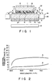
- Fig. 1 is a sectional view illustrating a first reference liquid-crystal display apparatus 12.
- apparatus 12 comprises first substrate 1 and second substrate 2, both made of, for example, glass.
- Transparent electrodes 3 are formed on first major surface 1a of first substrate 1.
- transparent electrodes 4 are formed on first major surface 2a of second substrate 2.
- Electrodes 3 and 4 are made of, for example, ITO (Indium Tin Oxide).
- Substrates 1 and 2 are parallel, and set apart for about 7.0 ⁇ , such that their first major surfaces 1a and 2a oppose to each other.
- First aligning layer 5 is formed on first major surface 1a of first substrate 1, covering transparent electrodes 3.
- Second aligning layer 6 is formed on first major surface 2a of second substrate 2, covering transparent electrodes 4.
- Sealing member 7 is made of, for example, an adhesive which hardens when applied with ultraviolet rays adheres both first and second substrate 1, 2, thus defining a closed space.
- This space is filled with nematic liquid crystal material 8.
- the nematic liquid crystal material 8 contains chiral agent formed of, for example, S8ll (trade mark: produced by Merk Co.).
- S8ll trade mark: produced by Merk Co.
- the molecular axis of liquid crystal material 8 twists by 180° to 360° from first substrate 1 to second substrate 2. For instance, this axis can twist counterclockwise by 200°.
- liquid crystal material 8 is pre-tilted by an angle ⁇ of more than 1°, i.e., about 10°, with respect to first and second major surfaces 1a and 2a of substrates 1 and 2.
- Liquid crystal material 8 has optical anisotropy ⁇ n of approximately 0.094.
- First neutral polarizer 9 is attached on second major surface 1b of first substrate 1.
- Optical retardation plate 10 made of, for example, a birefringent resin (i.e., polycarbonate, polyvinyl alcohol, etc.) is formed on second major surface 2b of second substrate 2.
- Second neutral polarizer 11 is formed on optical retardation plate 10.
- Polarizers 9 and 11 are positioned such that their polarizing axes are rotated clockwise by about 80° and about 45°, respectively, with respect to the aligning direction of first aligning layer 5. This specific positional relationship between polarizers 9 and 11 sets the apparatus substantially to the blue mode.
- R' The value of R', or ⁇ n' ⁇ d', ranges from 0.22+0.55m to 0.42+0.65m, or from 0.47+0.55m to 0.67+0.65m, where ⁇ n′ is the optical anisotropy of optical retardation plate 10 arranged between the polarizers 9 and 11 and d′ ( ⁇ m) is the thickness of optical retardation plate 10.
- d′ the thickness of optical retardation plate 10.
- liquid-crystal display apparatus 12 further comprises light-source 13 and two drive circuits 14.
- Light source 13 is located behind the optical retardation plate 10.
- Light source 13 is either an EL (Electroluminescence) lamp or a combination of an incandescent lamp or a fluorescent lamp and a light guiding plate, and applies light uniformly onto the entire surface of second polarizer 11.
- Two drive circuits 14 are located at the sides (i.e., the left and right sides, in Fig. 1).
- Either drive circuit comprises circuit board 16 and electronic components 15 mounted on board 16. Both circuits 14 are electrically connected to transparent electrodes 4 formed on second substrate 2, by means of connectors 17 such as flexible sheets.
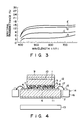
- Fig. 2 is a graph representing the spectral transmittance of the LCD cell.
- the curve A shows the spectral transmittance when no voltage is applied to the layer of liquid crystal material 8
- the curve B shows the spectral transmittance when a voltage is applied to the layer of liquid crystal material 8.
- the spectral transmittance of the background color of the transmitting light, generated by interference phenomenon is virtually made constant to give a black-white display.
- the spectral transmittance is complemented by optical retardation plate 10.
- the spectral transmittance becomes almost constant to give a black display.
- the color coordinates (x, y) of the background color is (0.321, 0.343), and that (x, y) of the display color is (0.330, 0.347).
- the liquid-crystal display apparatus 12 give the black display on the white background.
- Apparatus 12 can achieve color display, with a high color-reproducibility and in a high image contrast, by arranging a color filter before or after polarizers 9 or 11, or on first major surfaces 1a or 2a of substrates 1 or 2.
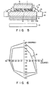
- Fig. 3 shows how the relationship between the spectral transmittance and wavelength of the light depends upon the voltage applied to the liquid-crystal layer.
- the curve B represents how the transmittance varies with the wavelength when a selective voltage is applied to the liquid-crystal layer.
- the curve E indicates how the transmittance changes with the wavelength when non-selective voltage is applied to the liquid-crystal layer.
- the curves C and D show how the transmittance varies with the wavelength when voltages between the selective voltage and the non-selective voltage are applied to the liquid-crystal layer.
- Liquid-crystal display apparatus 12 can accomplish better gray scale display than the conventional birefringent liquid-crystal display apparatuses.
- apparatus 12 when apparatus 12 is used in combination with color filters, thus performing gray scale display (full color display), no color change occurs, unlike in the prior art liquid-crystal display apparatuses.
- Apparatus 12 can therefore achieve a full color display, with a high color reproducibility.
- display quality means what is defined by the degree of whiteness of the background, the level of brightness of the background, and the contrast ratio of the liquid-crystal display apparatus of the structure identical to that shown in Fig. 1. This quality changes with the value R, which is determined by the optical anisotropy ⁇ n of nematic liquid crystal 8, the thickness d ( ⁇ m) of the layer of liquid crystal 8, and the pre-tilt angle ⁇ of liquid crystal 8.
- R which is determined by the optical anisotropy ⁇ n of nematic liquid crystal 8
- the thickness d ( ⁇ m) of the layer of liquid crystal 8 the pre-tilt angle ⁇ of liquid crystal 8.
- the arrows indicate the tendency of the respective items to change.
- the degree of background whiteness increases as R decreases.
- the contrast ratio and the level of background brightness decreases as the value of R decreases; in the worst case, light must be applied from behind the liquid-crystal display to compensate for the insufficiency of the background brightness.
- the greater the value of R the greater the degree to which the background is colored.
- the liquid-crystal display apparatus provides satisfactory display quality when R ranges from 0.4 to 0.8, and excellent display quality when R falls within the range of 0.6 to 0.75.
- R is less than 0.4, both the contrast ratio and the the level of the background brightness are too low, and the apparatus must be backlighted.
- R is greater than 0.8, the background is slightly colored, though the contrast ratio and the level of the background brightness are sufficiently high.
- R' ⁇ n ⁇ d'
- R' is 0.32
- a black-white display is obtained.
- the background is increasingly colored as R' approaches the lower limit of 0.22 or the upper limit of 0.42.
- m is 3 or more, the background is colored to an excessive degree, and liquid-crystal apparatus 12 can no longer be practical.
- the value of R' therefore, is most preferably about 0.32.
- the molecular of liquid crystal 8 can be twisted by 180° to 360°.
- the twist angle of the liquid-crystal molecules falls within a narrow range, from 210° to 270°.
- the twist angle is less than 210°, the level of the background brightness is lower than required.
- the twist angle is greater than 270°, the liquid crystal 8 exhibits hysteresis.
- the twist angle should best be about 270°, to provide adequate contrast ratio, sufficient level of background brightness, and required degree of background whiteness.
- a modification (not shown) of display apparatus 12 will be described. This modification is different from apparatus 12 (Fig. 1) in the polarizing axes of polarizers 9 and 11 and the value of R'. More specifically, polarizers 9 and 11 are positioned such that their polarizing axes are rotated clockwise by about 135° and about 45°, respectively, with respect to the orientating direction of first substrate 1. This specific positional relationship between polarizers 9 and 11 sets the apparatus to the yellow mode.
- the elongated axis of optical retardation plate 10 is rotated clockwise by about 110° with respect to the aligning direction of first substrate 1.
- the liquid-crystal molecules are twisted counterclockwise by 270° from first substrate 1 to second substrate 2, and are pre-tilted by angle ⁇ of 10°.
- Nematic liquid crystal material 8 used has optical anisotropy ⁇ n of 0.094.
- R 0.64, which value is identical to that of the liquid-crystal display apparatus shown in Fig. 1.
- the relationship between the spectral transmittance and the wavelength, which is observed in this modified liquid-crystal display apparatus, is the same as is shown in Fig. 2. Further, the spectral transmittance of the background color is virtually constant. The image can be displayed in black on the bright achromatic background.
- R' is 0.57
- a black-white display is given.
- the twist angle of the liquid-crystal molecules should better range from 210° to 270°, and most preferably be about 270°.
- Fig. 4 is a sectional view showing a second reference liquid-crystal display apparatus.
- the same numerals are used to designate the similar or the same components as those shown in Fig. 1.
- the apparatus shown in Fig. 4 is identical in structure to the apparatus of Fig. 1, except for the location of optical retardation plate 10. More specifically, optical retardation plate 10 is arranged between first substrate 1 and first polarizer 9. This apparatus can not only achieve the same advantages as the first embodiment (Fig. 1). But also can it reduce the nonuniformity of the background color, despite the non-uniform thickness of optical retardation plate 10, to a greater extent than the first embodiment wherein optical retardation plate 10 is located between second substrate 2 and second polarizer 11. The second embodiment therefore has great practical usefulness.
- the advantage resulting from the arranging optical retardation plate 10 between first substrate 1 and first polarizer 9, i.e., the reduction of color-nonuniformity, is prominent in the apparatus of a reflective type.
- the apparatus of a transmissive type has some degree of the advantage. This is because the apparatus of a transmissive type function also as the apparatus of a reflective type, since the ambient light is incident to the apparatus.
- the following example is related to the case that the apparatus has one or more plates in addition to the optical retardation member.
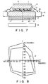
- Fig. 5 is a sectional view illustrating a third reference liquid-crystal display apparatus.
- This apparatus is characterized by the use of a combination of a optical retardation plate and a wave plate. More specifically, as is shown in Fig. 5, optical retardation plate 10a is formed on the lower surface of second substrate 2, and half-wave plate 10b is interposed between optical retardation plate 10a and second polarizer 11.
- the elongating axis of optical retardation plate 10a is located to rotate clockwise by about 110° with respect to the aligning direction of first substrate 1.
- the phase-advancing (or phase-lagging) axis of half-wave plate 10b is inclined at about 45° with respect to the light-absorption (or polarizing) axis of second polarizer 11.
- Fig. 6 is a diagram representing the viewing angle range of the apparatus shown in Fig. 5, and also that of a liquid-crystal display apparatus which is different only in that no half-wave plate 10b are used.
- A indicates the viewing angle range of the apparatus without half-wave plate 10b
- B represents that of the apparatus shown in Fig. 6.
- the X axis and the Y axis of this diagram are substantially parallel to the aligning directions in which the major surfaces la and 2a of the substrates 1 and 2 have been rubbed.
- the viewing angles, plotted on both axes, are of the values measured from the line perpendicular to the display surface of liquid-display apparatus. As is evident from Fig.
- the viewing angle range of the apparatus with half-wave plate 10b is broader than that of the apparatus without such a wave plate.
- the spectral transmittance curve has the same configuration as is shown in Fig. 2, when viewed from the front of the apparatus. In other words, the transmittance-wavelength relationship does not depend upon whether a half-wave plate is used or not.
- Table 2 shows the relationship between the angle ⁇ (°) and the degree of background whiteness, said angle ⁇ defined by the angle between the phase-advancing (or phase-lagging) axis of half-wave plate 10b and the light-absorbing (or polarizing) axis of second polarizer 11.
- Table 2 Angle ⁇ (°) Whiteness of Background 0 Colored ⁇ ⁇ 35 Slightly Colored 40 ⁇ 45 Not Colored 50 ⁇ 55 Slightly Colored ⁇ ⁇ 90 Colored
- the angle ⁇ when the angle ⁇ is 45°, the background appears white or rather transparent when viewed from the front, and image displayed appears black. Further, the viewing angle range is relatively broad. When the angle ⁇ ranges from about 40° to about 50°, a black-white display can be essentially given, though the background looks slightly colored. When the angle ⁇ falls outside this range (i.e., 40° to about 50°), the background is colored too much, in yellow, yellowish-green, blue, or purple, depending upon the values of R and R'.
- the axis of half-wave plate 10b (the phase-advancing axis or phase-lagging axis) is selected as the reference line for measuring the angle ⁇ .
- the angle ⁇ fall within the range of about 40° to 50°. The best value is about 45°.
- Fig. 7 is a sectional view showing a liquid-crystal display apparatus according to an embodiment of the present invention.
- This apparatus is identical to the third reference display (Fig. 5), except that quarter-wave plate 20 is used in place of half-wave plate 10b.
- the value R' of quarter-wave plate 20 is approximately 0.16 ⁇ m.
- the phase-advancing (or phase-lagging) axis of quarter-wave plate 20 is inclined at about 45° with respect to the light-absorbing (or polarizing) axis of second polarizer 11, as in the display illustrated in Fig. 5.
- the spectral transmittance curve has the same configuration as is shown in Fig. 2, when viewed from the front of the apparatus in either cases that a voltage is applied or not applied on the liquid-crystal layer. In other words, the transmittance-wavelength relationship does not depend upon whether or not quarter-wave plate is used or not.
- Fig. 8 is a diagram representing the viewing angle range of the apparatus shown in Fig. 7, which has includes quarter-wave plate 20, and also that of a liquid-crystal display apparatus which is identical to the apparatus shown in Fig. 7, except that no quarter-wave plate are provided.
- C represents the viewing-angle range of the apparatus without quarter-wave plate 20, and D indicates that of the apparatus (Fig. 7) with quarter-wave plate 20.
- the viewing angle range of the apparatus with quarter-wave plate 10b is broader than that of the apparatus without such a wave plate.
- the viewing angle range achieved by the use of quarter-wave plate 20 is broader than that attained by the use of half-wave plate 10b.
- the angle ⁇ range from about 40° to 50°, and the optimum value of this angle is about 45°.
- optical retardation plate 10 is not necessarily be arranged between first substrate 1 and first polarizer 9, or between second substrate 2 and second polarizer 11.
- Plate 10 can be located at any other position between polarizers 9 and 11. As long as optical retardation plate 10 is arranged between polarizers 9 and 11, the spectral transmittance is virtually invariable in the visible constant to give an excellent whiteness and blackness display.
- first substrate 1 or second substrate 2 can be used not only as a substrate, but also as an optical retardation plate. In this case, too, the same advantages are achieved as in the embodiments described above.
- half-wave plate 10b or quarter-wave plate 20 is positioned to contact with optical retardation plate 10.
- either wave plate can be located near either first substrate 1 or second substrate 2.
- the present invention can provide a liquid-crystal display apparatus which can perform ideal black-white display in such a way that the users can clearly recognize the display image, without the difference in their visibility.
- the apparatus according to the invention has a little color nonuniformity on its display surface, and can thus be manufactured with a high yield. Further, since the color changes very little with the viewing angle and the ambient temperature, the apparatus can accomplish excellent color display.
- the invention can apply to a liquid-crystal display apparatus of transmissive type, which can achieve a full-color and good gray scale, thus realizing good color reproducibility.
Landscapes
- Physics & Mathematics (AREA)
- Nonlinear Science (AREA)
- Chemical & Material Sciences (AREA)
- Crystallography & Structural Chemistry (AREA)
- General Physics & Mathematics (AREA)
- Optics & Photonics (AREA)
- Mathematical Physics (AREA)
- Liquid Crystal (AREA)
Claims (6)
- Dispositif d'affichage à cristaux liquides (12), comprenant:- des premier et deuxième substrats (1, 2) disposés en face l'un de l'autre et ayant des électrodes (3, 4) formées sur les surfaces en regard (1a, 2a) de ceux-ci, lesdites électrodes étant transparentes;- une couche de cristaux liquides nématiques (8) décrite par R = ▲n·d·cos20, ou ▲n est l'anisotropie optique de la matière constituée de cristaux liquides de ladite couche de cristaux liquides nématiques (8), d (µm) est l'épaisseur de ladite couche de cristaux liquides nématiques (8), et θ est l'angle de pré-inclinaison de ladite matière constituée de cristaux liquides nématiques interposée entre lesdits premier et deuxième substrats (1, 2) et ayant l'angle de pré-inclinaison θ plus grand que 1° par rapport aux surfaces (1a, 2a) desdits premier et deuxième substrats (1, 2) et ayant un angle d'hélice de 180° à 360° dudit premier substrat (1) audit deuxième substrat (2);- un premier polariseur (9) disposé sur la face dudit premier substrat (1) qui est opposée à l'électrode (3) formée sur celui-ci;- un deuxième polariseur (11) disposé sur la face dudit deuxième substrat (2) qui est opposée à l'électrode (3) formée sur celui-ci; et- un organe de retardement optique (10) décrit par R' = ▲n·d', ou ▲n' est l'anisotropie optique dudit organe de retardement optique (10) et d' (µm) est l'épaisseur dudit organe de retardement optique (10) situé entre lesdits premier et deuxième polariseurs (9, 11),caractérisé en ce que:- ledit dispositif d'affichage comprend en outre une lame quart d'onde (20) située entre lesdits premier et deuxième polariseurs (9, 11) et la valeur de R = ▲n·d'·cos20 est comprise dans la gamme de 0,4 à 0,8, et la valeur de R' = ▲n'·d' est comprise, dans le mode bleu, dans la gamame de 0,22 + 0,55 m à 0,42 + 0,65 m, ou de 0,47 + 0,55 m à 0,67 + 0,65 m (m = 0, 1 ou 2), ou, dans le mode jaune, de 0,47 + 0,55 m à 0,67 + 0,65 m (m = 0, 1 ou 2).
- Dispositif selon la revendication 1, caractérisé en ce que ledit organe de retardement optique (10) est une lame de retardement optique.
- Dispositif selon la revendication 1 ou 2, caractérisé en ce que ledit organe de retardement optique (10) est disposé soit entre l'électrode (3) dudit premier substrat (1) et ledit premier polarisieur (9) ou entre l'électrode (4) dudit deuxièmes substrat (2) et ledit deuxième polariseur (11).
- Dispositif selon l'une quelconque des revendications 1 à 3, caractérisé en ce que la valeur de R est comprise dans la gamme de 0,6 à 0,8.
- Dispositif selon l'une quelconque des revendications 1 à 4, caractérisé en ce que la valeur de R' est comprise dans la gamme de 0,22 à 0,42 ou de 0,47 à 0,67.
- Dispositif selon l'une quelconque des revendications 1 à 5, caractérisé en ce que l'angle d'hélice de ladite couche de cristaux liquides nématiques (8) est compris dans la gamme de 210° à 270°.
Applications Claiming Priority (8)
| Application Number | Priority Date | Filing Date | Title |
|---|---|---|---|
| JP112506/88 | 1988-05-11 | ||
| JP11250688 | 1988-05-11 | ||
| JP130378/88 | 1988-05-30 | ||
| JP13037888 | 1988-05-30 | ||
| JP131415/88 | 1988-05-31 | ||
| JP13141588 | 1988-05-31 | ||
| JP38231/88 | 1989-02-20 | ||
| JP1038231A JPH02124526A (ja) | 1988-05-11 | 1989-02-20 | 液晶表示器 |
Publications (3)
| Publication Number | Publication Date |
|---|---|
| EP0341702A2 EP0341702A2 (fr) | 1989-11-15 |
| EP0341702A3 EP0341702A3 (fr) | 1990-10-24 |
| EP0341702B1 true EP0341702B1 (fr) | 1996-10-16 |
Family
ID=27460554
Family Applications (1)
| Application Number | Title | Priority Date | Filing Date |
|---|---|---|---|
| EP89108439A Expired - Lifetime EP0341702B1 (fr) | 1988-05-11 | 1989-05-10 | Dispositif d'affichage à cristal liquide |
Country Status (3)
| Country | Link |
|---|---|
| US (1) | US5082353A (fr) |
| EP (1) | EP0341702B1 (fr) |
| DE (1) | DE68927332T2 (fr) |
Families Citing this family (17)
| Publication number | Priority date | Publication date | Assignee | Title |
|---|---|---|---|---|
| JP2856401B2 (ja) * | 1988-07-08 | 1999-02-10 | 株式会社東芝 | 液晶表示素子 |
| JPH0237319A (ja) * | 1988-07-27 | 1990-02-07 | Toshiba Corp | 液晶表示素子 |
| US5150237A (en) * | 1989-05-15 | 1992-09-22 | Ricoh Company, Ltd. | Liquid crystal display element |
| US5465103A (en) * | 1989-08-28 | 1995-11-07 | Mitsubishi Denki Kabushiki Kaisha | Display device with coordinate input function |
| US5175638A (en) * | 1989-09-12 | 1992-12-29 | Ricoh Company, Ltd. | ECB type liquid crystal display device having birefringent layer with equal refractive indexes in the thickness and plane directions |
| US5184237A (en) * | 1990-03-27 | 1993-02-02 | Ricoh Company, Ltd. | Super-twisted nematic type liquid crystal display device |
| US5250214A (en) * | 1990-04-09 | 1993-10-05 | Ricoh Company, Ltd. | Liquid crystal color display device provided with a color filter film and an optical phase plate comprising liquid crystal polymer |
| US5380459A (en) * | 1990-04-20 | 1995-01-10 | Ricoh Company, Ltd. | Liquid crystal display device with improved viewing angle dependence of color |
| JP3011993B2 (ja) * | 1990-10-26 | 2000-02-21 | 株式会社リコー | カラー液晶素子 |
| JPH0545667A (ja) * | 1991-08-20 | 1993-02-26 | Hitachi Ltd | ドツトマトリクス型表示装置 |
| JPH11509651A (ja) * | 1996-05-17 | 1999-08-24 | フィリップス エレクトロニクス ネムローゼ フェンノートシャップ | 液晶表示装置及び偏光子を有する光学部品 |
| JPH1062811A (ja) * | 1996-08-20 | 1998-03-06 | Toshiba Corp | 液晶表示素子及び大型液晶表示素子並びに液晶表示素子の駆動方法 |
| JP3286579B2 (ja) * | 1997-10-13 | 2002-05-27 | 三洋電機株式会社 | 透過型液晶表示装置 |
| TW200504408A (en) * | 2003-07-25 | 2005-02-01 | Au Optronics Corp | A method for repairing the light spot of the liquid crystal display |
| US20060001826A1 (en) * | 2004-07-05 | 2006-01-05 | Da-Shuang Kuan | [reflective liquid crystal micro display panel] |
| US20060023142A1 (en) * | 2004-07-28 | 2006-02-02 | Arima Display Corp. | Liquid crystal display panel |
| JP5143484B2 (ja) * | 2007-07-09 | 2013-02-13 | 株式会社ジャパンディスプレイウェスト | 表示装置および電子機器 |
Citations (2)
| Publication number | Priority date | Publication date | Assignee | Title |
|---|---|---|---|---|
| EP0131216A2 (fr) * | 1983-07-12 | 1985-01-16 | BBC Brown Boveri AG | Affichage à cristaux liquides |
| EP0311339A2 (fr) * | 1987-10-07 | 1989-04-12 | Matsushita Electric Industrial Co., Ltd. | Afficheur à cristal liquide |
Family Cites Families (12)
| Publication number | Priority date | Publication date | Assignee | Title |
|---|---|---|---|---|
| JPS4946954A (fr) * | 1972-09-11 | 1974-05-07 | ||
| DE2329618A1 (de) * | 1973-06-09 | 1975-01-02 | Fraunhofer Ges Forschung | Anordnung zur vielfarbigen anzeige, bestehend aus lichtquelle und linearpolarisationsfilter |
| GB1469638A (en) * | 1973-07-18 | 1977-04-06 | Secr Defence | Liquid crystal display device |
| US4443065A (en) * | 1980-12-09 | 1984-04-17 | Sharp Kabushiki Kaisha | Interference color compensation double layered twisted nematic display |
| JPS6073525A (ja) * | 1983-09-30 | 1985-04-25 | Hitachi Ltd | 液晶表示素子 |
| GB2171549B (en) * | 1985-02-15 | 1988-05-18 | Citizen Watch Co Ltd | Liquid crystal display device |
| JPS61261722A (ja) * | 1985-05-16 | 1986-11-19 | Matsushita Electric Ind Co Ltd | 液晶表示装置 |
| DE3752219T2 (de) * | 1986-05-19 | 1999-02-18 | Seiko Epson Corp., Tokio/Tokyo | Flüssigkristall-Anzeigevorrichtung |
| JPS63234225A (ja) * | 1987-03-23 | 1988-09-29 | Sharp Corp | 液晶表示装置 |
| JPS63274925A (ja) * | 1987-05-07 | 1988-11-11 | Asahi Glass Co Ltd | 液晶表示素子 |
| JPH01120527A (ja) * | 1987-11-04 | 1989-05-12 | Sharp Corp | 液晶表示装置 |
| US4984874A (en) * | 1988-07-08 | 1991-01-15 | Kabushiki Kaisha Toshiba | Liquid crystal display device having retardation films |
-
1989
- 1989-05-08 US US07/348,422 patent/US5082353A/en not_active Expired - Lifetime
- 1989-05-10 EP EP89108439A patent/EP0341702B1/fr not_active Expired - Lifetime
- 1989-05-10 DE DE68927332T patent/DE68927332T2/de not_active Expired - Fee Related
Patent Citations (2)
| Publication number | Priority date | Publication date | Assignee | Title |
|---|---|---|---|---|
| EP0131216A2 (fr) * | 1983-07-12 | 1985-01-16 | BBC Brown Boveri AG | Affichage à cristaux liquides |
| EP0311339A2 (fr) * | 1987-10-07 | 1989-04-12 | Matsushita Electric Industrial Co., Ltd. | Afficheur à cristal liquide |
Also Published As
| Publication number | Publication date |
|---|---|
| US5082353A (en) | 1992-01-21 |
| EP0341702A2 (fr) | 1989-11-15 |
| DE68927332T2 (de) | 1997-03-20 |
| DE68927332D1 (de) | 1996-11-21 |
| EP0341702A3 (fr) | 1990-10-24 |
Similar Documents
| Publication | Publication Date | Title |
|---|---|---|
| EP0341702B1 (fr) | Dispositif d'affichage à cristal liquide | |
| JP3339334B2 (ja) | 反射型液晶表示素子 | |
| EP0576303A1 (fr) | Dispositif d'affichage à cristal liquide du type réflectif | |
| EP0498614B1 (fr) | Dispositif d'affichage à cristal liquide | |
| US6456347B1 (en) | Liquid crystal display | |
| EP0392811A2 (fr) | Dispositif à cristal liquide du type par transmission | |
| EP0350063A2 (fr) | Dispositif d'affichage à cristal liquide | |
| KR100629984B1 (ko) | 색불균일에 효과적인 액정표시장치 | |
| EP0350062B1 (fr) | Dispositif d'affichage à cristaux liquides | |
| US6480251B1 (en) | Reflection liquid crystal display element | |
| EP0368554B1 (fr) | Dispositif d'affichage comprenant un cristal liquide nématique torsadé | |
| EP1403690B1 (fr) | Dispositif d'affichage à cristaux liquides | |
| KR19990036581A (ko) | 액정 표시 장치 | |
| KR20010042793A (ko) | 반사형 액정표시소자 | |
| JP2887776B2 (ja) | 液晶表示装置 | |
| US6686983B2 (en) | Reflection type liquid crystal display device with high-brightness bright display and high contrast | |
| JPH04289818A (ja) | 液晶表示装置 | |
| JPH06186553A (ja) | 液晶表示装置 | |
| JPH07333594A (ja) | 液晶表示装置 | |
| JPH1078575A (ja) | 液晶表示装置 | |
| JP3452743B2 (ja) | 液晶表示装置 | |
| US6163667A (en) | Semi-transmissive liquid crystal display device free from reversal of display on screen | |
| JP3560164B2 (ja) | 液晶表示装置 | |
| JPH06347762A (ja) | 液晶表示装置 | |
| JP3804252B2 (ja) | 液晶装置及び電子機器 |
Legal Events
| Date | Code | Title | Description |
|---|---|---|---|
| PUAI | Public reference made under article 153(3) epc to a published international application that has entered the european phase |
Free format text: ORIGINAL CODE: 0009012 |
|
| 17P | Request for examination filed |
Effective date: 19890607 |
|
| AK | Designated contracting states |
Kind code of ref document: A2 Designated state(s): DE FR GB |
|
| PUAL | Search report despatched |
Free format text: ORIGINAL CODE: 0009013 |
|
| AK | Designated contracting states |
Kind code of ref document: A3 Designated state(s): DE FR GB |
|
| 17Q | First examination report despatched |
Effective date: 19920915 |
|
| GRAG | Despatch of communication of intention to grant |
Free format text: ORIGINAL CODE: EPIDOS AGRA |
|
| GRAH | Despatch of communication of intention to grant a patent |
Free format text: ORIGINAL CODE: EPIDOS IGRA |
|
| GRAH | Despatch of communication of intention to grant a patent |
Free format text: ORIGINAL CODE: EPIDOS IGRA |
|
| GRAA | (expected) grant |
Free format text: ORIGINAL CODE: 0009210 |
|
| AK | Designated contracting states |
Kind code of ref document: B1 Designated state(s): DE FR GB |
|
| REF | Corresponds to: |
Ref document number: 68927332 Country of ref document: DE Date of ref document: 19961121 |
|
| ET | Fr: translation filed | ||
| PLBE | No opposition filed within time limit |
Free format text: ORIGINAL CODE: 0009261 |
|
| STAA | Information on the status of an ep patent application or granted ep patent |
Free format text: STATUS: NO OPPOSITION FILED WITHIN TIME LIMIT |
|
| 26N | No opposition filed | ||
| REG | Reference to a national code |
Ref country code: GB Ref legal event code: 746 Effective date: 19981012 |
|
| REG | Reference to a national code |
Ref country code: FR Ref legal event code: D6 |
|
| REG | Reference to a national code |
Ref country code: GB Ref legal event code: IF02 |
|
| PGFP | Annual fee paid to national office [announced via postgrant information from national office to epo] |
Ref country code: DE Payment date: 20060508 Year of fee payment: 18 |
|
| PGFP | Annual fee paid to national office [announced via postgrant information from national office to epo] |
Ref country code: GB Payment date: 20060510 Year of fee payment: 18 |
|
| PGFP | Annual fee paid to national office [announced via postgrant information from national office to epo] |
Ref country code: FR Payment date: 20060515 Year of fee payment: 18 |
|
| GBPC | Gb: european patent ceased through non-payment of renewal fee |
Effective date: 20070510 |
|
| REG | Reference to a national code |
Ref country code: FR Ref legal event code: ST Effective date: 20080131 |
|
| PG25 | Lapsed in a contracting state [announced via postgrant information from national office to epo] |
Ref country code: DE Free format text: LAPSE BECAUSE OF NON-PAYMENT OF DUE FEES Effective date: 20071201 |
|
| PG25 | Lapsed in a contracting state [announced via postgrant information from national office to epo] |
Ref country code: GB Free format text: LAPSE BECAUSE OF NON-PAYMENT OF DUE FEES Effective date: 20070510 |
|
| PG25 | Lapsed in a contracting state [announced via postgrant information from national office to epo] |
Ref country code: FR Free format text: LAPSE BECAUSE OF NON-PAYMENT OF DUE FEES Effective date: 20070531 |