EP0341545B1 - Prise de connexion électrique verrouillable - Google Patents
Prise de connexion électrique verrouillable Download PDFInfo
- Publication number
- EP0341545B1 EP0341545B1 EP89107898A EP89107898A EP0341545B1 EP 0341545 B1 EP0341545 B1 EP 0341545B1 EP 89107898 A EP89107898 A EP 89107898A EP 89107898 A EP89107898 A EP 89107898A EP 0341545 B1 EP0341545 B1 EP 0341545B1
- Authority
- EP
- European Patent Office
- Prior art keywords
- clip
- housing
- plug
- lever
- plug connection
- Prior art date
- Legal status (The legal status is an assumption and is not a legal conclusion. Google has not performed a legal analysis and makes no representation as to the accuracy of the status listed.)
- Expired - Lifetime
Links
- 238000003780 insertion Methods 0.000 claims description 6
- 230000037431 insertion Effects 0.000 claims description 6
- 230000000694 effects Effects 0.000 claims description 2
- 230000007480 spreading Effects 0.000 description 6
- 230000008878 coupling Effects 0.000 description 4
- 238000010168 coupling process Methods 0.000 description 4
- 238000005859 coupling reaction Methods 0.000 description 4
- 239000000463 material Substances 0.000 description 3
- 238000002347 injection Methods 0.000 description 2
- 239000007924 injection Substances 0.000 description 2
- 238000000034 method Methods 0.000 description 2
- 230000008569 process Effects 0.000 description 2
- 230000002787 reinforcement Effects 0.000 description 2
- 230000000284 resting effect Effects 0.000 description 2
- 229910000639 Spring steel Inorganic materials 0.000 description 1
- 230000000903 blocking effect Effects 0.000 description 1
- 238000002485 combustion reaction Methods 0.000 description 1
- 230000000295 complement effect Effects 0.000 description 1
- 238000006073 displacement reaction Methods 0.000 description 1
- 230000005489 elastic deformation Effects 0.000 description 1
- 239000013013 elastic material Substances 0.000 description 1
- 230000002349 favourable effect Effects 0.000 description 1
- 238000001746 injection moulding Methods 0.000 description 1
- 238000010409 ironing Methods 0.000 description 1
- 230000009467 reduction Effects 0.000 description 1
- 230000003014 reinforcing effect Effects 0.000 description 1
- 230000000630 rising effect Effects 0.000 description 1
- 238000007789 sealing Methods 0.000 description 1
- 230000007704 transition Effects 0.000 description 1
Images
Classifications
-
- H—ELECTRICITY
- H01—ELECTRIC ELEMENTS
- H01R—ELECTRICALLY-CONDUCTIVE CONNECTIONS; STRUCTURAL ASSOCIATIONS OF A PLURALITY OF MUTUALLY-INSULATED ELECTRICAL CONNECTING ELEMENTS; COUPLING DEVICES; CURRENT COLLECTORS
- H01R13/00—Details of coupling devices of the kinds covered by groups H01R12/70 or H01R24/00 - H01R33/00
- H01R13/62—Means for facilitating engagement or disengagement of coupling parts or for holding them in engagement
Definitions
- the invention is directed to a lockable electrical plug connection of the type mentioned in the preamble of claim 1.
- the coupling of the plug part in the socket part is secured by the latching sections of the bow spring which engage counter-latching lugs on the inserted plug part.
- the spring clip To release the plug-in connection, the spring clip must first be moved, as a result of which the clip legs run up on slants located on the housing and are spread apart. As a result, they come out of the insertion path of the counter-locking lugs, whereby the connector part is released.
- the spring clip In the known plug-in connection (DE-OS 31 50 424) the spring clip is released in parallel in its plane to release the lock. Determined by external grooves on the housing, the bracket level lies transversely to the direction of plug movement of the plug and socket part, which is why the locking release movement of the spring clip is carried out transversely to the housing.
- the bracket level In some applications, for example in the electrical connection for injection nozzles in internal combustion engines, there is a lack of space in the area of the plug connection, which is why the hand is hampered in the known transverse displacement of the spring clip for locking the plug connection.
- the invention has for its object to develop a simple, inexpensive connector of the type mentioned in the preamble of claim 1, which is more ergonomic to handle during the unlocking process, even under unfavorable space conditions, and yet is characterized by a high locking security.
- This is achieved according to the invention by the measures specified in the characterizing part of claim 1, which have the following special meaning:
- the entire spring clip acts as a lever, which is why its entire length can be used. According to the lever law, because of the large lever length, a relatively small actuating force that is easy to apply can overcome a large locking force that is determined by a high deformation force of the spring clip for the safety of the locking.
- the direction of the pivoting movement is at the same time the direction of the plug-in movement when coupling or uncoupling the plug and socket parts. You swivel in the direction in which the socket part is to be removed from the plug part. Because the pivoting movement takes place in the form of a circular arc, the wedge which engages under the stirrup legs is acted upon in increasing increasing direction of movement during the execution of the movement, which has a favorable effect on a smooth spreading. At the beginning of the handling a somewhat increased actuating force is required, especially if, according to claim 2, the wedge rises in the direction of the plug movement. The rest position of the spring clip is thus particularly secured.
- stirrup leg Relative to the individual stirrup legs of the plug connection according to the invention, two movements result during the unlocking process; the stirrup leg is pivoted in the direction of insertion when actuated and at the same time spread transversely to it due to the casserole on the wedge in order to bring its locking sections out of engagement with the counter-locking lugs of the coupled connector part.
- the pivot bearing point for moving the lever arm according to the invention is the wedge itself which engages under the bracket arm, as proposed in claim 3. Additional measures for this are unnecessary.
- the housing can be designed very simply if, as can be seen from claim 4, the wedge is designed as a bevel edge which expediently accompanies the entire arm leg.
- This inclined edge can also fulfill the function resulting from claim 5, to form an outer groove in the housing for receiving the bracket leg. The inclined edge thus serves in the rest position for positioning the bracket leg on the housing of the socket part.
- the spring clip could still be angled or bent in itself, but to save material and for reasons of space it is cheaper, as claim 8 suggests, to design the spring clip essentially in one plane.
- the handle of the spring clip should then also lie in this plane of the clip, especially if it is designed as a molded loop.
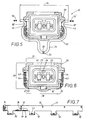
- the electrical connector according to the invention consists of two parts, namely a plug part of a known type (not shown in more detail) and a complementary socket part 10 which, as shown in FIG. 7, can be molded in four copies on a cable rail 11, which in turn, via closure halves 12, which interact with counter-closure halves of a cover part, can be completed to form a tubular cable duct.
- the channel interior 13 serves to guide the lines, which can be led out at the end channel openings, where retaining rails 14 are provided for receiving cable bushings, not shown in detail.
- the bottom area of the cable rail 11 is partially provided with weakened, penetrable bottom areas 15, through which electrical lines can be inserted or removed as required.
- the electrical lines are routed to the individual socket parts 10 and there through pipe sections 16 into the interior of sleeve-shaped housings 20. Between the housing foot 21 and the pipe sections 16 there are stiffening triangular ribs 17, as well, as can be seen from the outbreak of FIG. 7, in the channel interior 13 reinforcing ribs 18 are located on the inner wall.
- the housing 20 Inside the housing 20 is a housing core 22, in which chambers 23 are provided, in which, as It can be seen from FIG. 6 that the contact elements 24 on the socket side are mounted.
- the chambers are open to the pipe sections 16 for the passage of the electrical lines up to their connection points on the contact elements 24.
- the housing base 25 is profiled with a groove running around the core piece 22 and serves to mount a sealing ring (not shown in more detail).
- the housing 20 has a rectangular cross section which determines the housing side walls 26 and, as shown in FIG. 6, a housing front wall 28 and rear wall 29.
- the plug part (not shown in detail) is inserted through the housing opening 40 with its contact member in the direction shown by the movement arrow 19 of FIGS. 2 and 3.
- the arrow 19 thus determines the direction of plug movement and is the normal to the housing opening.
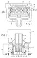
- the housing side walls 26 are, in a mirror image of each other, as is apparent from FIGS. 2, 3 and 6, provided with external grooves 27 which serve to receive a U-shaped resilient bracket 30.
- the outer grooves 27 run in a cross-sectional plane of the housing 20 and are thus transverse to the direction of plug-in movement 19.
- the rear wall 29 of the housing is provided with a cutout 41, which can also be seen in FIG. 7, while the front wall 28 of the housing has an inner guide groove 42 in the direction of travel the plug movement 19 carries for the plug part.
- the housing side walls 26 are, as shown in FIGS. 2 and 6, also provided with axial guide grooves 43, each of which creates an opening 44 for locking sections 32 of the bracket 30 in the height region of the outer grooves 27, which, as shown in FIG.
- the bracket 30 is made of elastic material, such as spring steel.
- the spring wire is bent into a flat structure, which defines the bow plane, which is also the plane of the drawing in FIG. 4.
- the U-shaped spring clip 30 has two clip legs 31 which are connected to one another by a clip web 33, which is formed into a loop 34 in the middle of the clip.
- At the temple ends there are convex bends 35 directed towards one another which, with their bend crowns, form the latching sections 32 already mentioned.
- the loop 34 and in particular its loop apex 36 are used for handling the spring clip 30, which also applies to the assembly of the socket part 10 according to the invention.
- the cable rail 11 with its various housings 20 is made of plastic by injection molding and the spring clip 30, independently of it, is prefabricated from wire.
- the spring clip 30 is pushed onto the housing 20 at the level of the outer grooves 27 on both sides.
- the two legs 31 strive to spring against one another by prestressing the wire material.
- their arcuate end pieces 37 run like runners on guide surfaces 45 at the transition point between the housing front wall 28 and side walls 26 shown in FIG. 6 and lead to a temporary bracket expansion until finally the cranked portions 35 with their latching sections 32 on the Breakthroughs 44 reach where they snap resiliently into the axial guide grooves 43.
- the bracket 30 is then captively held on the housing 20 and assumes its defined rest position.
- the rest position is characterized in that the bracket legs 31 lie between the two groove walls 47, 48 of the associated outer groove 27.
- the outer groove wall 48 as can be seen in FIG. 2, is essentially flat and is produced by an outer flange 46 which, however, as shown in FIGS. 1 and 2, only projects beyond the side walls 26 of the housing 20.
- the inner groove wall 47 belongs to a corresponding only laterally protruding inner flange 49 of the housing 20, the special feature of which is that it is a wedge-shaped, inclined edge 47 rising against the housing foot 21.
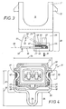
- the normal rest position of the bracket 30 is drawn drawn in Fig. 3.
- the bracket 30 is parallel to the outer groove 27.
- the forces acting in the merging direction between the two bracket legs 31 press against the groove base.
- the latching sections 32 engage in the axial guide grooves 43 shown in FIG. 6 and therefore lock latching lugs sliding along the connector part there when the connector is in the full coupling position in the socket part 10.
- the latching lugs are engaged behind by the latching sections 32 of the bracket and prevent the plug part from being pulled out of the socket part 10.
- the bracket plane 38 indicated by dash-dotted lines in FIG. 3 is located in a cross-sectional plane of the housing 20 and is therefore perpendicular to the one described Direction of insertion 19.
- the spring clip 30 is pivoted according to the invention in the sense of the movement arrow 51 shown in FIG. 3 in the direction of the housing foot 21.
- a handle 36 of the bracket 3 is exerted by an arrow 50 in FIG. 3, which points approximately in the direction of the plug movement 19 already mentioned several times.
- the actuation 50 of the bracket 30 thus takes place essentially in the same direction as the cable rail 11 equipped with the socket parts 10 is to be removed from the plug parts (not shown in more detail) which, in a corresponding arrangement pattern, are stuck, for example on the injection nozzles of a motor vehicle engine.
- the removal of the socket part on the one hand and the actuation of the bracket 30 on the other hand are therefore directionally the same.
- the spring clip 30 with its entire clip length 39 shown in FIG. 4 acts as a pivotable lever.
- the two bracket legs 31 run onto the inner inclined edge 47 that accompanies them toward the housing foot 21 and are thereby increasingly elastically spread out against one another in the course of the further pivoting.
- the legs 31 In the first phase of the pivoting 51, the legs 31 have to overcome the full wedge rise of the inclined edge 47, but the arc of this pivoting 51 then increasingly runs in the direction of a contour of the inclined edge 47, which is why the elastic deformation work of the two stirrup legs 31 when spreading in the first phase is greatest.
- the leg cross-section of the ironing wire which is cut in different areas in FIG. 2, moves onto the wedge-shaped oblique edges 47 and, spreading the arm legs, moves from the blocking positions 52, 53 drawn in solid lines to the release positions 52 ′, which are shown in dash-dot lines in FIG. 2, 53 ′.
- the section of the inclined edge 47 designated 55 in FIG. 3 functions as a pivot bearing point of the lever determined by its clip length 39. Due to the arcuate curvature of the leg end pieces 37, these can move in the spread 54 'shown in FIG. 5' in front of the outer flanges 46, whereby a large pivot angle at 51 is achieved. This promotes the reliability and convenience of handling.
- the U-shaped loop 34 not only increases the spring elasticity of the two brackets 31 during their spreading movement illustrated by the two arrows 56 in FIG. 5, but also increases the effective lever length 39 according to FIG. 4 because the loop 34 runs parallel to the bracket legs 31 . If the force 50 on the loop apex 36 is no longer exerted, pull the two bracket legs 31 together due to the spring elasticity. The spread 56 of FIG. 5 is reversed again and the bracket returns to its rest position of FIG. 4. The wedge-shaped oblique edges 47 in the outer groove 27 then guide the legs 31 back and engage under them in the rest position. As a result, the bracket 30 is supported over substantial length ranges.
- the lower groove wall 47 thus has multiple functions.
- bracket 30 does not have to lie in its entire length in a common bracket plane 38 according to FIG. 3, rather, in the area of the bracket legs or in the area of its handle, bends or curves are possible.
- the decisive factor is that by pivoting the bracket at one point, both locking sections are transferred into their release position 32 'according to FIG. 5. It can be operated with just one finger. The handling described can be carried out reliably even under unfavorable space conditions.
Landscapes
- Details Of Connecting Devices For Male And Female Coupling (AREA)
- Connector Housings Or Holding Contact Members (AREA)
Claims (9)
- Connecteur électrique verrouillable, constitué par une partie de prise comportant un élément de contact avec des talons de butée latéraux d'une part,
et d'une partie de douille (10) renfermant un élément de contre-contact (24) d'autre part avec un logement (20) en forme de gaine, comportant des chanfreins latéraux ainsi qu'un étrier à ressort (étrier à ressort 30), en forme de U fixé de façon mobile sur le logement (20),
dont les deux branches d'étriers élastiques (31) opposées entre elles forment des sections de butée (32) présentant des courbures (35) en position d'extrémité
qui pénètrent par les passages latéraux (44) du logement (20) dans la voie d'introduction (43) des talons de butée de la partie de prise d'une manière efficace pour le verrouillage
et dont l'aile d'étrier (33) reliant les branches d'étrier (31) forment une poignée (36) se trouvant à l'extérieur du logement (20) pour le déplacement de l'étrier à ressort ou étrier élastique (30) sur les chanfreins ou parties obliques dans le sens d'un écartement (56) des branches de l'étrier (31) au niveau de leur section de butée (32, 32')
caractérisé en ce que l'étrier élastique (30) forme avec toute sa longueur d'étrier (39) allant des extrémités courbées (37) des branches d'étrier (31) jusqu'à la poignée (36) un levier,
levier qui peut être mis en pivotement ou basculement (51) par une force d'actionnement (50) dirigée vers le socle du logement (21) dans la direction de mouvement de connexion (19) de la partie de la fiche et de la douille (10),
et les branches d'étrier (31) sont emprisonnées sur leur coté longitudinal tourné vers le socle de logement (31) respectivement par une clavette (47) logée dans le logement
qui s'élève dans le sens de pivotement (51) du levier (30) et sert à l'écartement (56) de la branche d'étrier (31). - Connecteur selon la revendication 1, caractérisé en ce que l'élévation de la clavette s'étend parallèlement à la direction de mouvement de connexion (19) de la partie fiche et douille (20).
- Connecteur selon la revendication 1 ou 2, caractérisé en ce que la clavette (47) forme simultanément la partie de palier de pivotement (55) du levier (30).
- Connecteur selon une ou plusieurs des revendications 1 à 3, caractérisé en ce que la clavette est formée par un bord oblique (47) s'étendant le long de la branche d'étrier (31).
- Connecteur selon la revendication 4, caractérisé en ce que le bord oblique (47) est la paroi de gorge interne d'une gorge externe (21) sur le logement (20) pour recevoir la branche d'étrier (31).
- Connecteur selon une ou plusieurs des revendications 1 à 5, caractérisé en ce que l'aile d'étrier (33) de l'étrier élastique (30) est de préférence munie dans la partie médiane de son aile d'une boucle (34) servant de poignée (36) du levier (30).
- Connecteur selon la revendication 6, caractérisé en ce que la boucle (34) augmente la longueur du levier et le sommet de la boucle (36) est la poignée du levier (30).
- Connecteur selon une ou plusieurs des revendications 1 à 7, caractérisé en ce que
les deux branches d'étrier (31) se situent avec leur courbe générant les sections de butée (32) dans un plan commun (plan d'étrier 38)
qui est agencé dans la position de repos du levier (30) perpendiculairement à la direction de déplacement de connexion (19) de la partie fiche et douille (10). - Connecteur selon la revendication 8, caractérisé en ce que
dans le plan d'étrier (38) se situe également la poignée (36) du levier (30)
et la direction de pivotement (51) du levier (30) s'étend perpendiculairement au plan de l'étrier (38).
Applications Claiming Priority (2)
| Application Number | Priority Date | Filing Date | Title |
|---|---|---|---|
| DE3815653A DE3815653A1 (de) | 1988-05-07 | 1988-05-07 | Verriegelbare elektrische steckverbindung |
| DE3815653 | 1988-05-07 |
Publications (3)
| Publication Number | Publication Date |
|---|---|
| EP0341545A2 EP0341545A2 (fr) | 1989-11-15 |
| EP0341545A3 EP0341545A3 (fr) | 1991-09-11 |
| EP0341545B1 true EP0341545B1 (fr) | 1994-04-06 |
Family
ID=6353895
Family Applications (1)
| Application Number | Title | Priority Date | Filing Date |
|---|---|---|---|
| EP89107898A Expired - Lifetime EP0341545B1 (fr) | 1988-05-07 | 1989-05-02 | Prise de connexion électrique verrouillable |
Country Status (3)
| Country | Link |
|---|---|
| EP (1) | EP0341545B1 (fr) |
| DE (2) | DE3815653A1 (fr) |
| ES (1) | ES2054921T3 (fr) |
Families Citing this family (1)
| Publication number | Priority date | Publication date | Assignee | Title |
|---|---|---|---|---|
| JP5005498B2 (ja) * | 2007-10-24 | 2012-08-22 | 日本圧着端子製造株式会社 | 掛け止め金具、掛け止め金具付きコネクタハウジング及び掛け止め金具付きコネクタ |
Family Cites Families (4)
| Publication number | Priority date | Publication date | Assignee | Title |
|---|---|---|---|---|
| DE2915574A1 (de) * | 1979-04-18 | 1980-10-23 | Harting Elektronik Gmbh | Gehaeusehaelften-verschluss fuer mehrpolige elektrische steckvorrichtungen |
| DE3150424C2 (de) * | 1981-06-16 | 1987-04-23 | Robert Bosch Gmbh, 7000 Stuttgart | Elektrische Steckvorrichtung |
| GB8504224D0 (en) * | 1985-02-19 | 1985-03-20 | Stewart A | Electrical connection |
| DE3531925A1 (de) * | 1985-09-07 | 1987-03-19 | Reinshagen Kabelwerk Gmbh | Verriegelbarer elektrischer steckverbinder |
-
1988
- 1988-05-07 DE DE3815653A patent/DE3815653A1/de active Granted
-
1989
- 1989-05-02 DE DE89107898T patent/DE58907378D1/de not_active Expired - Lifetime
- 1989-05-02 EP EP89107898A patent/EP0341545B1/fr not_active Expired - Lifetime
- 1989-05-02 ES ES89107898T patent/ES2054921T3/es not_active Expired - Lifetime
Also Published As
| Publication number | Publication date |
|---|---|
| ES2054921T3 (es) | 1994-08-16 |
| DE3815653A1 (de) | 1989-11-16 |
| DE3815653C2 (fr) | 1990-09-06 |
| EP0341545A3 (fr) | 1991-09-11 |
| DE58907378D1 (de) | 1994-05-11 |
| EP0341545A2 (fr) | 1989-11-15 |
Similar Documents
| Publication | Publication Date | Title |
|---|---|---|
| EP1867817B1 (fr) | Crémone | |
| EP0755341B1 (fr) | Bras d'essuie- glace, en particulier pour vehicules automobiles | |
| DE19714459C2 (de) | Steckverbinder mit einer Gehäuseverriegelung | |
| EP0601446A1 (fr) | Dispositif de verrouillage pour un dispositif de drainage | |
| DE4112132A1 (de) | Hebelwerk, insbesondere fusshebelwerk fuer kraftfahrzeuge | |
| DE19852395C2 (de) | Steckkupplung | |
| DE2116463B2 (de) | Kugelgelenk, insbesondere für Wischeranlagen in Kraftfahrzeugen | |
| EP0341545B1 (fr) | Prise de connexion électrique verrouillable | |
| EP2725957B1 (fr) | Manchon de raccordement permettant de raccorder des tubes à d'autres éléments | |
| DE2237946A1 (de) | Einsteck-clip fuer schreibgeraete | |
| DE19840642C2 (de) | Befestigungselement für einen Betätigungszug | |
| DE3246887C2 (de) | Stielbefestigungskupplung, insbesondere für Haus- und Gartengeräte | |
| DE2743796A1 (de) | Fernbetaetigung, insbesondere fuer die starterklappe von kraftfahrzeugen | |
| DE69516575T2 (de) | Befestigungselement für Kabel, Rohre oder dergleichen | |
| EP1127760B1 (fr) | Dispositif de contrôle d'un frein de stationnement | |
| DE202004019060U1 (de) | Kraftfahrzeugschloß | |
| DE20016618U1 (de) | Anhängerkupplung für Kraftfahrzeuge | |
| DE8809663U1 (de) | Verriegelbare elektrische Steckverbindung | |
| DE102011053088A1 (de) | Wischblatt für eine Wischeinrichtung eines Kraftfahrzeugs | |
| EP3655293B1 (fr) | Élément de fermeture | |
| DE9411104U1 (de) | Entriegelungswerkzeug für Karosserieklammern | |
| DE19618307B4 (de) | Verbindungsstück für einen Scheibenwischer | |
| DE102020104949A1 (de) | Hebel zum manuellen Entriegeln einer Sitzschienenanordnung | |
| DE102005048055B3 (de) | Halter für eine Stange | |
| DE3839911C2 (de) | Elektrischer Schalter |
Legal Events
| Date | Code | Title | Description |
|---|---|---|---|
| PUAI | Public reference made under article 153(3) epc to a published international application that has entered the european phase |
Free format text: ORIGINAL CODE: 0009012 |
|
| AK | Designated contracting states |
Kind code of ref document: A2 Designated state(s): BE DE ES FR GB IT SE |
|
| PUAL | Search report despatched |
Free format text: ORIGINAL CODE: 0009013 |
|
| AK | Designated contracting states |
Kind code of ref document: A3 Designated state(s): BE DE ES FR GB IT SE |
|
| 17P | Request for examination filed |
Effective date: 19910823 |
|
| RHK1 | Main classification (correction) |
Ipc: H01R 13/639 |
|
| 17Q | First examination report despatched |
Effective date: 19930913 |
|
| GRAA | (expected) grant |
Free format text: ORIGINAL CODE: 0009210 |
|
| AK | Designated contracting states |
Kind code of ref document: B1 Designated state(s): BE DE ES FR GB IT SE |
|
| ITF | It: translation for a ep patent filed | ||
| PG25 | Lapsed in a contracting state [announced via postgrant information from national office to epo] |
Ref country code: BE Effective date: 19940406 Ref country code: SE Free format text: THE PATENT HAS BEEN ANNULLED BY A DECISION OF A NATIONAL AUTHORITY Effective date: 19940406 |
|
| REF | Corresponds to: |
Ref document number: 58907378 Country of ref document: DE Date of ref document: 19940511 |
|
| GBT | Gb: translation of ep patent filed (gb section 77(6)(a)/1977) |
Effective date: 19940419 |
|
| ET | Fr: translation filed | ||
| REG | Reference to a national code |
Ref country code: ES Ref legal event code: FG2A Ref document number: 2054921 Country of ref document: ES Kind code of ref document: T3 |
|
| PLBE | No opposition filed within time limit |
Free format text: ORIGINAL CODE: 0009261 |
|
| STAA | Information on the status of an ep patent application or granted ep patent |
Free format text: STATUS: NO OPPOSITION FILED WITHIN TIME LIMIT |
|
| 26N | No opposition filed | ||
| REG | Reference to a national code |
Ref country code: FR Ref legal event code: CD |
|
| REG | Reference to a national code |
Ref country code: ES Ref legal event code: PC2A |
|
| REG | Reference to a national code |
Ref country code: GB Ref legal event code: IF02 |
|
| PGFP | Annual fee paid to national office [announced via postgrant information from national office to epo] |
Ref country code: GB Payment date: 20040427 Year of fee payment: 16 |
|
| PGFP | Annual fee paid to national office [announced via postgrant information from national office to epo] |
Ref country code: ES Payment date: 20040528 Year of fee payment: 16 |
|
| PG25 | Lapsed in a contracting state [announced via postgrant information from national office to epo] |
Ref country code: GB Free format text: LAPSE BECAUSE OF NON-PAYMENT OF DUE FEES Effective date: 20050502 |
|
| PG25 | Lapsed in a contracting state [announced via postgrant information from national office to epo] |
Ref country code: ES Free format text: LAPSE BECAUSE OF NON-PAYMENT OF DUE FEES Effective date: 20050504 |
|
| GBPC | Gb: european patent ceased through non-payment of renewal fee |
Effective date: 20050502 |
|
| REG | Reference to a national code |
Ref country code: ES Ref legal event code: FD2A Effective date: 20050504 |
|
| PGFP | Annual fee paid to national office [announced via postgrant information from national office to epo] |
Ref country code: DE Payment date: 20080508 Year of fee payment: 20 |
|
| PGFP | Annual fee paid to national office [announced via postgrant information from national office to epo] |
Ref country code: IT Payment date: 20080527 Year of fee payment: 20 |
|
| PGFP | Annual fee paid to national office [announced via postgrant information from national office to epo] |
Ref country code: FR Payment date: 20080514 Year of fee payment: 20 |