EP0341450B1 - Dispositif pour décharger une natte de fibres d'une conduit d'alimentation - Google Patents
Dispositif pour décharger une natte de fibres d'une conduit d'alimentation Download PDFInfo
- Publication number
- EP0341450B1 EP0341450B1 EP89106852A EP89106852A EP0341450B1 EP 0341450 B1 EP0341450 B1 EP 0341450B1 EP 89106852 A EP89106852 A EP 89106852A EP 89106852 A EP89106852 A EP 89106852A EP 0341450 B1 EP0341450 B1 EP 0341450B1
- Authority
- EP
- European Patent Office
- Prior art keywords
- displaceable
- delivery means
- delivery
- roller
- conveyor belt
- Prior art date
- Legal status (The legal status is an assumption and is not a legal conclusion. Google has not performed a legal analysis and makes no representation as to the accuracy of the status listed.)
- Expired - Lifetime
Links
Images

Classifications
-
- D—TEXTILES; PAPER
- D01—NATURAL OR MAN-MADE THREADS OR FIBRES; SPINNING
- D01G—PRELIMINARY TREATMENT OF FIBRES, e.g. FOR SPINNING
- D01G23/00—Feeding fibres to machines; Conveying fibres between machines
- D01G23/02—Hoppers; Delivery shoots
Definitions
- the invention relates to a device for discharging a fiber mat from a feed shaft, according to the preamble of the first claim.
- carding machines and also cleaning machines are fed with fiber flakes by means of pneumatic conveying lines, which are separated from the transport air by means of a separator and are fed to a feed shaft which is generally located underneath.
- the stored fiber flakes are then dosed from such a feed shaft, either fed to a feed apparatus, for example a dosing unit sold by the applicant under the name "Contimeter”, or also to a card.
- the fiber flocks are discharged from the feed shaft by means of feed rollers and fed to a second, underlying feed shaft by means of an opening roller, from which they in turn are discharged by means of a pair of stationary discharge rollers and further by means of one of the two discharge rollers and another movable pressure roller, for example on a guide plate of a card Be led.
- the pressure roller is either weight or spring-loaded, so that the fiber mat is solidified with a predetermined pressure by means of the resulting pressure.
- the advantage of the invention can be seen mainly in the use as a feed shaft for loading a card, in which the fiber mat introduced into the card. their density in the cross-section sampled or. is measured. This is particularly the case when on the way of the fiber mat to the feed between the feed roller and the feed plate, the fiber mat is changed by shifting and by deflections in its internal structure.
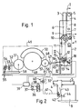
- Fig. 1 A cross section through a feed shaft according to the invention, with a connected card, shown semi-schematically.
- Fig. 2 A detail of the feed shaft of Fig. 1, shown in section I-I (Fig. 1).
- Fig. 3 The detail of Fig. 2, but with a further detail thereof in another Operating situation shown.
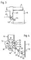
- Fig. 4 Another detail of the feed shaft, shown in section II-II (Fig. 5) and enlarged.
- Fig. 5 The detail of Fig. 4 shown in viewing direction III-III (Fig. 1).
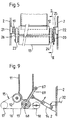
- Fig. 6 + 7 One variant of the feed shaft from Fig. 1.
- Fig. 8 The feed shaft of Fig. 7 in the viewing direction IV and in section V-V shown.
- a discharge head 3 and an exhaust air housing 4 are connected to a housing 2 of a feed shaft 1.
- the exhaust air housing 4 is connected to an exhaust pipe 5.
- an air separation shaft 6 is provided, from which a perforated plate 7 is adjacent, from the top downward, as viewed in FIG. 1, or in the direction of travel of the fiber flakes, below the separation head 3.
- the air separation shaft 6 receives a fiber flake-air mixture, which was conveyed into the air separation shaft 6 via the separation head 3.
- the fiber flakes remain in the air separation shaft, while the air through the perforated plate 7 in the exhaust air room 8 and from this through the exhaust air housing 4 into the exhaust pipe 5.
- feed rollers 9 and a dissolving roller 10 are provided, which discharge the fiber flakes in the air separation shaft 6, respectively. further dissolve and dispense into a feed chute 11.
- stationary discharge rollers are arranged for the discharge of the fiber flakes from the feed chute 11 so as to be rotatable about their axes of rotation.
- These stationary discharge rollers 12 are driven by a drive 15, which is indicated by dash-dotted lines and comprises a drive chain 16, a drive wheel 17 and a tension compensation wheel 18.
- the chain engages around the chain wheels 19 (FIG. 5) provided on the respective shaft of the discharge rollers in such a way that they rotate in the opposite direction of rotation.
- a sprocket is mounted on the shaft of the corresponding discharge roller at one end of the discharge rollers 12 and 13, which are connected to one another by means of a chain 20, so that the sprocket 19 connects the corresponding stationary discharge roller 12 transmitted torque can be transmitted to the movable discharge roller 13 by means of this chain 20.
- Both shafts of the stationary discharge rollers 12 have a sprocket 19.
- the stationary discharge rollers 12 are each by means of a rotary bearing 21 and 22 in the housing 2, while the movable discharge roller 13 is supported at both ends with its shaft in pivoting brackets 23 and 24 (only 24 is visible in FIG. 4), which in turn is pivotable from the shaft for the pivoting process the right discharge roller 12 (seen with a view of FIG. 1) are included.
- the shaft of this stationary roller is marked with 25.
- the swivel tabs 23 and 24 are rigidly connected to one another by means of a bracket 26, which in turn is pivotally connected to a pressure cylinder 14 by means of a swivel axis 27.
- the pressure cylinder itself is pivotally connected by means of a pivot axis 29 to a carrier 30 which is fixedly arranged on the housing 2 (see FIG. 4).
- the stationary discharge rollers 12 have a fixed distance A, while the operating distance between the movable discharge roller 13 and the opposite stationary discharge roller 12 is marked B, and generally corresponds to the distance which is caused by the compression of the fiber mat as a result of the pressure cylinder 14 generated force arises.
- This distance B is generally not rigid, but corresponds to the thickness of the fiber mat guided in between.
- the pressure cylinder 14 can be acted upon on one side Pressure cylinder with a spring (not shown) for the retracting movement of the cylinder piston 31.
- the pressure cylinder 14 is pressurized by means of a pressure line 32 and the pressure cylinder 14 is vented according to arrow 33 for the extension stroke. 1, the pressure line 32 is connected to an electrically controlled single-acting 4/2-way valve 34.
- the 4/2-way valve in turn is connected pneumatically by means of a line 36, to a compressed air source 37 and electrically by means of a line 38 to a controller 39.
- a pressure reducing valve 40 can be provided in the pressure line 32 in order to control the pressure for the pressure cylinder 14. Without this pressure reducing valve, the pressure in the pressure line 36 or in the compressed air source 37 must already be controlled, or the pressure cylinder 14 is selected in accordance with a given air pressure and a required force.
- a further pressure line 41 leads to a single-acting pressure cylinder 42, which closes an air flap 43 that can be closed off the perforated plate 7 if no flakes are conveyed into the air separator shaft 6.
- the pressure cylinder 42 is not connected to the air flap 43, since it must be pivotable in a predetermined range for operation.
- the flap is connected to a counterweight 44. The function of the flap is described in the article mentioned at the beginning and is therefore not mentioned further.
- Fig. 3 is the closed flap 43 and the piston rod of the pressure cylinder which is in contact therewith 42 shown.
- the bordering of the card 46 by means of dash-dotted lines is intended to express that the feed shaft 1 can also be connected to other spinning machines which further process a fiber mat.
- the known per se elements of the card 46 include a feed cylinder 47, driven by a drive 56, a Briseurwalze 48, driven by a drive 57, a spool with a revolving flat 50 and a doffer 51, a doffer 52, ei n nip roller pair 53, a Condenser 54 and a pair of scanning rollers 55, wherein, as can be seen in FIG. 1, elements 51, 52, 53 and 55 are driven by a common drive 58.
- control 39 can be understood to mean the switch-on function of the card drives shown, which in turn can be part of a comprehensive card control not described here.
- fiber flakes are passed through the separating head 3 into the air separation shaft 6 and from there conveyed into the feed shaft 11 by means of the feed roller 9 and the opening roller 10.
- the stationary discharge rollers 12 compress the fiber flakes of the feed chute 11 according to the distance A to a fiber mat, which is conveyed between the movable discharge roller 13 and the opposite stationary discharge roller 12 by means of these stationary discharge rollers 12 and is thereby pressed into an even more compressed fiber mat.
- This pressed fiber mat then passes onto the guide plate 45, and on this further into the card 46, ie to the feed roller 47.
- valve 39 is simultaneously changed over by the controller 39 so that the pressure line 32 is vented and the pressure lines 41 are supplied with pressure.
- the movable discharge roller 13 is moved back into the rest position in the pivoting direction W and on the other hand the pressure cylinder 42 closes the flap 43.
- Air movements are understood to mean the air flow from the exhaust air space 8 into the exhaust air housing 4.
- FIG. 6 shows a feed shaft 1.1, which is a variant of the feed shaft 1 of FIG. 1, in that a conveyor belt 59 comprises the movable discharge roller 13 and the associated stationary discharge roller 12, so that the fiber mat discharged from the two stationary discharge rollers 12 over the conveyor belt 59 is conveyed into the space with the distance B.
- the bracket 26 is designed in such a way that it overlaps the conveyor belt, which is shown in FIG. 4 with the conveyor belt 59 shown in dash-dotted lines.
- the drive chain 20 and the chain wheels (not shown) accommodating this chain can be dispensed with, since the movable discharge roller 13 can be driven by the stationary discharge roller 12 by means of a conveyor belt 59.
- the possibility of leaving the chain 20 and the associated sprockets and relieving the conveyor belt 59 of the drive function is also possible.
- FIG. 7 shows a feed shaft 1.2, which is a variant compared to the feed shaft 1 of FIG. 1 in that the feed shaft 11.1, viewed in the direction of FIG. 7, through a conveyor belt 60 and a conveyor belt 61 opposite thereto and is formed by two end walls 62 (only one end wall visible in FIG. 7) and shown in dashed lines in FIG. 7.
- the conveyor belt 60 is stationary and the conveyor belt 61 is arranged to be pivotable about the axis 63.
- the axis 63 is at the same time the axis for the upper deflection roller 64 (viewed in FIG. 7).
- the lower deflection rollers of the conveyor belts 60 and 61 are driven in the same way as the stationary drive rollers 12, but with the difference that the tension compensation wheel 18 of the drive 15 must be able to move the pivotable conveyor belt 61 record.
- the deflecting rollers of the conveyor belt 61 are connected to one another on their end faces by tabs 70 and 71 (FIG. 8), as is the case in FIGS. 5 shown as swivel tabs 23 and 24 tabs.
- the connecting tabs 70 and 71 mentioned are connected to one another by a bracket 28, analogously to the bracket 26 of FIG. 4, so that the pressure cylinder 14.1 can be pivotally attached to it.
- the pressure cylinder 14.1 is in turn pivotally attached to the housing 2 in the same way as the pressure cylinder 14 of FIG. 4 and connected to the pressure line 32.
- Fig. 8 shows on the left side of the conveyor belt 60 and 61, as seen in Fig. 8, a sprocket 19.1, which corresponds to the sprocket 19 of Fig. 5, which is provided on both lower shafts of the conveyor belts 60 and 61, and on the right side a chain 20.1 which, together with the corresponding sprockets (not shown), drive the upper deflection roller if this is not done by the conveyor belt itself.
- Fig. 8 only the stationary conveyor belt 60 is shown, it can be seen that the two free ends of the axis of the upper deflecting roller each in a bearing 65 fixed in the housing 2 and the shaft of the lower deflecting roller each in a bearing fixed in the housing 2 66 are rotatably mounted.
- the axis of the upper deflection roller of the conveyor belt 61 with the two free ends is likewise rotatably mounted in bearings provided in the housing 2 in a manner analogous to the axis of the deflection roller of the conveyor belt 60, while the shaft of the lower deflection roller of the conveyor belt 61 in the aforementioned, tabs 70 and 71 is rotatably mounted.
- FIG. 9 shows a further variant in that the right-hand stationary discharge roller 12 shown in FIG. 4 is omitted and the movable discharge roller 13 is pivotably mounted about the pivot axis 67.
- the shaft 68 of the movable discharge roller 13 is rotatably mounted in a swivel plate 69, which in turn is pivotally connected to the pressure cylinder 14.2, which in turn is arranged pivotably on the housing 2.
- the feeder shaft 11.1 is adapted in relation to the feeder shaft 11 in accordance with the swivel plate 69.
- the invention is not limited to the combination with a card, but can also be combined with other spinning machines into which a fiber mat has to be fed.
Landscapes
- Engineering & Computer Science (AREA)
- Textile Engineering (AREA)
- Preliminary Treatment Of Fibers (AREA)
Claims (10)
caractérisé par le fait que
le moyen d'évacuation mobile (13; 61) est maintenu d'une manière rotative au moins par un collier de fixation (23, 24; 70, 71) ou par une plaque (69), et le collier de fixation respectivement la plaque est maintenu d'une manière mobile, de même que le moyen d'évacuation mobile (13; 61) est mis en mouvement par un moyen d'entraînement (14; 14.1; 14.2) piloté par un moyen de commande (39) lors de l'arrêt des moyens d'évacuation (12, 13; 60; 61), depuis une position de marche dans laquelle celui-ci presse la nappe de fibres contre le moyen d'évacuation stationnaire (12; 60), dans une position de repos dans laquelle la nappe ne reçoit essentiellement aucune pression dans les moyens d'évacuation.
caractérisé par le fait que
que le moyen d'évacuation stationnaire (12) est formé par deux rouleaux d'évacuation (12) stationnaires, rotatifs et commandables, qui sont disposés avec une distance (A) prédéterminée l'un par rapport à l'autre, et que le moyen d'évacuation mobile (13) est un rouleau d'évacuation (13) commandable et pouvant être mis en mouvement d'approche et de recul contre respectivement depuis un des rouleaux d'évacuation stationnaires (12).
caractérisé par le fait que
le moyen d'évacuation mobile est un rouleau d'évacuation (13) oscillant vers le rouleau d'évacuation stationnaire (12).
caractérisé par le fait que
le rouleau d'évacuation oscillant (13) est relié avec un des rouleaux stationnaires (12) par une bande transporteuse (59) qui s'étend essentiellement sur la longueur complète des rouleaux, et que l'axe d'oscillation du rouleau d'évacuation mobile (12) est en même temps l'arbre (25) de ce rouleau d'évacuation stationnaire (12).
caractérisé par le fait que
le moyen d'évacuation stationnaire est une bande transporteuse stationnaire (60) et le moyen d'évacuation mobile (61) est une bande transporteuse oscillante, la bande transporteuse oscillante (61) comprenant un rouleau de déviation supérieur stationnaire (64) et un rouleau de déviation inférieur mobile, et que le rouleau de déviation mobile peut être mis en mouvement contre le rouleau de déviation inférieur stationnaire de la bande transporteuse stationnaire (60).
caractérisé par le fait que
le moyen d'entraînement est un cylindre électropneumatique mis en charge par un seul côté, avec remise en position par ressort.
caractérisé par le fait que
le moyen de commande est une vanne à 4/2 voies.
caractérisée par le fait que
la vanne à 4/2 voies est commandée en synchronisme avec une commande d'une machine de filature disposée en aval du silo d'alimentation, par exemple d'une carde (46), de telle manière que le moyen d'évacuation mobile (13; 61) est mû dans la position de repos, depuis la position de marche, lors de la mise à l'arrêt de la machine de filature (46).
caractérisé par le fait que
le silo d'alimentation (1) comprend un dispositif de remplissage pneumatique (3, 4, 5, 6) et un clapet d'air évacué (43), qui est ouvert et fermé par un cylindre électropneumatique (42) mis en charge par un seul côté, avec remise en position par ressort, et qui est actionné en synchronisme avec les moyens d'entraînement (14; 14.1; 14;2) du moyen d'évacuation mobile (13; 61) de telle manière que, lorsque le clapet (43) est fermé, le moyen d'évacuation mobile (13; 61) se trouve en position de repos.
caractérisé par le fait que
la pression utilisée pour charger le cylindre électropneumatique est maintenue à une valeur prédéterminée par une vanne de régulation de pression.
Applications Claiming Priority (2)
| Application Number | Priority Date | Filing Date | Title |
|---|---|---|---|
| CH1794/88 | 1988-05-11 | ||
| CH179488 | 1988-05-11 |
Publications (2)
| Publication Number | Publication Date |
|---|---|
| EP0341450A1 EP0341450A1 (fr) | 1989-11-15 |
| EP0341450B1 true EP0341450B1 (fr) | 1992-08-12 |
Family
ID=4218751
Family Applications (1)
| Application Number | Title | Priority Date | Filing Date |
|---|---|---|---|
| EP89106852A Expired - Lifetime EP0341450B1 (fr) | 1988-05-11 | 1989-04-17 | Dispositif pour décharger une natte de fibres d'une conduit d'alimentation |
Country Status (4)
| Country | Link |
|---|---|
| US (1) | US4993120A (fr) |
| EP (1) | EP0341450B1 (fr) |
| JP (1) | JPH01321919A (fr) |
| DE (1) | DE58902027D1 (fr) |
Cited By (1)
| Publication number | Priority date | Publication date | Assignee | Title |
|---|---|---|---|---|
| CN103603092A (zh) * | 2013-11-21 | 2014-02-26 | 山东省永信非织造材料有限公司 | 多仓给棉罗拉防疵装置 |
Families Citing this family (9)
| Publication number | Priority date | Publication date | Assignee | Title |
|---|---|---|---|---|
| DE4128929C2 (de) * | 1991-08-30 | 1996-05-02 | Spinnbau Gmbh | Vorrichtung zum Herstellen von Fasermaterial oder dergleichen mit vorgebbarem Vorlagegewicht |
| DE59302559D1 (de) * | 1992-04-01 | 1996-06-20 | Rieter Ag Maschf | Vorrichtung zum Regeln des Luftdurchsatzes in einem Luftkanal |
| US5915509A (en) * | 1996-04-05 | 1999-06-29 | Maschinenfabrik Rieter Ag | Method and device for regulating the sliver in a card |
| NL1010803C2 (nl) * | 1998-12-14 | 2000-06-19 | Inst Voor Agrotech Onderzoek | Transportinrichting. |
| US6553630B1 (en) | 2001-04-11 | 2003-04-29 | TRüTZSCHLER GMBH & CO. KG | Device for setting the distance between adjoining fiber clamping and fiber transfer locations in a fiber processing system |
| DE10118067A1 (de) * | 2001-04-11 | 2002-10-17 | Truetzschler Gmbh & Co Kg | Vorrichtung an einer Krempel oder Karde zur Vergleichmäßigung des Faserflors oder -bandes |
| DE102009009331A1 (de) * | 2009-02-17 | 2010-08-19 | TRüTZSCHLER GMBH & CO. KG | Vorrichtung an einer Spinnereivorbereitungsmaschine, insbesondere Karde, Krempel o. dgl. zum Einstellen eines Arbeitsspaltes |
| CN101724938B (zh) * | 2009-11-19 | 2011-09-28 | 太仓市万龙非织造工程有限公司 | 一种干法非织造前处理设备及设备上的罗拉组合输送装置 |
| US11230806B2 (en) * | 2018-12-28 | 2022-01-25 | Whirlpool Corporation | Fabric treating appliance with pelletizer |
Family Cites Families (9)
| Publication number | Priority date | Publication date | Assignee | Title |
|---|---|---|---|---|
| US159923A (en) * | 1875-02-16 | Improvement in feeding mechanisms for carding-iviachines | ||
| GB189315222A (en) * | 1893-08-09 | 1894-08-04 | William Henry Bailey | Improved Driving Chain for Cycles and other purposes. |
| FR1390285A (fr) * | 1964-01-04 | 1965-02-26 | Perfectionnements apportés aux cheminées de dépôt des machines à carder | |
| US3548461A (en) * | 1968-08-05 | 1970-12-22 | Ferdinand Reiterer | Textile fiber web forming and feeding apparatus and method |
| DE2004394C3 (de) * | 1970-01-31 | 1981-07-02 | Hergeth KG Maschinenfabrik und Apparatebau, 4408 Dülmen | Vorrichtung zum Regeln der Zufuhr von Fasergut beim Speisen von Karden u.dgl. |
| US4154485A (en) * | 1977-08-16 | 1979-05-15 | Fiber Controls Corporation | Web-former |
| US4510647A (en) * | 1982-10-13 | 1985-04-16 | Keller Alex J | Method and apparatus for controlling fiber density |
| EP0176668B1 (fr) * | 1984-09-18 | 1989-03-29 | Maschinenfabrik Rieter Ag | Disposition d'un puits d'alimentation pour matière fibreuse |
| US4657444A (en) * | 1985-07-24 | 1987-04-14 | Hergeth Hollingsworth Gmbh | Synchronized chute feed control system and method |
-
1989
- 1989-04-17 DE DE8989106852T patent/DE58902027D1/de not_active Expired - Lifetime
- 1989-04-17 EP EP89106852A patent/EP0341450B1/fr not_active Expired - Lifetime
- 1989-05-08 US US07/349,413 patent/US4993120A/en not_active Expired - Fee Related
- 1989-05-09 JP JP1114321A patent/JPH01321919A/ja active Pending
Cited By (2)
| Publication number | Priority date | Publication date | Assignee | Title |
|---|---|---|---|---|
| CN103603092A (zh) * | 2013-11-21 | 2014-02-26 | 山东省永信非织造材料有限公司 | 多仓给棉罗拉防疵装置 |
| CN103603092B (zh) * | 2013-11-21 | 2015-11-04 | 山东省永信非织造材料有限公司 | 多仓给棉罗拉防疵装置 |
Also Published As
| Publication number | Publication date |
|---|---|
| DE58902027D1 (de) | 1992-09-17 |
| US4993120A (en) | 1991-02-19 |
| JPH01321919A (ja) | 1989-12-27 |
| EP0341450A1 (fr) | 1989-11-15 |
Similar Documents
| Publication | Publication Date | Title |
|---|---|---|
| EP0341450B1 (fr) | Dispositif pour décharger une natte de fibres d'une conduit d'alimentation | |
| DE19548840A1 (de) | Strecke zum Doublieren und Verstrecken von Faserbändern | |
| DE4038838A1 (de) | Vorrichtung zum speisen von in flockenform befindlichem fasergut, z. b. baumwolle, chemiefasern u. dgl., zu verarbeitungsmaschinen | |
| EP0160165B1 (fr) | Procédé et dispositif pour la formation d'un enroulement d'ouate | |
| DE2403326C2 (de) | Vorrichtung an einer Karde oder Krempel zum Abnehmen und Zusammenfassen eines aus einem Lieferwerk der Karde oder Krempel austretenden Faserflors | |
| EP0922128A1 (fr) | Enrouleur a courroie | |
| DE19713225A1 (de) | Abreiss- und Lötvorrichtung an einer Kämmaschine | |
| EP0681980B1 (fr) | Dispositif pour pivoter un pot plat de va-et-vient d'une machine textile délivrant des mèches | |
| EP0922127B1 (fr) | Dispositif pour acheminer et comprimer une bande d'ouate | |
| DE19502240C2 (de) | Verfahren und Vorrichtung zum Einziehen einer Bedruckstoffbahn im Rollenrotationsdruck | |
| DE847718C (de) | Verfahren und Vorrichtung zum fortlaufenden Mischen von Textilfasern | |
| EP2767153A2 (fr) | Presse à balles rondes | |
| CH619273A5 (fr) | ||
| EP0965667B9 (fr) | Dispositif pour couper une mèche | |
| EP0593587B1 (fr) | Separation de rubans de fibres sur machines a filer preparatoires | |
| DE3338834A1 (de) | Oe-friktionsspinnmaschine | |
| DE10243295A1 (de) | Rundballenpresse | |
| DE4035025C2 (fr) | ||
| EP1917388A1 (fr) | Systeme d'alimentation en flocons | |
| DE19516655C2 (de) | Vorrichtung zum Zusammenführen von zwei in einer Rollenrotationsdruckmaschine geförderten Materialbahnen | |
| DE4433587A1 (de) | Landwirtschaftliche Wagenkolbenpresse | |
| EP0263786B1 (fr) | Procédé et installation de manipulation de matières en bandes en lots | |
| AT131423B (de) | Maschinenanlage zur automatischen Bandvereinigung im ununterbrochenen Betrieb. | |
| DD294848A5 (de) | Strangzufuehreinrichtung | |
| DE1510357C (de) | Streckwerk und Kalanderwalzenanordnung für Faserbänder |
Legal Events
| Date | Code | Title | Description |
|---|---|---|---|
| PUAI | Public reference made under article 153(3) epc to a published international application that has entered the european phase |
Free format text: ORIGINAL CODE: 0009012 |
|
| AK | Designated contracting states |
Kind code of ref document: A1 Designated state(s): CH DE FR GB IT LI |
|
| 17P | Request for examination filed |
Effective date: 19891205 |
|
| 17Q | First examination report despatched |
Effective date: 19910531 |
|
| GRAA | (expected) grant |
Free format text: ORIGINAL CODE: 0009210 |
|
| AK | Designated contracting states |
Kind code of ref document: B1 Designated state(s): CH DE FR GB IT LI |
|
| GBT | Gb: translation of ep patent filed (gb section 77(6)(a)/1977) | ||
| REF | Corresponds to: |
Ref document number: 58902027 Country of ref document: DE Date of ref document: 19920917 |
|
| ITF | It: translation for a ep patent filed | ||
| ET | Fr: translation filed | ||
| PLBE | No opposition filed within time limit |
Free format text: ORIGINAL CODE: 0009261 |
|
| STAA | Information on the status of an ep patent application or granted ep patent |
Free format text: STATUS: NO OPPOSITION FILED WITHIN TIME LIMIT |
|
| 26N | No opposition filed | ||
| PG25 | Lapsed in a contracting state [announced via postgrant information from national office to epo] |
Ref country code: FR Effective date: 19931229 |
|
| REG | Reference to a national code |
Ref country code: FR Ref legal event code: ST |
|
| PGFP | Annual fee paid to national office [announced via postgrant information from national office to epo] |
Ref country code: GB Payment date: 19960313 Year of fee payment: 8 |
|
| PGFP | Annual fee paid to national office [announced via postgrant information from national office to epo] |
Ref country code: DE Payment date: 19960314 Year of fee payment: 8 |
|
| PGFP | Annual fee paid to national office [announced via postgrant information from national office to epo] |
Ref country code: CH Payment date: 19960320 Year of fee payment: 8 |
|
| PG25 | Lapsed in a contracting state [announced via postgrant information from national office to epo] |
Ref country code: GB Effective date: 19970417 |
|
| PG25 | Lapsed in a contracting state [announced via postgrant information from national office to epo] |
Ref country code: LI Free format text: LAPSE BECAUSE OF NON-PAYMENT OF DUE FEES Effective date: 19970430 Ref country code: CH Free format text: LAPSE BECAUSE OF NON-PAYMENT OF DUE FEES Effective date: 19970430 |
|
| GBPC | Gb: european patent ceased through non-payment of renewal fee |
Effective date: 19970417 |
|
| REG | Reference to a national code |
Ref country code: CH Ref legal event code: PL |
|
| PG25 | Lapsed in a contracting state [announced via postgrant information from national office to epo] |
Ref country code: DE Free format text: LAPSE BECAUSE OF NON-PAYMENT OF DUE FEES Effective date: 19980101 |
|
| PG25 | Lapsed in a contracting state [announced via postgrant information from national office to epo] |
Ref country code: IT Free format text: LAPSE BECAUSE OF NON-PAYMENT OF DUE FEES;WARNING: LAPSES OF ITALIAN PATENTS WITH EFFECTIVE DATE BEFORE 2007 MAY HAVE OCCURRED AT ANY TIME BEFORE 2007. THE CORRECT EFFECTIVE DATE MAY BE DIFFERENT FROM THE ONE RECORDED. Effective date: 20050417 |