EP0341131B1 - Verfahren und Raum zur thermischen Behandlung mit einer Abkühlungsstufe - Google Patents
Verfahren und Raum zur thermischen Behandlung mit einer Abkühlungsstufe Download PDFInfo
- Publication number
- EP0341131B1 EP0341131B1 EP89401182A EP89401182A EP0341131B1 EP 0341131 B1 EP0341131 B1 EP 0341131B1 EP 89401182 A EP89401182 A EP 89401182A EP 89401182 A EP89401182 A EP 89401182A EP 0341131 B1 EP0341131 B1 EP 0341131B1
- Authority
- EP
- European Patent Office
- Prior art keywords
- space
- fan
- load
- treatment
- cooling
- Prior art date
- Legal status (The legal status is an assumption and is not a legal conclusion. Google has not performed a legal analysis and makes no representation as to the accuracy of the status listed.)
- Expired - Lifetime
Links
- 238000001816 cooling Methods 0.000 title claims description 20
- 238000000034 method Methods 0.000 title claims description 19
- 238000007669 thermal treatment Methods 0.000 title claims description 5
- 239000007789 gas Substances 0.000 claims description 29
- 239000012530 fluid Substances 0.000 claims description 23
- CURLTUGMZLYLDI-UHFFFAOYSA-N Carbon dioxide Chemical compound O=C=O CURLTUGMZLYLDI-UHFFFAOYSA-N 0.000 claims description 14
- 229910002092 carbon dioxide Inorganic materials 0.000 claims description 7
- 238000010411 cooking Methods 0.000 claims description 7
- 238000002347 injection Methods 0.000 claims description 7
- 239000007924 injection Substances 0.000 claims description 7
- 230000001954 sterilising effect Effects 0.000 claims description 7
- 238000004659 sterilization and disinfection Methods 0.000 claims description 7
- IJGRMHOSHXDMSA-UHFFFAOYSA-N Atomic nitrogen Chemical compound N#N IJGRMHOSHXDMSA-UHFFFAOYSA-N 0.000 claims description 6
- 239000007788 liquid Substances 0.000 claims description 6
- 238000007710 freezing Methods 0.000 claims description 3
- 229910052757 nitrogen Inorganic materials 0.000 claims description 3
- XLYOFNOQVPJJNP-UHFFFAOYSA-N water Substances O XLYOFNOQVPJJNP-UHFFFAOYSA-N 0.000 claims description 3
- 239000001569 carbon dioxide Substances 0.000 claims description 2
- 238000005507 spraying Methods 0.000 claims description 2
- 239000000284 extract Substances 0.000 claims 1
- 238000010438 heat treatment Methods 0.000 description 5
- 235000013305 food Nutrition 0.000 description 4
- 238000002156 mixing Methods 0.000 description 3
- 239000000203 mixture Substances 0.000 description 3
- 230000000694 effects Effects 0.000 description 2
- 238000005192 partition Methods 0.000 description 2
- 230000001105 regulatory effect Effects 0.000 description 2
- 238000011144 upstream manufacturing Methods 0.000 description 2
- 238000009825 accumulation Methods 0.000 description 1
- 230000003385 bacteriostatic effect Effects 0.000 description 1
- 239000010836 blood and blood product Substances 0.000 description 1
- 229940125691 blood product Drugs 0.000 description 1
- 230000009172 bursting Effects 0.000 description 1
- 229910052799 carbon Inorganic materials 0.000 description 1
- 239000003795 chemical substances by application Substances 0.000 description 1
- 239000002131 composite material Substances 0.000 description 1
- 239000002826 coolant Substances 0.000 description 1
- 238000010586 diagram Methods 0.000 description 1
- 238000007599 discharging Methods 0.000 description 1
- 230000008014 freezing Effects 0.000 description 1
- 239000013505 freshwater Substances 0.000 description 1
- 239000013529 heat transfer fluid Substances 0.000 description 1
- 238000000265 homogenisation Methods 0.000 description 1
- 239000005457 ice water Substances 0.000 description 1
- 239000000463 material Substances 0.000 description 1
- 239000002245 particle Substances 0.000 description 1
- 238000009928 pasteurization Methods 0.000 description 1
- 239000004033 plastic Substances 0.000 description 1
- 229920003023 plastic Polymers 0.000 description 1
- 238000004321 preservation Methods 0.000 description 1
- 239000007921 spray Substances 0.000 description 1
- 239000000126 substance Substances 0.000 description 1
- 230000008646 thermal stress Effects 0.000 description 1
- 230000009466 transformation Effects 0.000 description 1
- 238000009423 ventilation Methods 0.000 description 1
Images

Classifications
-
- F—MECHANICAL ENGINEERING; LIGHTING; HEATING; WEAPONS; BLASTING
- F25—REFRIGERATION OR COOLING; COMBINED HEATING AND REFRIGERATION SYSTEMS; HEAT PUMP SYSTEMS; MANUFACTURE OR STORAGE OF ICE; LIQUEFACTION SOLIDIFICATION OF GASES
- F25D—REFRIGERATORS; COLD ROOMS; ICE-BOXES; COOLING OR FREEZING APPARATUS NOT OTHERWISE PROVIDED FOR
- F25D3/00—Devices using other cold materials; Devices using cold-storage bodies
- F25D3/10—Devices using other cold materials; Devices using cold-storage bodies using liquefied gases, e.g. liquid air
- F25D3/102—Stationary cabinets
Definitions
- the present invention relates to an enclosure for thermal treatment as well as to a thermal treatment method comprising a cooling phase using cryogenic fluid.
- the present invention relates more particularly to a heat treatment enclosure for a load comprising at least one door, internal walls internally delimiting a load treatment space, and, externally, gas passages, a circulation fan for a gas fluid, disposed at one end of the space, extracting the gases from the space and discharging them into the passages towards the opposite end of the space, and means for injecting cryogenic fluid into the flow of gases arranged in the vicinity of the fan.
- a heat treatment enclosure for a load comprising at least one door, internal walls internally delimiting a load treatment space, and, externally, gas passages, a circulation fan for a gas fluid, disposed at one end of the space, extracting the gases from the space and discharging them into the passages towards the opposite end of the space, and means for injecting cryogenic fluid into the flow of gases arranged in the vicinity of the fan.
- loads of many products and objects are treated by cooking and / or sterilization then cooling.
- This treatment generally includes a hot sterilization or cooking step followed by cooling.
- the hot stage can be carried out with steam, which is very satisfactory in terms of processing speed and temperature uniformity within the products. Cooling is necessary for the subsequent handling of the objects in the case of sterilization, or for the preservation of the products in the case of food products.
- Cooling for economic reasons (speed) or for reasons of quality of the cooked products (in the case of food products) must be carried out according to precise and binding temperature profits over time.
- the cryogenic liquid is injected radially inwards into a chamber downstream of the fan, in an arrangement which is not very conducive to a good mixing of the cryogenic fluid with the circulation flow and tends to accumulate a significant part of the cryogenic fluid on the rear wall of the chamber and on the propeller shaft, with the associated drawbacks.
- the cryogenic fluid is injected into one of the recirculation passages in the direction towards the upstream chamber through which the fan shaft passes, in an arrangement having the same drawbacks as in the previous document, aggravated by the risk of fluid accumulation cryogenic not yet homogenized in the circulation flow on the upstream part of the load to be treated.
- the object of the present invention is to provide an enclosure and a heat treatment method guaranteeing efficient cooling kinetics whatever the charge to be cooled, by ensuring an extremely rapid and intimate mixing of the cryogenic fluid in the circulation flow, subjecting the charge. to a homogeneous flow of cold gas and limiting the thermal stresses imposed on the fan drive members.
- the injection means comprise at least one injection nozzle extending in the downstream part of the treatment space and projecting the cryogenic fluid onto the blades of the fan.
- the particles of cryogenic fluid are injected into the most turbulent zone and at the highest speed of the gas flow, the aerodynamic effect of the fan being supplemented by a mechanical effect of bursting and mixing of the jet of cryogenic fluid, the temperature homogenization of the circulation flow taking place regularly and uniformly in the return passages before coming to interest the load to be treated.
- Another subject of the present invention is a method of heat treatment of a charge in a treatment space in an enclosure of the type defined above, comprising a phase of cooling the charge by circulating through the charge of a gas flow sucked in at one end of the space by a fan and recirculated to the opposite end of the space and injection, into the gas flow, of a cryogenic fluid, characterized in that the cryogenic fluid is projected in the treatment space, downstream of the load, on the fan blades.
- the method comprises, before the cooling phase, a phase of sterilization or cooking of the load with steam.
- the process and the enclosures according to the invention can be implemented and used in the food industries, the pharmaceutical industries, in hospital pharmacy, in the chemical, plastics and composites industries, for the heat treatment of materials and in industry electronic.
- the treatment according to the invention is advantageously carried out in a single enclosure, so that all of the treatment, even when the latter comprises a final phase of deep-freezing, can be carried out without manipulation of one enclosure in another enclosure, and without handling or movement of the load in the enclosure where the cooling is perfectly homogeneous.
- the enclosure is generally cylindrical and heat-insulated, using steam as the heat transfer fluid intended to treat products in cooking, pasteurization, sterilization, or any other type of heat treatment, followed by cooling.
- the enclosure is of the autoclave type, capable of working under pressure during the entire treatment.
- the cylindrical enclosure 1 with heat-insulated walls capable of withstanding an overpressure comprises a door 2 .
- a load 3 of products to be treated is placed in the treatment space 4 delimited by the walls 5.5 ′ of the enclosure 1 , the partitions 6.6 ′ , the door 2 and the truncated cone disposed at the end of the enclosure opposite door 2 .
- the partitions 6,6 ′ and the cone 7 delimit passages 9,9 ′, 9 ⁇ .
- the fan 8 is capable of sucking the gas flow out of the treatment space 4 by the cone 7 .
- the opening 10 of the truncated cone 7 is opposite the fan 8 .
- the wall of the enclosure 1 is crossed near the fan 8 by at least one pipe 11 for supplying cryogenic fluid provided inside the enclosure 1 with a spray nozzle 12 directing the sprayed fluid towards the fan blades 13 .
- FIG. 1 Three nozzles are provided, as shown in FIG. 1 where a pipe 14 provided with a valve 15 makes it possible to distribute the cryogenic fluid coming from a reservoir not shown in three nozzles, but only one nozzle 12 is shown in detail. The number of nozzles depends on the capacity of the autoclave.
- a gas discharge orifice 16 is also provided in the wall 5 of the enclosure.
- the evacuation of gases is controlled by a valve 17 .
- the nozzle 12 can be a nozzle for spraying carbon dioxide or liquid nitrogen.
- the fan 8 When the fan 8 is operating, it circulates the gases as indicated in the figures by the arrows. The gas flow passes through the load 3 placed in the treatment space in the direction of the fan 8 which flows back towards the space 9 ⁇ . During this passage through the charge, it heats up giving its frigories. The cryogenic fluid injected by the nozzle (s) on the blades is refluxed with the gas heated in the space 9 ⁇ . In space 9 ⁇ , the mixture of gas and the cryogenic fluid supply recirculates through passages 9 and 9 ′ towards the opposite end of the autoclave, and crosses the load in the direction of the fan.
- the method according to the invention can prohibit any contact between the gas and the load during the recirculation.
- the pressure is regulated by the valve 17 closing the orifice 16 for the gas outlet.
- the orifice 16 is placed as close as possible to the end of the load, and if possible after the load on the side of the fan.
- the fan serves as a "flow or ventilated atmosphere + intake” mixer and delivers a homogeneous gas in temperature on its periphery.
- the cryogenic fluid and the flow thus mix perfectly during their passage through the space 9 ⁇ and the passages 9 and 9 ′ before passing through the charge.
- the arrangement of the nozzle in the treatment space 4 and not in the space 9 ⁇ has an advantage because the propeller shaft is protected, since it is located in an area not interested in ventilation.
- the orientation of the nozzle and its positioning in the autoclave, preferably near the fan allow when the solenoid valve opens a total transformation of the liquid CO2 into gas phase by delivering the maximum of frigories.
- the nozzle directs the jet of CO2 towards the "reaction" propeller for ventilating the autoclave so as to almost instantaneously mix the supply of CO2 with the ventilated atmosphere.
- the pressure in the autoclave can be regulated.
- liquid nitrogen can be used.
- the method according to the invention can be adapted to many types of treatment, both cooking and cooling of packaged foodstuffs or the sterilization and cooling of objects for the pharmaceutical industry and the treatment of blood products in bags. .
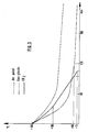
- the temperature must drop from a cooking temperature of the order of 60 ° to 90 ° C, in less than two hours, to a temperature of 10 ° C at its core.
- This profile can be respected with CO2 for example, as it appears on figure 3 , in a sure way (3 ° C reached) and faster than with forced air (cooled on finned exchanger by fresh water in circulation ) or sprayed 2 ° C ice water.
- An advantage of the process according to the invention appears when consumable products packaged under gas are cooked and then cooled. Indeed, it is then important that the pressure remains relatively constant during the entire treatment in the enclosure, especially for the appearance of the product.
- the pressure profile is easily controllable when all the treatment is carried out under cold gas or even hot then cold.
- the method according to the invention also comprises, or as a cold step, the freezing of the products.
- CO2 in particular has an advantageous bacteriostatic effect compared to water or air.
Landscapes
- Engineering & Computer Science (AREA)
- Chemical & Material Sciences (AREA)
- Combustion & Propulsion (AREA)
- Physics & Mathematics (AREA)
- Mechanical Engineering (AREA)
- Thermal Sciences (AREA)
- General Engineering & Computer Science (AREA)
- Food Preservation Except Freezing, Refrigeration, And Drying (AREA)
- Freezing, Cooling And Drying Of Foods (AREA)
- Apparatus For Disinfection Or Sterilisation (AREA)
Claims (10)
- Behälter für die thermische Behandlung einer Charge mit mindestens einer Tür (2), Innenwänden (6, 6', 7), die innenseitig einen Raum (4) zur Behandlung der Charge und außenseitig Gasdurchlässe (9, 9') begrenzen, einem Gebläse (8) zum Erzeugen einer Gaszirkulation, das an einem ersten Ende des Raums (4) angeordnet ist, die Gase aus dem Raum abzieht und sie in die Durchlässe (9, 9') in Richtung des gegenüberliegenden zweiten Endes des Raums fördert, und mit einer in der Nähe des Gebläses angebrachten Einrichtung (12) zur Injektion eines Tieftemperaturfluids in den Gasfluß, dadurch gekennzeichnet, daß die Einrichtung zur Injektion mindestens eine Injektionsdüse (12) aufweist, die sich in den stromabseitigen Teil des Behandlungsraums erstreckt und das Tieftemperaturfluid auf die Flügel des Gebläses (8) ausstößt.
- Behälter nach Anspruch 1, gekennzeichnet durch eine einstellbare Gasevakuierungseinrichtung (16, 17), die in der Nähe des ersten Endes des Behandlungsraums (4) angeordnet ist.
- Behälter nach Anspruch 1 oder 2, gekennzeichnet durch wärmeisolierte und druckfeste Außenwände.
- Verfahren zur thermischen Behandlung einer sich in einem Behandlungsraum (4) in einem Behälter (1) befindenden Charge (3), das eine Phase zur Kühlung der Charge durch Umwälzung eines an einem Ende des Raums (4) mittels eines Gebläses (8) angesaugten, über die Charge geleiteten und in Richtung des entgegengesetzten Endes des Raums zurückgeführten Gasflusses und Injektion eines Tieftemperaturbehandlungsfluids in den Gasfluß umfaßt, dadurch gekennzeichnet, daß das Tieftemperaturfluid während der Kühlphase in den Raum (4) stromabwärts der Charge auf die Flügel des Gebläses (8) ausgestoßen wird.
- Verfahren nach Anspruch 4, dadurch gekennzeichnet, daß der Druck in dem Behälter zumindest während der Kühlphase gesteuert wird.
- Verfahren nach Anspruch 5, dadurch gekennzeichnet, daß die Kühlphase einen ersten Schritt der Kühlung durch Gebläseluft oder durch Zerstäubung von oder Berieselung mit Wasser aufweist.
- Verfahren nach einem der Ansprüche 4 bis 6, dadurch gekennzeichnet, daß es vor der Kühlphase eine Phase der Sterilisation oder Erhitzung der Charge mittels Dampf umfaßt.
- Verfahren nach einem der Ansprüche 4 bis 7, dadurch gekennzeichnet, daß es des weiteren einen Tiefkühlschritt umfaßt.
- Verfahren nach Anspruch 7 oder 8, dadurch gekennzeichnet, daß die gesamte Behandlung unter Druck durchgeführt wird.
- Verfahren nach einem der Ansprüche 4 bis 9, dadurch gekennzeichnet, daß das Tieftemperaturfluid Kohlendioxid oder flüssiger Stickstoff ist.
Applications Claiming Priority (2)
| Application Number | Priority Date | Filing Date | Title |
|---|---|---|---|
| FR8805879 | 1988-05-02 | ||
| FR8805879A FR2630818B1 (fr) | 1988-05-02 | 1988-05-02 | Enceinte et procede de traitement thermique comportant une phase de refroidissement |
Publications (2)
| Publication Number | Publication Date |
|---|---|
| EP0341131A1 EP0341131A1 (de) | 1989-11-08 |
| EP0341131B1 true EP0341131B1 (de) | 1993-09-29 |
Family
ID=9365908
Family Applications (1)
| Application Number | Title | Priority Date | Filing Date |
|---|---|---|---|
| EP89401182A Expired - Lifetime EP0341131B1 (de) | 1988-05-02 | 1989-04-26 | Verfahren und Raum zur thermischen Behandlung mit einer Abkühlungsstufe |
Country Status (7)
| Country | Link |
|---|---|
| US (2) | US4878353A (de) |
| EP (1) | EP0341131B1 (de) |
| AU (1) | AU632746B2 (de) |
| CA (1) | CA1332111C (de) |
| DE (1) | DE68909484T2 (de) |
| ES (1) | ES2044162T3 (de) |
| FR (1) | FR2630818B1 (de) |
Families Citing this family (7)
| Publication number | Priority date | Publication date | Assignee | Title |
|---|---|---|---|---|
| US5879732A (en) * | 1996-09-10 | 1999-03-09 | Boc Group, Inc. | Food processing method |
| JP3346716B2 (ja) * | 1997-02-14 | 2002-11-18 | 東京エレクトロン株式会社 | 基板冷却方法および基板冷却装置 |
| US7905154B2 (en) * | 2004-11-29 | 2011-03-15 | Jones Jr Arthur T | Apparatus and method of contaminant detection for food industry |
| CN101842629A (zh) * | 2007-08-28 | 2010-09-22 | 气体产品与化学公司 | 用于在低温构件上提供无冷凝液和无霜表面的设备和方法 |
| US9587873B2 (en) * | 2012-03-27 | 2017-03-07 | Global Cooling, Inc. | Energy efficient biological freezer with vial management system |
| CN106766514A (zh) * | 2016-12-02 | 2017-05-31 | 青岛海尔股份有限公司 | 冷藏冷冻设备 |
| JP7674158B2 (ja) * | 2021-05-31 | 2025-05-09 | 古河機械金属株式会社 | 硫化リチウム製造装置および硫化リチウムの製造方法 |
Family Cites Families (16)
| Publication number | Priority date | Publication date | Assignee | Title |
|---|---|---|---|---|
| DE1802699A1 (de) * | 1967-10-13 | 1969-08-14 | J & E Hall Ltd | Gefrier- oder Kuehlanlage |
| US3536132A (en) * | 1968-09-27 | 1970-10-27 | Universal Oil Prod Co | Freezer-oven unit |
| US4399658A (en) * | 1978-02-08 | 1983-08-23 | Safeway Stores, Incorporated | Refrigeration system with carbon dioxide injector |
| US4237700A (en) * | 1979-04-20 | 1980-12-09 | Airco, Inc. | Methods and apparatus for providing refrigeration |
| US4304293A (en) * | 1979-06-18 | 1981-12-08 | Helmholtz-Institut Fur Biomedizinische Technik | Process and apparatus for freezing living cells |
| FR2462673A1 (fr) * | 1979-08-03 | 1981-02-13 | Carboxyque Francaise | Enceinte de refrigeration |
| CA1128329A (en) * | 1981-04-24 | 1982-07-27 | Douglas Hurst | Cryogenic treatment of materials |
| FR2525747A2 (fr) * | 1981-05-29 | 1983-10-28 | Keller Jean Paul | Procede de surgelation et de conditionnement de produits individuels, et dispositif pour la mise en oeuvre de ce procede |
| FR2526927A1 (fr) * | 1982-05-14 | 1983-11-18 | Anhydride Carbonique Ind | Cellule de surgelation et de refroidissement |
| FR2530004A1 (fr) * | 1982-07-07 | 1984-01-13 | Air Liquide | Dispositif de congelation de produits biologiques conditionnes en tubes, ampoules ou paillettes |
| US4481782A (en) * | 1983-01-25 | 1984-11-13 | The Boc Group, Inc. | Methods and apparatus for refrigerating products |
| US4475351A (en) * | 1983-08-09 | 1984-10-09 | Air Products And Chemicals, Inc. | Dual-flow cryogenic freezer |
| US4644754A (en) * | 1984-01-11 | 1987-02-24 | Carboxyque Francaise | Process and apparatus for cooling a charge of products |
| FR2558337B1 (fr) * | 1984-01-19 | 1986-05-02 | Air Liquide | Dispositif de congelation de produits biologiques conditionnes en paillettes |
| EP0170580B1 (de) * | 1984-07-12 | 1988-06-01 | Carboxyque Francaise | Verfahren und Vorrichtung zur Kühlung einer Produktladung |
| FR2593593B1 (fr) * | 1986-01-28 | 1988-08-26 | Carboxyque Francaise | Procede et appareil pour realiser dans un objet mou une cavite cylindrique |
-
1988
- 1988-05-02 FR FR8805879A patent/FR2630818B1/fr not_active Expired - Fee Related
- 1988-09-09 US US07/244,516 patent/US4878353A/en not_active Ceased
-
1989
- 1989-04-26 ES ES89401182T patent/ES2044162T3/es not_active Expired - Lifetime
- 1989-04-26 DE DE89401182T patent/DE68909484T2/de not_active Expired - Lifetime
- 1989-04-26 EP EP89401182A patent/EP0341131B1/de not_active Expired - Lifetime
- 1989-05-01 AU AU33888/89A patent/AU632746B2/en not_active Ceased
- 1989-05-01 CA CA000598309A patent/CA1332111C/fr not_active Expired - Fee Related
-
1990
- 1990-04-12 US US07/507,883 patent/USRE33852E/en not_active Expired - Lifetime
Also Published As
| Publication number | Publication date |
|---|---|
| FR2630818A1 (fr) | 1989-11-03 |
| ES2044162T3 (es) | 1994-01-01 |
| US4878353A (en) | 1989-11-07 |
| FR2630818B1 (fr) | 1990-09-14 |
| EP0341131A1 (de) | 1989-11-08 |
| DE68909484T2 (de) | 1994-05-11 |
| USRE33852E (en) | 1992-03-24 |
| AU3388889A (en) | 1989-11-02 |
| DE68909484D1 (de) | 1993-11-04 |
| AU632746B2 (en) | 1993-01-14 |
| CA1332111C (fr) | 1994-09-27 |
Similar Documents
| Publication | Publication Date | Title |
|---|---|---|
| US3214928A (en) | Method and apparatus for freezing food products | |
| EP0445286B1 (de) | Temperatur-geregelte nahrungsmittelbehandlungsvorrichtung und verfahren | |
| EP0341131B1 (de) | Verfahren und Raum zur thermischen Behandlung mit einer Abkühlungsstufe | |
| US4543263A (en) | Heating and cooling foods at high pressure in a continuous sterilization system | |
| US20140013962A1 (en) | Deposition of materials for edible solid freeform fabrication | |
| EP3166421B1 (de) | Anlage zum auftauen oder temperieren eingefrorener lebensmittel | |
| EP0309319A1 (de) | Anlage zum Kühlen eines kontinuierlich extrudierten Produktes | |
| EP0138688B1 (de) | Autoklav und Verfahren zur Sterilisation | |
| AU715465B2 (en) | Cooling apparatus | |
| CA2080202C (en) | Wheel type freezer and method for rapid, low temperature freezing | |
| US4084387A (en) | Apparatus and process for refrigerating materials | |
| EP0155886A1 (de) | Verfahren und Vorrichtung zur Kühlung eines viskosen Produktes, insbesondere eines Nahrungsmittels | |
| EP0297010B1 (de) | Autoklav | |
| JP7114627B2 (ja) | 熱過敏性流体をポンプ送りするためのポンプ | |
| EP0601952B1 (de) | Verfahren zur thermischen Behandlung von Nahrungsmitteln, insbesondere zum Kochen von Gemüse und Anlage zur Durchführung des Verfahrens | |
| FR2735748A1 (fr) | Procede et installation de conditionnement aseptique de produits alimentaires frais dans des emballages souples ou rigides | |
| JP5495865B2 (ja) | 凍結乾燥機 | |
| FR3016812A1 (fr) | Systeme de traitement thermique d'articles | |
| EP1772669A2 (de) | Einrichtung zum Heizen und Erzeugen von Dampf für Garofen | |
| CA1054814A (en) | Apparatus for refrigerating materials | |
| FR3136145A1 (fr) | Installation de pasteurisation par micro-onde intégrant un système de refroidissement par ventilation | |
| JP2004054569A (ja) | 容器入り飲料の加熱装置及びこれを用いた自動販売機 | |
| FR2637966A1 (fr) | Dispositif de conditionnement d'air interieur | |
| FR2614977A1 (fr) | Procede de sechage des produits thermosensibles et appareil pour sa mise en oeuvre | |
| JPS59198961A (ja) | 冷凍食品の製法および装置 |
Legal Events
| Date | Code | Title | Description |
|---|---|---|---|
| PUAI | Public reference made under article 153(3) epc to a published international application that has entered the european phase |
Free format text: ORIGINAL CODE: 0009012 |
|
| 17P | Request for examination filed |
Effective date: 19890429 |
|
| AK | Designated contracting states |
Kind code of ref document: A1 Designated state(s): BE CH DE ES FR IT LI LU NL SE |
|
| 17Q | First examination report despatched |
Effective date: 19900913 |
|
| GRAA | (expected) grant |
Free format text: ORIGINAL CODE: 0009210 |
|
| AK | Designated contracting states |
Kind code of ref document: B1 Designated state(s): BE CH DE ES FR IT LI LU NL SE |
|
| REF | Corresponds to: |
Ref document number: 68909484 Country of ref document: DE Date of ref document: 19931104 |
|
| ITF | It: translation for a ep patent filed | ||
| REG | Reference to a national code |
Ref country code: ES Ref legal event code: FG2A Ref document number: 2044162 Country of ref document: ES Kind code of ref document: T3 |
|
| EPTA | Lu: last paid annual fee | ||
| PLBE | No opposition filed within time limit |
Free format text: ORIGINAL CODE: 0009261 |
|
| STAA | Information on the status of an ep patent application or granted ep patent |
Free format text: STATUS: NO OPPOSITION FILED WITHIN TIME LIMIT |
|
| 26N | No opposition filed | ||
| EAL | Se: european patent in force in sweden |
Ref document number: 89401182.4 |
|
| PGFP | Annual fee paid to national office [announced via postgrant information from national office to epo] |
Ref country code: CH Payment date: 20020314 Year of fee payment: 14 |
|
| PGFP | Annual fee paid to national office [announced via postgrant information from national office to epo] |
Ref country code: LU Payment date: 20020319 Year of fee payment: 14 Ref country code: SE Payment date: 20020319 Year of fee payment: 14 |
|
| PG25 | Lapsed in a contracting state [announced via postgrant information from national office to epo] |
Ref country code: LU Free format text: LAPSE BECAUSE OF NON-PAYMENT OF DUE FEES Effective date: 20030426 |
|
| PG25 | Lapsed in a contracting state [announced via postgrant information from national office to epo] |
Ref country code: SE Free format text: LAPSE BECAUSE OF NON-PAYMENT OF DUE FEES Effective date: 20030427 |
|
| PG25 | Lapsed in a contracting state [announced via postgrant information from national office to epo] |
Ref country code: LI Free format text: LAPSE BECAUSE OF NON-PAYMENT OF DUE FEES Effective date: 20030430 Ref country code: CH Free format text: LAPSE BECAUSE OF NON-PAYMENT OF DUE FEES Effective date: 20030430 |
|
| EUG | Se: european patent has lapsed | ||
| REG | Reference to a national code |
Ref country code: CH Ref legal event code: PL |
|
| REG | Reference to a national code |
Ref country code: FR Ref legal event code: TP |
|
| PGFP | Annual fee paid to national office [announced via postgrant information from national office to epo] |
Ref country code: ES Payment date: 20080418 Year of fee payment: 20 Ref country code: FR Payment date: 20080313 Year of fee payment: 20 Ref country code: DE Payment date: 20080320 Year of fee payment: 20 |
|
| PGFP | Annual fee paid to national office [announced via postgrant information from national office to epo] |
Ref country code: IT Payment date: 20080329 Year of fee payment: 20 Ref country code: BE Payment date: 20080416 Year of fee payment: 20 |
|
| PGFP | Annual fee paid to national office [announced via postgrant information from national office to epo] |
Ref country code: NL Payment date: 20080325 Year of fee payment: 20 |
|
| BE20 | Be: patent expired |
Owner name: SOC. NOUVELLE DES ETS J. *LAGARDE Effective date: 20090426 Owner name: *CARBOXYQUE FRANCAISE Effective date: 20090426 |
|
| PG25 | Lapsed in a contracting state [announced via postgrant information from national office to epo] |
Ref country code: NL Free format text: LAPSE BECAUSE OF EXPIRATION OF PROTECTION Effective date: 20090426 |
|
| REG | Reference to a national code |
Ref country code: ES Ref legal event code: FD2A Effective date: 20090427 |
|
| NLV7 | Nl: ceased due to reaching the maximum lifetime of a patent |
Effective date: 20090426 |
|
| PG25 | Lapsed in a contracting state [announced via postgrant information from national office to epo] |
Ref country code: ES Free format text: LAPSE BECAUSE OF EXPIRATION OF PROTECTION Effective date: 20090427 |