EP0340873B1 - Mischvorrichtung mit Verteilungsmischwirkung für eine Schneckenpresse, eine Spritzgiessmaschine und dergleichen - Google Patents
Mischvorrichtung mit Verteilungsmischwirkung für eine Schneckenpresse, eine Spritzgiessmaschine und dergleichen Download PDFInfo
- Publication number
- EP0340873B1 EP0340873B1 EP89201132A EP89201132A EP0340873B1 EP 0340873 B1 EP0340873 B1 EP 0340873B1 EP 89201132 A EP89201132 A EP 89201132A EP 89201132 A EP89201132 A EP 89201132A EP 0340873 B1 EP0340873 B1 EP 0340873B1
- Authority
- EP
- European Patent Office
- Prior art keywords
- mixing
- rotor
- mixer device
- ring
- stator
- Prior art date
- Legal status (The legal status is an assumption and is not a legal conclusion. Google has not performed a legal analysis and makes no representation as to the accuracy of the status listed.)
- Expired - Lifetime
Links
- 238000001746 injection moulding Methods 0.000 title claims abstract description 15
- 239000000463 material Substances 0.000 description 13
- 239000011345 viscous material Substances 0.000 description 4
- 238000004519 manufacturing process Methods 0.000 description 3
- 230000004323 axial length Effects 0.000 description 1
- 239000004927 clay Substances 0.000 description 1
- 230000006835 compression Effects 0.000 description 1
- 238000007906 compression Methods 0.000 description 1
- 238000010276 construction Methods 0.000 description 1
- 230000007423 decrease Effects 0.000 description 1
- 230000007850 degeneration Effects 0.000 description 1
- 238000005516 engineering process Methods 0.000 description 1
- 230000002349 favourable effect Effects 0.000 description 1
- 238000002347 injection Methods 0.000 description 1
- 239000007924 injection Substances 0.000 description 1
- 235000013310 margarine Nutrition 0.000 description 1
- 239000003264 margarine Substances 0.000 description 1
- 239000004033 plastic Substances 0.000 description 1
- 229920003023 plastic Polymers 0.000 description 1
- 239000005060 rubber Substances 0.000 description 1
- 238000010008 shearing Methods 0.000 description 1
- 239000000344 soap Substances 0.000 description 1
Images

Classifications
-
- B—PERFORMING OPERATIONS; TRANSPORTING
- B29—WORKING OF PLASTICS; WORKING OF SUBSTANCES IN A PLASTIC STATE IN GENERAL
- B29C—SHAPING OR JOINING OF PLASTICS; SHAPING OF MATERIAL IN A PLASTIC STATE, NOT OTHERWISE PROVIDED FOR; AFTER-TREATMENT OF THE SHAPED PRODUCTS, e.g. REPAIRING
- B29C45/00—Injection moulding, i.e. forcing the required volume of moulding material through a nozzle into a closed mould; Apparatus therefor
- B29C45/17—Component parts, details or accessories; Auxiliary operations
- B29C45/46—Means for plasticising or homogenising the moulding material or forcing it into the mould
- B29C45/58—Details
- B29C45/581—Devices for influencing the material flow, e.g. "torpedo constructions" or mixing devices
-
- B—PERFORMING OPERATIONS; TRANSPORTING
- B29—WORKING OF PLASTICS; WORKING OF SUBSTANCES IN A PLASTIC STATE IN GENERAL
- B29B—PREPARATION OR PRETREATMENT OF THE MATERIAL TO BE SHAPED; MAKING GRANULES OR PREFORMS; RECOVERY OF PLASTICS OR OTHER CONSTITUENTS OF WASTE MATERIAL CONTAINING PLASTICS
- B29B7/00—Mixing; Kneading
- B29B7/30—Mixing; Kneading continuous, with mechanical mixing or kneading devices
- B29B7/34—Mixing; Kneading continuous, with mechanical mixing or kneading devices with movable mixing or kneading devices
- B29B7/38—Mixing; Kneading continuous, with mechanical mixing or kneading devices with movable mixing or kneading devices rotary
- B29B7/40—Mixing; Kneading continuous, with mechanical mixing or kneading devices with movable mixing or kneading devices rotary with single shaft
- B29B7/42—Mixing; Kneading continuous, with mechanical mixing or kneading devices with movable mixing or kneading devices rotary with single shaft with screw or helix
- B29B7/421—Mixing; Kneading continuous, with mechanical mixing or kneading devices with movable mixing or kneading devices rotary with single shaft with screw or helix with screw and additionally other mixing elements on the same shaft, e.g. paddles, discs, bearings, rotor blades of the Banbury type
-
- B—PERFORMING OPERATIONS; TRANSPORTING
- B29—WORKING OF PLASTICS; WORKING OF SUBSTANCES IN A PLASTIC STATE IN GENERAL
- B29B—PREPARATION OR PRETREATMENT OF THE MATERIAL TO BE SHAPED; MAKING GRANULES OR PREFORMS; RECOVERY OF PLASTICS OR OTHER CONSTITUENTS OF WASTE MATERIAL CONTAINING PLASTICS
- B29B7/00—Mixing; Kneading
- B29B7/30—Mixing; Kneading continuous, with mechanical mixing or kneading devices
- B29B7/34—Mixing; Kneading continuous, with mechanical mixing or kneading devices with movable mixing or kneading devices
- B29B7/38—Mixing; Kneading continuous, with mechanical mixing or kneading devices with movable mixing or kneading devices rotary
- B29B7/40—Mixing; Kneading continuous, with mechanical mixing or kneading devices with movable mixing or kneading devices rotary with single shaft
- B29B7/42—Mixing; Kneading continuous, with mechanical mixing or kneading devices with movable mixing or kneading devices rotary with single shaft with screw or helix
- B29B7/422—Mixing; Kneading continuous, with mechanical mixing or kneading devices with movable mixing or kneading devices rotary with single shaft with screw or helix with screw sections co-operating, e.g. intermeshing, with elements on the wall of the surrounding casing
- B29B7/423—Mixing; Kneading continuous, with mechanical mixing or kneading devices with movable mixing or kneading devices rotary with single shaft with screw or helix with screw sections co-operating, e.g. intermeshing, with elements on the wall of the surrounding casing and oscillating axially
-
- B—PERFORMING OPERATIONS; TRANSPORTING
- B29—WORKING OF PLASTICS; WORKING OF SUBSTANCES IN A PLASTIC STATE IN GENERAL
- B29B—PREPARATION OR PRETREATMENT OF THE MATERIAL TO BE SHAPED; MAKING GRANULES OR PREFORMS; RECOVERY OF PLASTICS OR OTHER CONSTITUENTS OF WASTE MATERIAL CONTAINING PLASTICS
- B29B7/00—Mixing; Kneading
- B29B7/30—Mixing; Kneading continuous, with mechanical mixing or kneading devices
- B29B7/34—Mixing; Kneading continuous, with mechanical mixing or kneading devices with movable mixing or kneading devices
- B29B7/38—Mixing; Kneading continuous, with mechanical mixing or kneading devices with movable mixing or kneading devices rotary
- B29B7/40—Mixing; Kneading continuous, with mechanical mixing or kneading devices with movable mixing or kneading devices rotary with single shaft
- B29B7/42—Mixing; Kneading continuous, with mechanical mixing or kneading devices with movable mixing or kneading devices rotary with single shaft with screw or helix
- B29B7/428—Parts or accessories, e.g. casings, feeding or discharging means
-
- B—PERFORMING OPERATIONS; TRANSPORTING
- B29—WORKING OF PLASTICS; WORKING OF SUBSTANCES IN A PLASTIC STATE IN GENERAL
- B29B—PREPARATION OR PRETREATMENT OF THE MATERIAL TO BE SHAPED; MAKING GRANULES OR PREFORMS; RECOVERY OF PLASTICS OR OTHER CONSTITUENTS OF WASTE MATERIAL CONTAINING PLASTICS
- B29B7/00—Mixing; Kneading
- B29B7/30—Mixing; Kneading continuous, with mechanical mixing or kneading devices
- B29B7/58—Component parts, details or accessories; Auxiliary operations
- B29B7/60—Component parts, details or accessories; Auxiliary operations for feeding, e.g. end guides for the incoming material
-
- B—PERFORMING OPERATIONS; TRANSPORTING
- B29—WORKING OF PLASTICS; WORKING OF SUBSTANCES IN A PLASTIC STATE IN GENERAL
- B29B—PREPARATION OR PRETREATMENT OF THE MATERIAL TO BE SHAPED; MAKING GRANULES OR PREFORMS; RECOVERY OF PLASTICS OR OTHER CONSTITUENTS OF WASTE MATERIAL CONTAINING PLASTICS
- B29B7/00—Mixing; Kneading
- B29B7/74—Mixing; Kneading using other mixers or combinations of mixers, e.g. of dissimilar mixers ; Plant
- B29B7/7471—Mixers in which the mixing takes place at the inlet of a mould, e.g. mixing chambers situated in the mould opening
-
- B—PERFORMING OPERATIONS; TRANSPORTING
- B29—WORKING OF PLASTICS; WORKING OF SUBSTANCES IN A PLASTIC STATE IN GENERAL
- B29C—SHAPING OR JOINING OF PLASTICS; SHAPING OF MATERIAL IN A PLASTIC STATE, NOT OTHERWISE PROVIDED FOR; AFTER-TREATMENT OF THE SHAPED PRODUCTS, e.g. REPAIRING
- B29C48/00—Extrusion moulding, i.e. expressing the moulding material through a die or nozzle which imparts the desired form; Apparatus therefor
- B29C48/25—Component parts, details or accessories; Auxiliary operations
- B29C48/36—Means for plasticising or homogenising the moulding material or forcing it through the nozzle or die
- B29C48/395—Means for plasticising or homogenising the moulding material or forcing it through the nozzle or die using screws surrounded by a cooperating barrel, e.g. single screw extruders
- B29C48/45—Axially movable screws
-
- B—PERFORMING OPERATIONS; TRANSPORTING
- B29—WORKING OF PLASTICS; WORKING OF SUBSTANCES IN A PLASTIC STATE IN GENERAL
- B29C—SHAPING OR JOINING OF PLASTICS; SHAPING OF MATERIAL IN A PLASTIC STATE, NOT OTHERWISE PROVIDED FOR; AFTER-TREATMENT OF THE SHAPED PRODUCTS, e.g. REPAIRING
- B29C45/00—Injection moulding, i.e. forcing the required volume of moulding material through a nozzle into a closed mould; Apparatus therefor
- B29C45/17—Component parts, details or accessories; Auxiliary operations
- B29C45/46—Means for plasticising or homogenising the moulding material or forcing it into the mould
- B29C45/47—Means for plasticising or homogenising the moulding material or forcing it into the mould using screws
- B29C45/50—Axially movable screw
- B29C45/52—Non-return devices
- B29C2045/528—Mixing means forming part of or in close proximity to the non-return valve
-
- B—PERFORMING OPERATIONS; TRANSPORTING
- B29—WORKING OF PLASTICS; WORKING OF SUBSTANCES IN A PLASTIC STATE IN GENERAL
- B29C—SHAPING OR JOINING OF PLASTICS; SHAPING OF MATERIAL IN A PLASTIC STATE, NOT OTHERWISE PROVIDED FOR; AFTER-TREATMENT OF THE SHAPED PRODUCTS, e.g. REPAIRING
- B29C48/00—Extrusion moulding, i.e. expressing the moulding material through a die or nozzle which imparts the desired form; Apparatus therefor
- B29C48/03—Extrusion moulding, i.e. expressing the moulding material through a die or nozzle which imparts the desired form; Apparatus therefor characterised by the shape of the extruded material at extrusion
-
- B—PERFORMING OPERATIONS; TRANSPORTING
- B29—WORKING OF PLASTICS; WORKING OF SUBSTANCES IN A PLASTIC STATE IN GENERAL
- B29K—INDEXING SCHEME ASSOCIATED WITH SUBCLASSES B29B, B29C OR B29D, RELATING TO MOULDING MATERIALS OR TO MATERIALS FOR MOULDS, REINFORCEMENTS, FILLERS OR PREFORMED PARTS, e.g. INSERTS
- B29K2021/00—Use of unspecified rubbers as moulding material
Definitions
- the present invention relates to a mixer device with distributive mixing action for an extruder, an injection moulding machine and the like, comprising a hollow stator, a rotor arranged for rotation in the stator and distributively acting mixing means.
- a known mixer device is for example described in GB-A- 930,339 and GB-A- 1,475,216 and the EP-A- 48,590.
- the mixing means consist of mutually co-acting mixing cavities arranged in the exterior surface of the rotor and in the interior surface of the stator. These mixing cavities can be arranged peripherally in staggered rows in the rotor and stator as in the European patent application 48.590 whereby rows of mixing cavities are arranged axially staggered in the stator and rotor.
- the known mixer device requires the arrangement of mixing cavities in the interior surface of the stator across an axial length which for an extruder is substantially equal to the mixing section of the rotor and in the case of an injection moulding machine substantially equal to the stroke length of the mixing section of the rotor.
- the arrangement of these mixing cavities in the interior surface of the stator entails relatively high production costs, while the mixing sections in the rotor and stator must be geared to one another, which decreases the extent of interchangeability.
- Another similar mixer device is the pin mixer whereby the mixing means comprise pins arranged spread in axial planes over the interior surface of the stator which extend as far as breaks in the rotor screw thread(s).
- the mixer device according to the preamble of claim 1 is known from JP-52-14659, disclosing an extruder comprising a separate mixing ring mounted for rotation around a rotor arranged within a hollow stator.
- An outer rotor surface facing the mixing ring is provided with a circumferentially extending row of mixing rotor grooves.
- the mixing ring is provided in its outer surface facing the hollow stator with two circumferentially extending rows of mixing ring grooves.
- the rows of mixing ring grooves communicate each with the row of mixing rotor grooves via respective passages.
- mixing vortices may be generated, but the material flow through the passages is substantially of the poiseuille type. Accordingly, the mixing effectivity is not optimal, although the mixing ring has a relatively complex structure.
- the invention has for its object to lessen the previously mentioned drawbacks.
- a mixing device with distributive mixing action for an extruder, injection moulding machine and the like comprising:
- the invention is based on the insight that such a mixing ring, as a result of the shearing forces of the viscous material present which affect it in combination with suitably chosen clearances on the outside and inside of the mixing ring, rotates at a speed of revolution less than the speed of revolution of the rotor.
- the speed of revolution of the mixing ring has been found to be 5-20% of the speed of revolution of the rotor. This difference in the speed of revolution is sufficient for the realization of an adequate mixing action. In this way a stator with a smooth inner surface can be used.
- a very simply manufactured mixing ring is obtained when preferably the mixing ring cavities are passages arranged in the mixing ring and the passages are in addition radially directed.
- the mixing ring cavities are passages arranged in the mixing ring and the passages are in addition radially directed.
- the mixing ring be provided with passages the rotor surface enclosed by the mixing ring can also be smooth, resulting in production costs being considerably lower with an equally good mixing action.
- the passages can preferably be connected by lengthwise grooves which are more preferably arranged in a helical manner in the mixing ring surface.
- the mixing means comprise pins protruding from the interior surface of the mixing ring into the space between the mixing ring and the rotor.
- the mixing ring can be further provided with an annular valve body which co-acts with a valve seat arranged on the rotor.
- the mixing ring can be arranged simply on the rotor if in preference a rotor section enclosed by the mixing ring is detachably connected to the adjoining part of the rotor.
- the invention finally relates to this rotor section and to an extruder, an injection moulding machine and the like which are provided with such a mixer device or rotor section.
- Figures 1 and 2 show respectively an extruder 1 and an injection moulding machine 2 according to the invention.
- the extruder 1 comprises a hollow cylindrical stator 4 having an injection nozzle 5 and provided with a supply funnel 3.
- a rotatable rotor 6 is arranged in the stator 4.
- the rotor 6 comprises a threaded section 7 and a mixing section 8.
- the mixing section 8 comprises a mixing ring 9 arranged for free turning around the rotor.
- FIG 2 shows the injection moulding machine 2 according to the invention.
- the construction elements corresponding with the extruder 1 are indicated with the same reference numerals.
- the rotor 6 is provided with a piston rod 12 with the piston 13 which is slidably and rotatably guided in the piston chamber 14.
- the rotor 6 can execute a rotation and translation movement.
- viscous material is ejected into the die cavity 15 of the die 16.
- the mixing ring 9 is provided with an annular valve body 17 which co-acts with a valve seat 18 arranged on the rotor such that during injection moulding the passage between the mixing ring and the rotor is closed off by the annular valve body 17.
- the latter can be provided with lengthwise grooves 20 (figure 3).
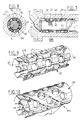
- Figures 3 and 4 show in more detail the mixing section of the rotor 6 from figure 2.
- This mixing section can also be applied in the extruder 1 according to fig. 1, with or without the annular valve body 17 with its valve seat 18.
- the rotor 6 mixing cavities 22 and 23 are arranged peripherally in staggered rows relative to each other.
- the mixing ring 26 is provided with radially directed passages 27 arranged therein in the same pattern.
- the mixing ring 26 undergoes a force in forward direction through the flow of the material for mixing which results in it being pressed against the rotor nose 19. Owing to the presence of the material and the embodiment of the contact surfaces there is little friction hereby so that the rotational speed difference between the rotor 6 and the mixing ring 26 is hardly influenced.
- the mixing ring passages 27 and the rotor mixing cavities 22 and 23 are axially displaced relative to each other in the configuration most favourable for mixing.
- the mixing ring 26 can slide easily onto the rotor part 21 when this part is detachably fastened to the threaded section 7 of rotor 6.
- This mixing ring 26 is very simple to machine manufacture.
- the mixing ring 26 provided with the radially directed passages 27 is located around a narrowed rotor portion 28, the surface 29 of which is smooth, in other words there are no mixing members present in the surface 29 which co-act with the passages 27.
- the mixing ring 38 is provided with radially directed passages 27 which are connected to each other by means of longitudinal grooves 40 arranged in the external surface 39 and longitudinal grooves 42 arranged in the interior surface 41.
- passages 27 connected by longitudinal grooves 41 and 42 a narrowed rotor portion 21 with a smooth exterior surface can also be used in this case.
- figure 10 shows a variant whereby the mixing ring 43 is provided on its exterior surface 39 with helically arranged longitudinal grooves 44 and on its interior surface 41 with helically arranged longitudinal grooves 45.
- the lengthwise grooves 44 and 45 have opposing thread directions. In order to avoid flow-back of material along the lengthwise grooves 44 and 45 during injection moulding the lengthwise grooves 44 and 45 do not communicate with the valve body 17.
- the mixer device according to the invention can be used for mixing viscous materials such as melted plastics and rubber, materials such as soap and clay in addition to foodstuffs such as dough and margarine.
Landscapes
- Engineering & Computer Science (AREA)
- Mechanical Engineering (AREA)
- Manufacturing & Machinery (AREA)
- Processing And Handling Of Plastics And Other Materials For Molding In General (AREA)
- Injection Moulding Of Plastics Or The Like (AREA)
- Extrusion Moulding Of Plastics Or The Like (AREA)
- Mixers Of The Rotary Stirring Type (AREA)
Claims (16)
Priority Applications (1)
| Application Number | Priority Date | Filing Date | Title |
|---|---|---|---|
| AT89201132T ATE78208T1 (de) | 1988-05-03 | 1989-05-02 | Mischvorrichtung mit verteilungsmischwirkung fuer eine schneckenpresse, eine spritzgiessmaschine und dergleichen. |
Applications Claiming Priority (2)
| Application Number | Priority Date | Filing Date | Title |
|---|---|---|---|
| NL8801156 | 1988-05-03 | ||
| NL8801156A NL8801156A (nl) | 1988-05-03 | 1988-05-03 | Menginrichting met distributiemengwerking, voor een extruder, een spuitgietmachine en dergelijke. |
Publications (2)
| Publication Number | Publication Date |
|---|---|
| EP0340873A1 EP0340873A1 (de) | 1989-11-08 |
| EP0340873B1 true EP0340873B1 (de) | 1992-07-15 |
Family
ID=19852245
Family Applications (1)
| Application Number | Title | Priority Date | Filing Date |
|---|---|---|---|
| EP89201132A Expired - Lifetime EP0340873B1 (de) | 1988-05-03 | 1989-05-02 | Mischvorrichtung mit Verteilungsmischwirkung für eine Schneckenpresse, eine Spritzgiessmaschine und dergleichen |
Country Status (8)
| Country | Link |
|---|---|
| US (2) | US5013233A (de) |
| EP (1) | EP0340873B1 (de) |
| JP (1) | JPH0263538A (de) |
| AT (1) | ATE78208T1 (de) |
| CA (1) | CA1311748C (de) |
| DE (1) | DE68902084T2 (de) |
| ES (1) | ES2033518T3 (de) |
| NL (1) | NL8801156A (de) |
Cited By (2)
| Publication number | Priority date | Publication date | Assignee | Title |
|---|---|---|---|---|
| WO2004035282A2 (en) | 2002-10-21 | 2004-04-29 | Basf Aktiengesellschaft | Mixing device |
| US12157261B2 (en) | 2018-11-22 | 2024-12-03 | Buss Ag | Mixing and plasticating machine having a filling device with a separating wall, where the filling device is arranged on a housing of the machine, and method related thereto |
Families Citing this family (49)
| Publication number | Priority date | Publication date | Assignee | Title |
|---|---|---|---|---|
| NL8801156A (nl) * | 1988-05-03 | 1989-12-01 | Univ Twente | Menginrichting met distributiemengwerking, voor een extruder, een spuitgietmachine en dergelijke. |
| GB9013747D0 (en) * | 1990-06-20 | 1990-08-08 | Rapra Techn Ltd | Production of thermoplastics foams |
| CA2089267C (en) * | 1990-08-27 | 2002-01-29 | Philip Strubing Blatz | Direct fabrication |
| US5130076A (en) * | 1990-08-27 | 1992-07-14 | E. I. Du Pont De Nemours And Company | Direct fabrication |
| US5114658A (en) * | 1990-11-15 | 1992-05-19 | E. I. Du Pont De Nemours And Company | One step preparation and fabrication of partially grafted flexible thermoplastic compositions |
| US5112213A (en) * | 1991-02-26 | 1992-05-12 | Van Dorn Company | Driven ring-type non-return valve for injection molding |
| GB2254283B (en) * | 1991-03-26 | 1995-02-15 | Frenkel Ag C D | Improvements in plasticising units for screw injection moulding machines |
| JP3076099B2 (ja) * | 1991-09-03 | 2000-08-14 | 住友重機械プラスチックマシナリー株式会社 | スクリュヘッド構造体 |
| DE4236662C2 (de) * | 1991-11-02 | 1996-10-31 | Frank Truckenmueller | Vorrichtung zur Herstellung von Formteilen aus plastifizierbarem Material und faserförmigen Einlagen |
| AU6772294A (en) * | 1993-04-22 | 1994-11-21 | Ralph Kirtland | Continuous feed, low pressure process and apparatus for manufacturing thermoplastic posts |
| DE4402666A1 (de) * | 1994-01-29 | 1995-08-03 | Roehm Gmbh | Verfahren zum kurzzeitigen Behandeln einer Kunststoffschmelze mit einem flüssigen Behandlungsmittel und dabei hergestellter thermoplastischer Kunststoff |
| US5653534A (en) * | 1994-10-12 | 1997-08-05 | Sumitomo Chemical Company, Limited | Screw apparatus and method for supplying reinforcing fiber-containing molten resin using the apparatus |
| ZA9510847B (en) * | 1994-12-23 | 1997-06-20 | Unilever Plc | Process for the production of liquid compositions |
| US5573331A (en) * | 1995-09-08 | 1996-11-12 | Lin; Ping H. | Multiple-stage screw for blending materials |
| US5916524A (en) * | 1997-07-23 | 1999-06-29 | Bio-Dot, Inc. | Dispensing apparatus having improved dynamic range |
| USRE38281E1 (en) | 1996-07-26 | 2003-10-21 | Biodot, Inc. | Dispensing apparatus having improved dynamic range |
| ID24359A (id) | 1997-05-16 | 2000-07-13 | Unilever Nv | Proses untuk memproduksi suatu komposisi detergen |
| US5837295A (en) * | 1997-10-16 | 1998-11-17 | The Goodyear Tire & Rubber Company | Scraper blades for extruder |
| US6136246A (en) * | 1997-11-07 | 2000-10-24 | Rauwendaal Extrusion Engineering | Screw extruder with improved dispersive mixing elements |
| US6062717A (en) * | 1997-11-18 | 2000-05-16 | Bbs Corporation | Chopper mixing screw |
| DE19756126C2 (de) * | 1997-12-17 | 2002-05-02 | Thueringisches Inst Textil | Verfahren zur Herstellung von langfaserverstärkten Kunststofferzeugnissen durch Plastifizierung von Hybrid-Faserbändern auf Schneckenmaschinen |
| ES2149086B1 (es) * | 1998-02-20 | 2001-05-01 | Pellicer Carlos F | Procedimiento para la obtencion y la utilizacion de una pasta fina moldeable e instalacion para su realizacion. |
| US6203311B1 (en) * | 1998-05-04 | 2001-03-20 | Robert F. Dray | Sliding ring non-return valve |
| US5988866A (en) * | 1998-05-22 | 1999-11-23 | Barr; Robert A. | Floating sleeve mixer and method |
| US6254266B1 (en) * | 1998-05-22 | 2001-07-03 | Robert A. Barr | Floating ring mixer for extruder |
| US6241375B1 (en) * | 1998-08-01 | 2001-06-05 | Peter Wang | Shear ring screw |
| EP1055930A3 (de) | 1999-05-26 | 2003-10-15 | Nihon Densan Read Kabushiki Kaisha, (Nidec-Read Corporation) | Vorrichtung zur Prüfung von Leiterplatten und Sonde zur Verwendung in einem solchen Gerät |
| AU8560001A (en) * | 2000-09-08 | 2002-03-22 | Commw Scient Ind Res Org | Fluid mixer |
| DE10055190A1 (de) * | 2000-11-07 | 2002-05-16 | Basf Ag | Verfahren zur Herstellung folienhinterspritzter Kunststoffformteile sowie folienhinterspritzte Kunststoffformteile |
| WO2003024683A1 (de) * | 2001-09-14 | 2003-03-27 | Bühler AG | Elastomermischungen für die gummiherstellung |
| DE10217758B4 (de) | 2002-04-20 | 2005-06-16 | Krauss-Maffei Kunststofftechnik Gmbh | Rückstromsperre für Spritzgießmaschine |
| US6709147B1 (en) | 2002-12-05 | 2004-03-23 | Rauwendaal Extrusion Engineering, Inc. | Intermeshing element mixer |
| DE10306476B3 (de) * | 2003-02-14 | 2004-08-12 | Schürmann, Erich, Prof. Dr.-Ing. | Spritzaggregat einer Spritzgießmaschine |
| JP2005066946A (ja) * | 2003-08-21 | 2005-03-17 | Ngk Insulators Ltd | 押出機用スクリュー、スクリュー式押出機、及びこれを用いた混練押出装置 |
| US7316501B2 (en) * | 2004-05-20 | 2008-01-08 | Christian Thoma | Apparatus and method for mixing dissimilar fluids |
| KR100516470B1 (ko) * | 2004-07-29 | 2005-09-21 | 삼흥종합환경 (주) | 재생골재용 표면박리기 |
| US7390118B2 (en) * | 2004-10-15 | 2008-06-24 | Husky Injection Molding Systems Ltd. | Extruder assembly |
| EP1754530A1 (de) * | 2005-08-18 | 2007-02-21 | StaMixCo Technology AG | Mischelement zum Invertieren und Mischen von strömenden Stoffen in einem Strömungskanal, Bausatz und Mischer enthaltend dergestalte Mischelemente, sowie Verfahren zum Mischen eines strömenden Stoffes in einem Strömungskanal |
| US20070065538A1 (en) * | 2005-09-16 | 2007-03-22 | Husky Injection Molding Systems Ltd. | Molding system having valve including pump |
| US8313051B2 (en) * | 2008-03-05 | 2012-11-20 | Sealed Air Corporation (Us) | Process and apparatus for mixing a polymer composition and composite polymers resulting therefrom |
| DE102011014467A1 (de) * | 2011-03-19 | 2012-09-20 | Oerlikon Textile Gmbh & Co. Kg | Vorrichtung zum Extrudieren einer Polymerschmelze |
| CN103862700B (zh) * | 2014-03-17 | 2016-06-01 | 大连橡胶塑料机械股份有限公司 | 挤压脱水机模板调节装置 |
| CN104002447B (zh) * | 2014-05-15 | 2015-10-28 | 华南理工大学 | 一种偏心转子体积脉动形变塑化输运方法及装置 |
| DE102016120325A1 (de) * | 2016-10-25 | 2018-04-26 | Kraussmaffei Technologies Gmbh | Mischaufsatz für eine Schnecke |
| CN106808666B (zh) * | 2017-03-20 | 2019-10-18 | 北京化工大学 | 高比扭矩强化传热与混炼塑化挤出机 |
| CN110465223B (zh) * | 2019-09-06 | 2021-09-21 | 韩山师范学院 | 一次性可降解航空餐勺生产装置 |
| CN111791528A (zh) * | 2020-07-24 | 2020-10-20 | 张建华 | 一种有机硅挤出装置 |
| DE102021002064A1 (de) | 2021-04-20 | 2022-10-20 | Bb Engineering Gmbh | Extrudermischer |
| DE102024000885A1 (de) * | 2024-03-19 | 2025-09-25 | Bb Engineering Gmbh | Dynamische Mischvorrichtung für ein Fluid, Extruder mit einer derartigen Mischvorrichtung und Verfahren zum Betreiben einer dynamischen Mischvorrichtung für ein Fluid |
Family Cites Families (16)
| Publication number | Priority date | Publication date | Assignee | Title |
|---|---|---|---|---|
| GB930339A (en) * | 1961-05-01 | 1963-07-03 | Metal Box Co Ltd | Improvements in or relating to the extrusion of molten thermoplastic material |
| CH395528A (de) * | 1962-10-12 | 1965-07-15 | Buss Ag | Verfahren zum Betrieb einer Austragsvorrichtung für eine kontinuierliche Schneckenmaschine |
| FR1523602A (fr) * | 1966-05-06 | 1968-05-03 | Bayer Ag | Procédé de mélange et d'homogénéisation, notamment de liquides visqueux et mélangeurs pour la mise en oeuvre de ce procédé |
| DE1778515B1 (de) * | 1968-05-08 | 1972-02-03 | Basf Ag | Knetelement an der schneckenspitze einer thermoplastischen kunststoffe verarbeitenden schneckenpresse |
| GB1246021A (en) * | 1968-05-16 | 1971-09-15 | Barmag Barmer Maschf | Screw extruder |
| DE2162709C3 (de) * | 1971-12-17 | 1974-12-05 | Vereinigung Zur Foerderung Des Instituts Fuer Kunststoffverarbeitung In Industrie Und Handwerk An Der Rhein.-Westf. Techn.Hochschule Aachen E.V., 5100 Aachen | Mischvorrichtung für eine drehbare und axial verschiebbare Plastifizierschnecke |
| DE2327540A1 (de) * | 1973-05-30 | 1974-12-19 | Basf Ag | Mischelement an der schneckenspitze einer thermoplastische kunststoffe verarbeitenden schneckenpresse |
| DD124023A1 (de) * | 1974-10-09 | 1977-02-02 | ||
| JPS5214659A (en) * | 1975-07-25 | 1977-02-03 | Mitsubishi Heavy Ind Ltd | Injection molding machine |
| FR2319478A1 (fr) * | 1975-07-30 | 1977-02-25 | Gen Electric | Extrudeuse et procede d'extrusion de materiaux thermoplastiques |
| DE2635144A1 (de) * | 1976-08-05 | 1978-02-09 | Demag Kunststofftech | Rueckstroemsperre an schneckenspritzgiessmaschinen |
| US4419014A (en) * | 1980-09-23 | 1983-12-06 | Rubber And Plastics Research Association Of Great Britain | Extruder mixer |
| SU925653A1 (ru) * | 1980-10-08 | 1982-05-07 | Днепропетровский химико-технологический институт им.Ф.Э.Дзержинского | Черв чный экструдер дл полимерных материалов |
| SU925654A1 (ru) * | 1980-10-17 | 1982-05-07 | Всесоюзный Научно-Исследовательский Институт Машин Для Производства Синтетических Волокон | Экструдер-смеситель |
| US4595546A (en) * | 1983-11-14 | 1986-06-17 | Crompton & Knowles Corporation | Manufacture of elongated extruded cross-linked products |
| NL8801156A (nl) * | 1988-05-03 | 1989-12-01 | Univ Twente | Menginrichting met distributiemengwerking, voor een extruder, een spuitgietmachine en dergelijke. |
-
1988
- 1988-05-03 NL NL8801156A patent/NL8801156A/nl not_active Application Discontinuation
-
1989
- 1989-05-01 US US07/346,051 patent/US5013233A/en not_active Expired - Fee Related
- 1989-05-02 CA CA000598481A patent/CA1311748C/en not_active Expired - Lifetime
- 1989-05-02 EP EP89201132A patent/EP0340873B1/de not_active Expired - Lifetime
- 1989-05-02 ES ES198989201132T patent/ES2033518T3/es not_active Expired - Lifetime
- 1989-05-02 DE DE8989201132T patent/DE68902084T2/de not_active Expired - Fee Related
- 1989-05-02 JP JP1113535A patent/JPH0263538A/ja not_active Withdrawn
- 1989-05-02 AT AT89201132T patent/ATE78208T1/de not_active IP Right Cessation
-
1991
- 1991-01-09 US US07/619,225 patent/US5158784A/en not_active Expired - Lifetime
Cited By (2)
| Publication number | Priority date | Publication date | Assignee | Title |
|---|---|---|---|---|
| WO2004035282A2 (en) | 2002-10-21 | 2004-04-29 | Basf Aktiengesellschaft | Mixing device |
| US12157261B2 (en) | 2018-11-22 | 2024-12-03 | Buss Ag | Mixing and plasticating machine having a filling device with a separating wall, where the filling device is arranged on a housing of the machine, and method related thereto |
Also Published As
| Publication number | Publication date |
|---|---|
| US5013233A (en) | 1991-05-07 |
| DE68902084D1 (de) | 1992-08-20 |
| DE68902084T2 (de) | 1993-01-14 |
| US5158784A (en) | 1992-10-27 |
| JPH0263538A (ja) | 1990-03-02 |
| ATE78208T1 (de) | 1992-08-15 |
| ES2033518T3 (es) | 1993-03-16 |
| CA1311748C (en) | 1992-12-22 |
| NL8801156A (nl) | 1989-12-01 |
| EP0340873A1 (de) | 1989-11-08 |
Similar Documents
| Publication | Publication Date | Title |
|---|---|---|
| EP0340873B1 (de) | Mischvorrichtung mit Verteilungsmischwirkung für eine Schneckenpresse, eine Spritzgiessmaschine und dergleichen | |
| US4408887A (en) | Continuous kneader | |
| US4779989A (en) | Transfer mixer assembly for use with an extruder screw of a polymer extruder or the like | |
| US4025058A (en) | Continuous extruder for thermosetting resins | |
| KR900001957B1 (ko) | 공동이송 혼합압출기 | |
| US3866890A (en) | Apparatus for simultaneous plasticating and mixing | |
| DE4236662A1 (en) | Extruder for use with long fibre FRP - feeds fibres continuously into barrel and has special recesses on screw and barrel wall to mix in long fibres without shortening them | |
| DE2943230C2 (de) | Knetvorrichtung für Kunststoffmischungen | |
| DE2943820C2 (de) | Extruderanlage | |
| DE4301431A1 (en) | Two=stage serial extruder - comprises preliminary extruder and second stage extruder with screw having rows of ribs at front end the parameters of which can be changed at each step | |
| JP2020536734A (ja) | 混合混練機用の非対称3ブレードスクリュー型シャフト | |
| US3936038A (en) | Mixer for plastic injection molding machine | |
| US4007922A (en) | Extruding device for high molecular materials | |
| US5178458A (en) | Extruder screw mixing head | |
| DE2415896B2 (de) | Schneckenstrangpresse | |
| US3387826A (en) | Mixer apparatus | |
| US5348388A (en) | Extrusion apparatus for mixing and extruding thermo-plastic materials | |
| US3942773A (en) | Method and apparatus for extruding melted plastic mixtures | |
| US3869111A (en) | Apparatus for mixing rubber, elastomer, plastic and the like | |
| US4022440A (en) | Method for producing plastic compound and an apparatus therefor | |
| DE2637134A1 (de) | Plastifiziervorrichtung einer kunststoff-spritzgiessmaschine | |
| US4052038A (en) | Screw extruder for thermoplastics synthetic materials or elastomers | |
| US4196163A (en) | Production of stripped soap strands and apparatus for its production | |
| AU595313B2 (en) | Extruder | |
| KR20000047752A (ko) | 자체의 플랜지들 중 적어도 하나의 확대에 따라 가변하는혼합물내로의 진입각을 가진 탄성중합체 등을 혼합하는기계용 로터 |
Legal Events
| Date | Code | Title | Description |
|---|---|---|---|
| PUAI | Public reference made under article 153(3) epc to a published international application that has entered the european phase |
Free format text: ORIGINAL CODE: 0009012 |
|
| AK | Designated contracting states |
Kind code of ref document: A1 Designated state(s): AT CH DE ES FR GB IT LI NL |
|
| 17P | Request for examination filed |
Effective date: 19900508 |
|
| 17Q | First examination report despatched |
Effective date: 19910301 |
|
| GRAA | (expected) grant |
Free format text: ORIGINAL CODE: 0009210 |
|
| AK | Designated contracting states |
Kind code of ref document: B1 Designated state(s): AT CH DE ES FR GB IT LI NL |
|
| REF | Corresponds to: |
Ref document number: 78208 Country of ref document: AT Date of ref document: 19920815 Kind code of ref document: T |
|
| REF | Corresponds to: |
Ref document number: 68902084 Country of ref document: DE Date of ref document: 19920820 |
|
| ET | Fr: translation filed | ||
| ITF | It: translation for a ep patent filed | ||
| REG | Reference to a national code |
Ref country code: ES Ref legal event code: FG2A Ref document number: 2033518 Country of ref document: ES Kind code of ref document: T3 |
|
| PLBE | No opposition filed within time limit |
Free format text: ORIGINAL CODE: 0009261 |
|
| STAA | Information on the status of an ep patent application or granted ep patent |
Free format text: STATUS: NO OPPOSITION FILED WITHIN TIME LIMIT |
|
| 26N | No opposition filed | ||
| REG | Reference to a national code |
Ref country code: GB Ref legal event code: IF02 |
|
| PGFP | Annual fee paid to national office [announced via postgrant information from national office to epo] |
Ref country code: ES Payment date: 20050630 Year of fee payment: 17 |
|
| PG25 | Lapsed in a contracting state [announced via postgrant information from national office to epo] |
Ref country code: ES Free format text: LAPSE BECAUSE OF NON-PAYMENT OF DUE FEES Effective date: 20060503 |
|
| PGFP | Annual fee paid to national office [announced via postgrant information from national office to epo] |
Ref country code: GB Payment date: 20060530 Year of fee payment: 18 |
|
| PGFP | Annual fee paid to national office [announced via postgrant information from national office to epo] |
Ref country code: NL Payment date: 20060531 Year of fee payment: 18 Ref country code: IT Payment date: 20060531 Year of fee payment: 18 Ref country code: FR Payment date: 20060531 Year of fee payment: 18 Ref country code: CH Payment date: 20060531 Year of fee payment: 18 |
|
| PGFP | Annual fee paid to national office [announced via postgrant information from national office to epo] |
Ref country code: AT Payment date: 20070525 Year of fee payment: 19 |
|
| PGFP | Annual fee paid to national office [announced via postgrant information from national office to epo] |
Ref country code: DE Payment date: 20070530 Year of fee payment: 19 |
|
| REG | Reference to a national code |
Ref country code: ES Ref legal event code: FD2A Effective date: 20060503 |
|
| REG | Reference to a national code |
Ref country code: CH Ref legal event code: PL |
|
| GBPC | Gb: european patent ceased through non-payment of renewal fee |
Effective date: 20070502 |
|
| PG25 | Lapsed in a contracting state [announced via postgrant information from national office to epo] |
Ref country code: NL Free format text: LAPSE BECAUSE OF NON-PAYMENT OF DUE FEES Effective date: 20071201 |
|
| NLV4 | Nl: lapsed or anulled due to non-payment of the annual fee |
Effective date: 20071201 |
|
| PG25 | Lapsed in a contracting state [announced via postgrant information from national office to epo] |
Ref country code: LI Free format text: LAPSE BECAUSE OF NON-PAYMENT OF DUE FEES Effective date: 20070531 Ref country code: CH Free format text: LAPSE BECAUSE OF NON-PAYMENT OF DUE FEES Effective date: 20070531 |
|
| REG | Reference to a national code |
Ref country code: FR Ref legal event code: ST Effective date: 20080131 |
|
| PG25 | Lapsed in a contracting state [announced via postgrant information from national office to epo] |
Ref country code: GB Free format text: LAPSE BECAUSE OF NON-PAYMENT OF DUE FEES Effective date: 20070502 |
|
| PG25 | Lapsed in a contracting state [announced via postgrant information from national office to epo] |
Ref country code: FR Free format text: LAPSE BECAUSE OF NON-PAYMENT OF DUE FEES Effective date: 20070531 |
|
| PG25 | Lapsed in a contracting state [announced via postgrant information from national office to epo] |
Ref country code: AT Free format text: LAPSE BECAUSE OF NON-PAYMENT OF DUE FEES Effective date: 20080502 |
|
| PG25 | Lapsed in a contracting state [announced via postgrant information from national office to epo] |
Ref country code: DE Free format text: LAPSE BECAUSE OF NON-PAYMENT OF DUE FEES Effective date: 20081202 |
|
| PG25 | Lapsed in a contracting state [announced via postgrant information from national office to epo] |
Ref country code: IT Free format text: LAPSE BECAUSE OF NON-PAYMENT OF DUE FEES Effective date: 20070502 |