EP0340611A2 - Device for combustion air supply controlling - Google Patents
Device for combustion air supply controlling Download PDFInfo
- Publication number
- EP0340611A2 EP0340611A2 EP89107516A EP89107516A EP0340611A2 EP 0340611 A2 EP0340611 A2 EP 0340611A2 EP 89107516 A EP89107516 A EP 89107516A EP 89107516 A EP89107516 A EP 89107516A EP 0340611 A2 EP0340611 A2 EP 0340611A2
- Authority
- EP
- European Patent Office
- Prior art keywords
- combustion air
- control device
- fuel gas
- line
- throughput
- Prior art date
- Legal status (The legal status is an assumption and is not a legal conclusion. Google has not performed a legal analysis and makes no representation as to the accuracy of the status listed.)
- Granted
Links
Images
Classifications
-
- F—MECHANICAL ENGINEERING; LIGHTING; HEATING; WEAPONS; BLASTING
- F23—COMBUSTION APPARATUS; COMBUSTION PROCESSES
- F23N—REGULATING OR CONTROLLING COMBUSTION
- F23N1/00—Regulating fuel supply
- F23N1/08—Regulating fuel supply conjointly with another medium, e.g. boiler water
- F23N1/085—Regulating fuel supply conjointly with another medium, e.g. boiler water using electrical or electromechanical means
-
- F—MECHANICAL ENGINEERING; LIGHTING; HEATING; WEAPONS; BLASTING
- F23—COMBUSTION APPARATUS; COMBUSTION PROCESSES
- F23N—REGULATING OR CONTROLLING COMBUSTION
- F23N2225/00—Measuring
- F23N2225/04—Measuring pressure
- F23N2225/06—Measuring pressure for determining flow
-
- F—MECHANICAL ENGINEERING; LIGHTING; HEATING; WEAPONS; BLASTING
- F23—COMBUSTION APPARATUS; COMBUSTION PROCESSES
- F23N—REGULATING OR CONTROLLING COMBUSTION
- F23N2233/00—Ventilators
- F23N2233/06—Ventilators at the air intake
- F23N2233/08—Ventilators at the air intake with variable speed
-
- F—MECHANICAL ENGINEERING; LIGHTING; HEATING; WEAPONS; BLASTING
- F23—COMBUSTION APPARATUS; COMBUSTION PROCESSES
- F23N—REGULATING OR CONTROLLING COMBUSTION
- F23N2235/00—Valves, nozzles or pumps
- F23N2235/12—Fuel valves
- F23N2235/16—Fuel valves variable flow or proportional valves
-
- F—MECHANICAL ENGINEERING; LIGHTING; HEATING; WEAPONS; BLASTING
- F23—COMBUSTION APPARATUS; COMBUSTION PROCESSES
- F23N—REGULATING OR CONTROLLING COMBUSTION
- F23N2239/00—Fuels
- F23N2239/04—Gaseous fuels
-
- F—MECHANICAL ENGINEERING; LIGHTING; HEATING; WEAPONS; BLASTING
- F23—COMBUSTION APPARATUS; COMBUSTION PROCESSES
- F23N—REGULATING OR CONTROLLING COMBUSTION
- F23N2241/00—Applications
- F23N2241/04—Heating water
Definitions
- the invention relates first of all to a method for regulating the supply of combustion air and / or fuel gas to a combustion of a fuel gas / combustion air mixture which serves to heat a flowing, fluid medium, in particular water.
- the object of the invention is to provide a particularly sensitive control which ensures permanent compliance with an optimal composition of the mixture and thus an optimal and accordingly pollutant-free combustion.
- the combustion air and / or the fuel gas throughput is regulated as a function of the respective throughput of the medium to be heated.
- a device suitable for carrying out this method comprises, within the scope of the invention, a heat exchanger fed via a water supply line, and a gas burner assigned to this heat exchanger, to which combustion gas is supplied via a nozzle and via a combustion air guide by means of a blower, combustion air.
- a device is characterized according to the invention by a water flow meter arranged in the water supply or dispensing line and a control device controlled by it for regulating the combustion air and fuel gas throughput.
- control device for regulating the combustion air is set designed as a speed controller of the blower motor.
- control device can be connected via a control line to a valve which continuously adjusts the fuel gas supply to the gas burner and is arranged in the fuel gas supply line to the gas burner.
- a piezoelectric pressure sensor, a potentiometer or an optical sensor can be provided as the signal transmitter;
- a sensor can consist, for example, of an aperture movable between a light source and a light receiver, the aperture being adjustable by the water flow meter and the light receiver embodying the signal transmitter.
- control device for controlling the combustion air throughput can consist of a control loop with feedback, wherein a pole wheel is arranged on the fan shaft to generate the feedback signal, which in turn acts on a Hall sensor.
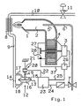
- FIG. 1 shows a gas burner 1 with a combustion air guide 2, in which a blower serving to supply the combustion air is arranged with a blower wheel 4 driven by a blower motor 3.
- the fuel gas is supplied to the gas burner 1 via a nozzle 5 from a fuel gas supply line 6 in a quantity regulated by means of the control valve 7.
- this gas burner 1 there is a heat exchanger 8, which is supplied with water from a water supply line 9 and to which a tap line 10 with a tap valve 11 for the heated water is connected.
- the water throughput in the water supply line 9 and the tap line 10, that is to say the amount of water flowing through these lines per unit of time, is measured by a differential pressure transmitter 12 with a membrane 13 and a flow restrictor 14.
- the membrane chambers 15 and 16 are connected via the branch lines 17 and 18 upstream and downstream of the throttle 14 to the water supply line 9 and the water throughput can be determined with the differential pressure, the measured value of which - in the embodiment according to FIG. 1 - via a displacement sensor 19 of the membrane 13 a signal transmitter designed as a pressure sensor 21, generally designated 20, is transmitted.
- This signal generator 20 is connected via a control line 22 to an electronic control device 23, which in turn is connected via the control line 24 to the valve 7 regulating the fuel gas throughput in the fuel gas supply line 6 and on the other hand via a control line 25 to a speed controller 26 of the blower motor 3.
- the control of the speed of the blower motor 3 and the fuel gas control valve 7 takes place such that the combustion air throughput and the fuel gas throughput are not only optimally coordinated with one another, but also correspond to the burner output required in each case.
- the feedback of the speed controller 26 is generated via the control line 37 by the Hall sensor 28 assigned to a pole wheel 27 of the fan output shaft.
- the membrane 13 is assigned a potentiometer, on the wire turns 30 of which an assigned actuator 29 of the membrane 13 acts as a sliding contact and determines the size of a signal current transmitted via the control line 22 of the control device 23.
- the signal generator 20 includes an orifice 31 which is adjustable by an actuator 29 of the membrane 13 and which is located between a light source 35 supplied via a circuit 32 with a current source 33 and a resistor 34 and a light-sensitive resistor 36 which acts as a signal generator the control line 22 to the control device 23 is active.
Abstract
Description
Die Erfindung betrifft zunächst ein Verfahren zur Regelung der Verbrennungsluft- und/oder Brenngas-Zufuhr zu einer der Beheizung eines strömenden, fluiden Mediums, insbesondere Wasser, dienenden Verbrennung eines Brenngas-Verbrennungsluft-Gemisches.The invention relates first of all to a method for regulating the supply of combustion air and / or fuel gas to a combustion of a fuel gas / combustion air mixture which serves to heat a flowing, fluid medium, in particular water.
Aufgabe der Erfindung ist es, eine besonders feinfühlige Regelung zu schaffen, die eine dauernde Einhaltung einer optimalen Zusammensetzung des Gemisches und damit eine optimale und dementsprechend schadstofffreie Verbrennung gewährleistet.The object of the invention is to provide a particularly sensitive control which ensures permanent compliance with an optimal composition of the mixture and thus an optimal and accordingly pollutant-free combustion.
Erfindungsgemäß wird der Verbrennungsluft- und/oder der Brenngas- Durchsatz in Abhängigkeit vom jeweiligen Durchsatz des zu beheizenden Mediums geregelt.According to the invention, the combustion air and / or the fuel gas throughput is regulated as a function of the respective throughput of the medium to be heated.
Eine zur Durchführung dieses Verfahrens geeignete Vorrichtung umfaßt im Rahmen der Erfindung einen über eine Wasserzufuhrleitung gespeisten Wärmetauscher, sowie einen diesem Wärmetauscher zugeordneten Gasbrenner, dem über eine Düse Brenngas und über eine Verbrennungsluftführung mittels eines Gebläses Verbrennungsluft zugeführt wird. Eine solche Vorrichtung ist erfindungsgemäß gekennzeichnet durch einen in der Wasserzufuhr- oder Zapfleitung angeordneten Wasserdurchsatzmesser und eine von ihm gesteuerte Regelvorrichtung zur Regelung des Verbrennungsluft- und Brenngasdurchsatzes.A device suitable for carrying out this method comprises, within the scope of the invention, a heat exchanger fed via a water supply line, and a gas burner assigned to this heat exchanger, to which combustion gas is supplied via a nozzle and via a combustion air guide by means of a blower, combustion air. Such a device is characterized according to the invention by a water flow meter arranged in the water supply or dispensing line and a control device controlled by it for regulating the combustion air and fuel gas throughput.
Nach einer bevorzugten, gut praktikablen Ausführungsform ist die Regelvorrichtung zur Regelung des Verbrennungsluftdurch satzes als Drehzahlregler des Gebläsemotors ausgebildet.According to a preferred, well practicable embodiment, the control device for regulating the combustion air is set designed as a speed controller of the blower motor.
Vorteilhafterweise kann dieselbe Regelvorrichtung über eine Steuerleitung mit einem die Brenngaszufuhr zum Gasbrenner stufenlos regelnden, in der Brenngaszufuhrleitung zum Gasbrenner angeordneten Ventil verbunden sein.Advantageously, the same control device can be connected via a control line to a valve which continuously adjusts the fuel gas supply to the gas burner and is arranged in the fuel gas supply line to the gas burner.
Hinsichtlich der Ausbildung eines dem Wasserdurchsatzmesser als Signalgeber für die Regelvorrichtung zuzuordnenden und über eine Steuerleitung mit der Regelvorrichtung zu verbindenden Signalgebers bestehen im Rahmen der Erfindung verschiedenerlei zielführende und wahlweise zu verwirklichende Möglichkeiten.With regard to the design of a signal transmitter to be assigned to the water flow meter as a signal transmitter for the control device and to be connected to the control device via a control line, there are various target-oriented and optionally implementable possibilities within the scope of the invention.
So kann als Signalgeber ein piezoelektrischer Drucksensor, ein Potentiometer oder ein optischer Fühler vorgesehen werden; im letztgenannten Fall kann ein solcher Fühler beispielsweise aus einer zwischen einer Lichtquelle und einem Lichtempfänger beweglichen Blende bestehen, wobei die Blende vom Wasserdurchsatzmesser verstellbar ist und der Lichtempfänger den Signalgeber verkörpert.For example, a piezoelectric pressure sensor, a potentiometer or an optical sensor can be provided as the signal transmitter; In the latter case, such a sensor can consist, for example, of an aperture movable between a light source and a light receiver, the aperture being adjustable by the water flow meter and the light receiver embodying the signal transmitter.
Schließlich kann die Regelvorrichtung zur Regelung des Verbrennungsluftdurchsatzes aus einem Regelkreis mit Rückführung bestehen, wobei zur Erzeugung des Rückführungssignales ein Polrad auf der Gebläsewelle angeordnet ist, das wiederum auf einen Hallsensor einwirkt.Finally, the control device for controlling the combustion air throughput can consist of a control loop with feedback, wherein a pole wheel is arranged on the fan shaft to generate the feedback signal, which in turn acts on a Hall sensor.
Ausführungsbeispiele erfindungsgemäßer Vorrichtungen sind nachstehend an Hand von Zeichnungen erläutert.Embodiments of devices according to the invention are explained below with reference to drawings.
In diesen Zeichnungen zeigt
- Fig.1 die gesamte Vorrichtung in schematischer Darstellunbg und die
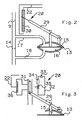
- Fig. 2 und 3 stellen in Ausschnitten aus diesem Schema Varianten des Signalgebers des Wasserdurchsatzmessers dar.
- 1 shows the entire device in a schematic representation and the
- 2 and 3 show in sections from this scheme variants of the signal transmitter of the water flow meter.
Zunächst zeigt Fig.1 einen Gasbrenner 1 mit einer Verbrennungsluftführung 2, in der ein der Verbrennungsluftzufuhr dienendes Gebläse mit einem über einen Gebläsemotor 3 angetriebenen Gebläserad 4 angeordnet ist. Das Brenngas wird dem Gasbrenner 1 über eine Düse 5 aus einer Brenngaszufuhrleitung 6 in einer mittels des Regelventiles 7 geregelten Menge zugeführt.1 shows a
In der Abgasführung dieses Gasbrenners 1 befindet sich ein Wärmetauscher 8, der aus einer Wasserzufuhrleitung 9 mit Wasser versorgt wird und dem eine Zapfleitung 10 mit einem Zapfventil 11 für das beheizte Wasser angeschlossen ist.In the exhaust gas duct of this
Der Wasserdurchsatz in der Wasserzufuhrleitung 9 und der Zapfleitung 10, also die diese Leitungen pro Zeiteinheit durchströmende Wassermenge, wird von einem Differenzdruckgeber 12 mit einer Membran 13 und einer Strömungsdrossel 14 gemessen. Die Membrankammern 15 und 16 sind über die Zweigleitungen 17 und 18 vor und hinter der Drossel 14 mit der Wasserzufuhrleitung 9 verbunden und mit dem Differenzdruck ist der Wasserdurchsatz bestimmbar, dessen Meßwert - bei dem Ausführungsbeispiel nach Fig. 1 - über einen Weggeber 19 der Membran 13 einem als Drucksensor 21 ausgebildeten, allgemein mit 20 bezeichneten Signalgeber übermittelt wird. Dieser Signalgeber 20 ist über eine Steuerleitung 22 mit einer elektronischen Regelvorrichtung 23 verbunden, die ihrerseits über die Steuerleitung 24 mit dem den Brenngasdurchsatz in der Brenngaszufuhrleitung 6 regelnden Ventil 7 und anderseits über eine Steuerleitung 25 mit einem Drehzahlregler 26 des Gebläsemotors 3 verbunden ist.The water throughput in the
In Abhängigkeit vom jeweiligen variablen Wasserdurchsatz in der Wasserzufuhrleitung 9 erfolgt die Steuerung der Drehzahl des Gebläsemotors 3 sowie des Brenngasregelventiles 7 derart, daß der Verbrennungsluftdurchsatz und der Brenngasdurchsatz nicht nur optimal aufeinander abgestimmt sind, sondern auch der jeweils erforderlichen Brennerleistung entsprechen.Depending on the respective variable water throughput in the
Die Rückführung des Drehzahlreglers 26 wird über die Steuerleitung 37 von dem einem Polrad 27 der Gebläseabtriebswelle zugeordneten Hall-Sensor 28 erzeugt.The feedback of the
Bei der Ausführungsform des Signalgebers 20 nach Fig.2 ist der Membran 13 ein Potentiometer zugeordnet, auf dessen Drahtwindungen 30 ein zugeordnetes Stellglied 29 der Membran 13 als Schleifkontakt einwirkt und die Größe eines über die Steuerleitung 22 der Regelvorrichtung 23 übermittelten Signalstromes festlegt.In the embodiment of the
Nach Fig.3 gehört zum Signalgeber 20 eine von einem Stellglied 29 der Membran 13 verstellbare Blende 31, die sich zwischen einer über einen Stromkreis 32 mit einer Stromquelle 33 und einem Widerstand 34 versorgten Lichtquelle 35 und einem lichtempfindlichen Widerstand 36 befindet, der als Signalgeber über die Steuerleitung 22 zur Regelvorrichtung 23 tätig ist.According to FIG. 3, the
Claims (8)
Priority Applications (1)
| Application Number | Priority Date | Filing Date | Title |
|---|---|---|---|
| AT89107516T ATE85694T1 (en) | 1988-05-03 | 1989-04-26 | DEVICE FOR ADJUSTING THE COMBUSTION AIR SUPPLY. |
Applications Claiming Priority (2)
| Application Number | Priority Date | Filing Date | Title |
|---|---|---|---|
| DE3814992 | 1988-05-03 | ||
| DE3814992 | 1988-05-03 |
Publications (3)
| Publication Number | Publication Date |
|---|---|
| EP0340611A2 true EP0340611A2 (en) | 1989-11-08 |
| EP0340611A3 EP0340611A3 (en) | 1990-12-05 |
| EP0340611B1 EP0340611B1 (en) | 1993-02-10 |
Family
ID=6353486
Family Applications (1)
| Application Number | Title | Priority Date | Filing Date |
|---|---|---|---|
| EP89107516A Expired - Lifetime EP0340611B1 (en) | 1988-05-03 | 1989-04-26 | Device for combustion air supply controlling |
Country Status (4)
| Country | Link |
|---|---|
| EP (1) | EP0340611B1 (en) |
| AT (1) | ATE85694T1 (en) |
| DE (1) | DE58903487D1 (en) |
| ES (1) | ES2039738T3 (en) |
Cited By (2)
| Publication number | Priority date | Publication date | Assignee | Title |
|---|---|---|---|---|
| GB2400164A (en) * | 2003-04-04 | 2004-10-06 | Carver Plc | Fluid flow control |
| US10247446B2 (en) | 2007-03-09 | 2019-04-02 | Lochinvar, Llc | Control system for modulating water heater |
Families Citing this family (1)
| Publication number | Priority date | Publication date | Assignee | Title |
|---|---|---|---|---|
| WO2006034529A1 (en) * | 2004-09-30 | 2006-04-06 | Rheem Australia Pty Limited | Improvements to water heater control systems, burner control systems and diffusers for gas burners |
Citations (6)
| Publication number | Priority date | Publication date | Assignee | Title |
|---|---|---|---|---|
| GB979181A (en) * | 1961-10-11 | 1965-01-01 | English Electric Co Ltd | Improvements in or relating to liquid flowmeters |
| US3181359A (en) * | 1961-05-18 | 1965-05-04 | Gpe Controls Inc | Flow rate transmitter |
| DE2122114A1 (en) * | 1971-05-05 | 1972-11-16 | Schmitz, Hugo, 4720 Beckum | Flow meter |
| FR2296146A1 (en) * | 1974-12-24 | 1976-07-23 | Saunier Duval | FORCE DRAFT GAS BOILER REGULATION DEVICE |
| JPS59129324A (en) * | 1983-01-14 | 1984-07-25 | Omron Tateisi Electronics Co | Control device for combustion |
| JPS59221518A (en) * | 1983-05-31 | 1984-12-13 | Hanshin Electric Co Ltd | Gas combustion control system |
-
1989
- 1989-04-26 DE DE8989107516T patent/DE58903487D1/en not_active Expired - Fee Related
- 1989-04-26 AT AT89107516T patent/ATE85694T1/en not_active IP Right Cessation
- 1989-04-26 EP EP89107516A patent/EP0340611B1/en not_active Expired - Lifetime
- 1989-04-26 ES ES198989107516T patent/ES2039738T3/en not_active Expired - Lifetime
Patent Citations (6)
| Publication number | Priority date | Publication date | Assignee | Title |
|---|---|---|---|---|
| US3181359A (en) * | 1961-05-18 | 1965-05-04 | Gpe Controls Inc | Flow rate transmitter |
| GB979181A (en) * | 1961-10-11 | 1965-01-01 | English Electric Co Ltd | Improvements in or relating to liquid flowmeters |
| DE2122114A1 (en) * | 1971-05-05 | 1972-11-16 | Schmitz, Hugo, 4720 Beckum | Flow meter |
| FR2296146A1 (en) * | 1974-12-24 | 1976-07-23 | Saunier Duval | FORCE DRAFT GAS BOILER REGULATION DEVICE |
| JPS59129324A (en) * | 1983-01-14 | 1984-07-25 | Omron Tateisi Electronics Co | Control device for combustion |
| JPS59221518A (en) * | 1983-05-31 | 1984-12-13 | Hanshin Electric Co Ltd | Gas combustion control system |
Non-Patent Citations (2)
| Title |
|---|
| PATENT ABSTRACTS OF JAPAN, Band 8, Nr. 258 (M-340)[1695], 27. November 1984; & JP-A-59 129 324 (TATEISHI DENKI K.K.) 25-07-1984 * |
| PATENT ABSTRACTS OF JAPAN, Band 9, Nr. 98 (M-375)[1871], 27. April 1985; & JP-A-59 221 518 (HANSHIN ELECTRIC K.K.) 13-12-1984 * |
Cited By (4)
| Publication number | Priority date | Publication date | Assignee | Title |
|---|---|---|---|---|
| GB2400164A (en) * | 2003-04-04 | 2004-10-06 | Carver Plc | Fluid flow control |
| GB2400164B (en) * | 2003-04-04 | 2006-04-19 | Carver Plc | Improvements in or relating to fluid control |
| US10247446B2 (en) | 2007-03-09 | 2019-04-02 | Lochinvar, Llc | Control system for modulating water heater |
| US10955169B2 (en) | 2007-03-09 | 2021-03-23 | Lochinvar, Llc | Control system for modulating water heater |
Also Published As
| Publication number | Publication date |
|---|---|
| EP0340611A3 (en) | 1990-12-05 |
| ES2039738T3 (en) | 1993-10-01 |
| EP0340611B1 (en) | 1993-02-10 |
| ATE85694T1 (en) | 1993-02-15 |
| DE58903487D1 (en) | 1993-03-25 |
Similar Documents
| Publication | Publication Date | Title |
|---|---|---|
| EP0818655B1 (en) | Method and device for controlling the size of the flame of a gas cooking apparatus | |
| EP1179159B1 (en) | Regulating device for gas burners | |
| EP0644377A1 (en) | Control device for gas burners | |
| EP0022493A2 (en) | Process and apparatus for the combustionless measurement and/or regulation of the heat quantity supply to gas consumption plants | |
| DE3010014A1 (en) | DEVICE FOR ADJUSTING THE COMBUSTION AIR FLOW FOR COMBUSTION GAS CONSUMERS | |
| DE3638410C2 (en) | ||
| EP0450173A1 (en) | Mixture control device for a pre-mixed gas burner | |
| DE3232421C2 (en) | Circuit arrangement for a heat demand-dependent control of the heating output of heating devices | |
| EP0864067B1 (en) | Gas flame treatment apparatus for pretreatment of surfaces of plastique material by increasing the surface energy at the surfaces to be coated | |
| EP0340611B1 (en) | Device for combustion air supply controlling | |
| DE3913715A1 (en) | Method for regulating the combustion-air and/or burnable-gas supply to a combustion of a burnable-gas/combustion-air mixture and apparatus for carrying out this method | |
| DE2708858C2 (en) | Control device for a burner for flowable fuels | |
| DE3634449C2 (en) | Device for controlling or regulating a mass flow of a gaseous or vaporous or liquid medium | |
| DE2728807A1 (en) | METHOD AND DEVICE FOR CONTROLLING THE AIR FLOW RATE OF A GAS-HEATED, SEALED HOT WATER BOILER | |
| DE2209779B2 (en) | Hot gas piston engine in which the fuel supply to the burner device is regulated by means of a control device that reacts to at least one parameter of the engine | |
| EP0082107A2 (en) | Air mass flow meter for an internal-combustion engine | |
| EP1002998A2 (en) | Heater | |
| EP0036613B1 (en) | Regulation apparatus for a gas-fired water or air heater which is controllable by a temperature sensor | |
| EP0863367B1 (en) | Control device for a gas burner | |
| DE102019114919A1 (en) | Method for regulating a fuel gas operated heater | |
| DE3703934A1 (en) | Device for controlling the fuel and/or air supply to the burner of a heat source | |
| DE688259C (en) | Control device | |
| DE19943612B4 (en) | Method for operating a gas burner with modulating burner output | |
| EP0893414B1 (en) | Method and apparatus for determining and regulating the oxygen contents in the atmosphere above the glass in a feeder channel | |
| DE3009591A1 (en) | Gas burner air-fuel ratio control equipment - is for flue gas preheated air and has flow metering orifice in cold air branch to own recuperator and blast gate |
Legal Events
| Date | Code | Title | Description |
|---|---|---|---|
| PUAI | Public reference made under article 153(3) epc to a published international application that has entered the european phase |
Free format text: ORIGINAL CODE: 0009012 |
|
| AK | Designated contracting states |
Kind code of ref document: A2 Designated state(s): AT BE CH DE ES FR GB GR IT LI LU NL SE |
|
| PUAL | Search report despatched |
Free format text: ORIGINAL CODE: 0009013 |
|
| AK | Designated contracting states |
Kind code of ref document: A3 Designated state(s): AT BE CH DE ES FR GB GR IT LI LU NL SE |
|
| 17P | Request for examination filed |
Effective date: 19901215 |
|
| 17Q | First examination report despatched |
Effective date: 19910214 |
|
| RAP1 | Party data changed (applicant data changed or rights of an application transferred) |
Owner name: VAILLANT GMBH Owner name: VAILLANT-SCHONEWELLE B.V. Owner name: VAILLANT LTD. Owner name: VAILLANT GES.M.B.H Owner name: VAILLANT S.A.R.L Owner name: N.V. VAILLANT S.A. Owner name: JOH. VAILLANT GMBH U. CO. |
|
| GRAA | (expected) grant |
Free format text: ORIGINAL CODE: 0009210 |
|
| AK | Designated contracting states |
Kind code of ref document: B1 Designated state(s): AT BE CH DE ES FR GB GR IT LI LU NL SE |
|
| PG25 | Lapsed in a contracting state [announced via postgrant information from national office to epo] |
Ref country code: GR Free format text: LAPSE BECAUSE OF FAILURE TO SUBMIT A TRANSLATION OF THE DESCRIPTION OR TO PAY THE FEE WITHIN THE PRESCRIBED TIME-LIMIT Effective date: 19930210 |
|
| REF | Corresponds to: |
Ref document number: 85694 Country of ref document: AT Date of ref document: 19930215 Kind code of ref document: T |
|
| PGFP | Annual fee paid to national office [announced via postgrant information from national office to epo] |
Ref country code: BE Payment date: 19930310 Year of fee payment: 5 |
|
| PGFP | Annual fee paid to national office [announced via postgrant information from national office to epo] |
Ref country code: SE Payment date: 19930316 Year of fee payment: 5 |
|
| REF | Corresponds to: |
Ref document number: 58903487 Country of ref document: DE Date of ref document: 19930325 |
|
| ITF | It: translation for a ep patent filed |
Owner name: DE DOMINICIS & MAYER S.R.L. |
|
| GBT | Gb: translation of ep patent filed (gb section 77(6)(a)/1977) |
Effective date: 19930305 |
|
| PG25 | Lapsed in a contracting state [announced via postgrant information from national office to epo] |
Ref country code: LU Free format text: LAPSE BECAUSE OF NON-PAYMENT OF DUE FEES Effective date: 19930430 |
|
| PGFP | Annual fee paid to national office [announced via postgrant information from national office to epo] |
Ref country code: ES Payment date: 19930514 Year of fee payment: 5 |
|
| ET | Fr: translation filed | ||
| REG | Reference to a national code |
Ref country code: ES Ref legal event code: FG2A Ref document number: 2039738 Country of ref document: ES Kind code of ref document: T3 |
|
| PLBE | No opposition filed within time limit |
Free format text: ORIGINAL CODE: 0009261 |
|
| STAA | Information on the status of an ep patent application or granted ep patent |
Free format text: STATUS: NO OPPOSITION FILED WITHIN TIME LIMIT |
|
| 26N | No opposition filed | ||
| PG25 | Lapsed in a contracting state [announced via postgrant information from national office to epo] |
Ref country code: SE Effective date: 19940427 Ref country code: ES Free format text: LAPSE BECAUSE OF NON-PAYMENT OF DUE FEES Effective date: 19940427 |
|
| PG25 | Lapsed in a contracting state [announced via postgrant information from national office to epo] |
Ref country code: BE Effective date: 19940430 |
|
| BERE | Be: lapsed |
Owner name: S.A. VAILLANT N.V. Effective date: 19940430 |
|
| EUG | Se: european patent has lapsed |
Ref document number: 89107516.0 Effective date: 19941110 |
|
| PGFP | Annual fee paid to national office [announced via postgrant information from national office to epo] |
Ref country code: GB Payment date: 19950315 Year of fee payment: 7 |
|
| PGFP | Annual fee paid to national office [announced via postgrant information from national office to epo] |
Ref country code: FR Payment date: 19950322 Year of fee payment: 7 |
|
| PGFP | Annual fee paid to national office [announced via postgrant information from national office to epo] |
Ref country code: AT Payment date: 19950323 Year of fee payment: 7 |
|
| PGFP | Annual fee paid to national office [announced via postgrant information from national office to epo] |
Ref country code: CH Payment date: 19950327 Year of fee payment: 7 |
|
| PGFP | Annual fee paid to national office [announced via postgrant information from national office to epo] |
Ref country code: DE Payment date: 19950328 Year of fee payment: 7 |
|
| PGFP | Annual fee paid to national office [announced via postgrant information from national office to epo] |
Ref country code: NL Payment date: 19950430 Year of fee payment: 7 |
|
| PG25 | Lapsed in a contracting state [announced via postgrant information from national office to epo] |
Ref country code: GB Effective date: 19960426 Ref country code: AT Effective date: 19960426 |
|
| PG25 | Lapsed in a contracting state [announced via postgrant information from national office to epo] |
Ref country code: LI Effective date: 19960430 Ref country code: CH Effective date: 19960430 |
|
| PG25 | Lapsed in a contracting state [announced via postgrant information from national office to epo] |
Ref country code: NL Effective date: 19961101 |
|
| REG | Reference to a national code |
Ref country code: CH Ref legal event code: PL |
|
| GBPC | Gb: european patent ceased through non-payment of renewal fee |
Effective date: 19960426 |
|
| PG25 | Lapsed in a contracting state [announced via postgrant information from national office to epo] |
Ref country code: FR Effective date: 19961227 |
|
| PG25 | Lapsed in a contracting state [announced via postgrant information from national office to epo] |
Ref country code: DE Effective date: 19970101 |
|
| NLV4 | Nl: lapsed or anulled due to non-payment of the annual fee |
Effective date: 19961101 |
|
| REG | Reference to a national code |
Ref country code: FR Ref legal event code: ST |
|
| REG | Reference to a national code |
Ref country code: ES Ref legal event code: FD2A Effective date: 19990503 |
|
| PG25 | Lapsed in a contracting state [announced via postgrant information from national office to epo] |
Ref country code: IT Free format text: LAPSE BECAUSE OF NON-PAYMENT OF DUE FEES;WARNING: LAPSES OF ITALIAN PATENTS WITH EFFECTIVE DATE BEFORE 2007 MAY HAVE OCCURRED AT ANY TIME BEFORE 2007. THE CORRECT EFFECTIVE DATE MAY BE DIFFERENT FROM THE ONE RECORDED. Effective date: 20050426 |