EP0340279B1 - Uv scanning system for centrifuge - Google Patents
Uv scanning system for centrifuge Download PDFInfo
- Publication number
- EP0340279B1 EP0340279B1 EP88909862A EP88909862A EP0340279B1 EP 0340279 B1 EP0340279 B1 EP 0340279B1 EP 88909862 A EP88909862 A EP 88909862A EP 88909862 A EP88909862 A EP 88909862A EP 0340279 B1 EP0340279 B1 EP 0340279B1
- Authority
- EP
- European Patent Office
- Prior art keywords
- sample
- light
- mirror
- curvature
- rotor
- Prior art date
- Legal status (The legal status is an assumption and is not a legal conclusion. Google has not performed a legal analysis and makes no representation as to the accuracy of the status listed.)
- Expired
Links
- 238000013517 stratification Methods 0.000 claims abstract description 17
- 238000000034 method Methods 0.000 claims description 17
- 230000008569 process Effects 0.000 claims description 9
- 238000001514 detection method Methods 0.000 claims description 3
- 230000003287 optical effect Effects 0.000 description 18
- 230000008901 benefit Effects 0.000 description 9
- 239000006185 dispersion Substances 0.000 description 6
- 238000005286 illumination Methods 0.000 description 5
- 238000005070 sampling Methods 0.000 description 5
- 230000000694 effects Effects 0.000 description 4
- 230000008859 change Effects 0.000 description 3
- 238000003384 imaging method Methods 0.000 description 2
- 230000005855 radiation Effects 0.000 description 2
- 150000003839 salts Chemical class 0.000 description 2
- 238000004062 sedimentation Methods 0.000 description 2
- 238000009987 spinning Methods 0.000 description 2
- 101000916532 Rattus norvegicus Zinc finger and BTB domain-containing protein 38 Proteins 0.000 description 1
- 238000010521 absorption reaction Methods 0.000 description 1
- 230000015556 catabolic process Effects 0.000 description 1
- 238000010276 construction Methods 0.000 description 1
- 238000006731 degradation reaction Methods 0.000 description 1
- 238000009792 diffusion process Methods 0.000 description 1
- 230000005484 gravity Effects 0.000 description 1
- 239000000463 material Substances 0.000 description 1
- 230000007246 mechanism Effects 0.000 description 1
- 108090000623 proteins and genes Proteins 0.000 description 1
- 102000004169 proteins and genes Human genes 0.000 description 1
- 230000009467 reduction Effects 0.000 description 1
- 239000013049 sediment Substances 0.000 description 1
- 239000007787 solid Substances 0.000 description 1
- 238000001228 spectrum Methods 0.000 description 1
Images

Classifications
-
- G—PHYSICS
- G01—MEASURING; TESTING
- G01N—INVESTIGATING OR ANALYSING MATERIALS BY DETERMINING THEIR CHEMICAL OR PHYSICAL PROPERTIES
- G01N15/00—Investigating characteristics of particles; Investigating permeability, pore-volume or surface-area of porous materials
- G01N15/04—Investigating sedimentation of particle suspensions
- G01N15/042—Investigating sedimentation of particle suspensions by centrifuging and investigating centrifugates
-
- G—PHYSICS
- G01—MEASURING; TESTING
- G01J—MEASUREMENT OF INTENSITY, VELOCITY, SPECTRAL CONTENT, POLARISATION, PHASE OR PULSE CHARACTERISTICS OF INFRARED, VISIBLE OR ULTRAVIOLET LIGHT; COLORIMETRY; RADIATION PYROMETRY
- G01J3/00—Spectrometry; Spectrophotometry; Monochromators; Measuring colours
- G01J3/12—Generating the spectrum; Monochromators
- G01J3/18—Generating the spectrum; Monochromators using diffraction elements, e.g. grating
- G01J2003/1842—Types of grating
- G01J2003/1857—Toroid surface
-
- G—PHYSICS
- G01—MEASURING; TESTING
- G01N—INVESTIGATING OR ANALYSING MATERIALS BY DETERMINING THEIR CHEMICAL OR PHYSICAL PROPERTIES
- G01N15/00—Investigating characteristics of particles; Investigating permeability, pore-volume or surface-area of porous materials
- G01N15/04—Investigating sedimentation of particle suspensions
- G01N15/042—Investigating sedimentation of particle suspensions by centrifuging and investigating centrifugates
- G01N2015/045—Investigating sedimentation of particle suspensions by centrifuging and investigating centrifugates by optical analysis
Definitions
- This invention relates to centrifuges.
- this invention relates to an optical scanning system for dynamically tracking the progress of stratification within a sample while the centrifuging process occurs.
- a centrifuge rotor with a sample cell and to observe the sample cell while centrifuging occurs.
- a light source has been collimated.
- the collimated light impinges downwardly through the sample cell through upper and lower windows.
- the collimated light passes precisely parallel to planes of sample stratification at the sample point.
- the imaging system refocuses the sample image into the plane of a scanning slit.
- the light passes through an interference filter as it passes to the scanning slit.
- a photodetector immediate the scanning slit enables detection of bands dynamically while centrifuging is underway.
- a centrifuge sample is optically scanned during centrifuging.
- the sample placed in a centrifuge rotor having a cell with windows preferably top and bottom windows, is spun until stratification and discrete layering occurs within the sample.
- stratification and discrete layering occurs within the sample.
- Such layers or strata are precisely normal to the radius of the centrifuge at the point of sample and parallel to the spin axis of the centrifuge.
- Light source is collimated in one plane only. This plane is the sample plane and includes the spin axis of the centrifuge and passes through the sample.
- the collimated rays pass precisely parallel to the spin axis of the centrifuge across and through layers or strata in the sample.
- the light is both collimated and chromatically filtered by a toroidal mirror having two curvatures.
- the cylindrical shape of the mirror with respect to one radius of curvature effects collimation.
- the rulings of the mirror with respect to the other radius of curvature effect chromatic classification.
- the light is chromatically filtered and not collimated in the plane perpendicular to the sample plane.
- a slit scanner having a slit normal to the sample plane traverses the width of the sample below the cell. This traversing slit scanner detects with precision the precise location of the strata in the cell.
- a preferred optical path including a point source of strobed light of high intensity in the range of 20,000 watts.
- the point source of light is projected through an aperture 1 mm or less in diameter. This light becomes incident upon a toroidally concave diffraction grating overlying the point of cell sample.
- the grating is pivoted with cylindrical sections in the sample plane. The grating acting also as a mirror effects collimation in the sample plane precisely normal to the forming strata in the rotating sample.
- Cylindrical section curvature is such that collimation is not effected when the grating is rotated about its axis of rotation.
- the mirror is ruled as a diffraction grating along lines perpendicular to the sample plane.
- the sample is strobed by the light at the time of passage of the cell at the sample point.
- Light from the light source is incident upon the mirror overlying the cell and is chromatically classified.
- the light passes through the cell in a band of about 5 nanometers to a lower slit scanning detector with an underlying photodetector.
- the slit scanning detector in combination with the photodetector precisely locates strata forming within the cell during centrifuging.
- the mirror can be tilted on an axis included in the plane including the spin axis and radius at the point of sample.
- This axis of mirror tilt is preferably at right angles to the spin axis of the rotor.
- the mirror is given unequal spaced rulings so that simple tilt provides the desired chromatic output without the necessity of adjusting the focal length of the mirror with respect to the sample to obtain the chromatically classified light.
- An object of this invention is to increase the illumination intensity of a sample undergoing process by spinning in a centrifuge.
- an apertured light source is strobed at the instant a sample is to be taken.
- Light from the light source is incident upon a mirror immediately overlying the sample.
- the mirror is provided with a preferably cylindrical surface in a plane including the spin axis of the centrifuge and the radius of the sample point.
- Light is reflected downwardly from the mirror collimated precisely parallel to the spin axis of the centrifuge and in a sample plane including the sample point and the spin axis of the rotor.
- a slit scanning detector disposed normally to the sample plane has excursion back and forth under the sample. This detector precisely identifies layers of stratification by their optical absorption as they are dynamically formed in the centrifuging process.
- An advantage of collimating the scanning light only in the sample plane including the spin axis of the rotor and the sample point is that illumination from the light source is more efficiently used. For example, it is possible to illuminate the sample with ten times that illumination which-would be available if the sample was illuminated by a normally collimated beam, the normally collimated beam including collimation transverse of the sample plane.
- a further advantage of the scanning system herein disclosed is that extremely narrow bands may be dynamically tracked while they are classified out of the sample.
- the sedimentation process of the bands (for example their sedimentation coefficient) can be actively followed.
- a further advantage of the disclosed collimation is that it eliminates the need for an imaging system to refocus the cell to the plane of the image detector. This allows operation with resolution in steep sample refraction gradients.
- a further object of this invention is to disclose an apparatus which enables the sample to be chromatically scanned at different wavelengths during the centrifuging process.
- the mirror is ruled and curved.
- the mirror is provided with conventional unequally spaced rulings. These rulings are supplied to obviate the necessity of changing the mirror to sample distance for differing sampling wavelenghts.
- An advantage of this aspect of the invention is that by simply tilting the mirror on which the light source is incident varies the wavelength of the light scanning the sample.
- a further advantage of this ruled mirror is that it preserves the efficient use of light at the sample by avoiding collimation of the light in the plane of the strata formed in the sample. Increased illumination is maintained at the sample.
- a further object of this invention is to disclose a folded optical path having a long light path from the source to the sample and a short light path from the sample to the detector.
- An advantage of this aspect of the invention is that the sample is examined with large depth of field by almost perfectly parallel light rays regardless of the angular position of the grating. At the same time the sample, once examined, is immediate the detector. Little degradation of the optical image of the sample to the slit detector occurs.
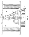
- a so-called "ultracentrifuge” is illustrated.
- a motor M spins a rotor R about an axis A. High speeds are involved. It is not uncommon for rotor R to spin at 100,000 revolutions/minute. As is well known in the art, centrifuging occurs in a vacuum to avoid windage.
- a sample is contained within a cell S1.
- the cell includes an upper window 20 and a lower window 22 permitting light to pass parallel to the spin axis of rotor R. It is through these respective windows that a light sample formed in accordance with the teaching of this invention performs the method of examining sample stratification while centrifuging dynamically occurs.
- detector D is a moving slit capable of having excursion over the radial length of the sample.
- sample is typically disposed at a sample point P when the sample is optically read for stratification.
- Sample point P lies along a radius 26 from the spin axis A of the centrifuge.
- a sample plane includes the spin axis A and the radius 26 extending from the spin axis through the point of sample. This sample plane is the plane in which the light collimation occurs. This same sample plane is the plane of Fig. 4.
- This plane is the dispersion plane and is the plane along which chromatic dispersion of light occurs. Collimation of light does not occur in the dispersion plane.
- This dispersion plane is the plane of the illustration of Fig. 3.
- the function of the specialized optics of this invention can be set forth. This function will include first the collimation of the light to produce the desired examination of the strata along the sample plane. Secondly, the chromatic classification of the light will be discussed with respect to the dispersion plane. Finally, and with reference to Fig. 5. the resolution characteristics of the invention will be set forth.
- a strobed light source L passes an aperture 28 preferably 1 mm or less in diameter.
- Light 40 from the light source passes respective tube stops 30 and 32 and is incident upon mirror M.
- Fig. 4 the reader will understand that light source L is not shown, Fig. 4, however, does show light 40 emanating downwardly from mirror M through sample 50 past a slit detector 52 and to and upon a detector D. It will be understood that slit 52 scans underneath the sample 50. In such scanning it will identify strata precisely parallel to spin axis A and normal to the sample plane of Fig. 4.
- Mirror M is here shown given a cylindrical shape with respect to light source L in the sample plane of Fig. 4. This cylindrical shape is chosen so that rays 40 are precisely collimated within the plane of Fig. 4 along a path parallel to the spin axis of rotor R. Thus, any classified layers of sediment such as that existing at band B have the collimated rays 40 past precisely parallel to and through the band B.
- Mirror M is shaped along one axis for the generation of the collimated rays. Along the other axis, the mirror is provided with a different curvature and differently spaced rulings so that tilting of the mirror produces light of varying color.
- Rotation of grating to change wavelength occurs about 30° from normal to the light source. Effective curvature for collimation does not charge regardless of grating angle.
- slit 52 traverses the detector D back and forth along the path indicated by double arrow 54.
- detector D will see the differences in the receipt of light as described in Cohen U.S. Patent 3,712,742 issued January 23, 1973.
- light source L is typically a strobed zenon source. At the instant of strobing the light source includes output in the range of 20,000 watts.
- mirror M is provided with curvatures having unequal spaced rulings in the plane of Fig. 4. As viewed in Fig. 3, the rulings extend into and out of the plane of the drawing.
- scanning of sample 50 can occur in 5 nanometer wide bands.
- the width of the scanning optical bands or band pass is in effect determined by the solid angle of mirror radiation defined through windows 20, 22 as viewed in Figs. 3 and 4.
- Serendipity is present from such scanning.
- the band of chromatically classified light is parallel to and in the plane of the band B as shown in Fig. 4.
- both the-band B and its respective surfaces are illuminated with light.
- the illuminating light is in the order of ten times that light which would be available had the light been collimated with respect to both the planes of Figs. 3 and 4.
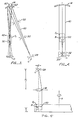
- FIG. 5 an optical schematic of the system is illustrated. This schematic demonstrates how the length of the folded light path illustrated in Figs. 3 and 4 assists in the band resolution of the sample.
- the distance X1 represents the effective length of the optical path between the light L and the sample S1. This distance is equal to about 33 cm.
- the distance X2 is the distance between the slit 52 and the sample S1. This distance is about 2 cm. It will be observed that the folded light path X1 is very much longer than the path X2. Therefore. the slit 52 will see the banding B at a high resolution where: d2 X2 ⁇ d1 X1
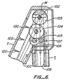
- FIG. 6 the optical tube in the vicinity of the mirror schematically shown in Figs. 3 and 4 is illustrated.
- the mirror is shown in the same plane as the schematic of Fig. 4.
- Optical baffles eliminate all portions of the beam from light L (See Fig. 1) save and except that light which will impact mirror M. Light is reflected from mirror M and passes down tube T1 to sample the contents of a rotating cell.
- Mirror M pivots about a pivot 102.
- the mirror is driven in such pivotal motion by a gear train including gears 103, 104.
- This gear train also includes reduction gears 105, 106, an idler gear 107 which is finally driven by a rack 108.
- rack 108 As can be readily understood, by linear motion of rack 108 towards and away from the mirror, finely adjusted and precise rotation of mirror M can occur. Since the mirror always collimates, change in angle of the mirror will only affect the color doing the sampling at the rotating cell.
- the ability to rapidly change color enables the rapid adjustment of the color for sampling the classified materials within the cell.
- the photodetector passes over the radius of an individual cell, the color of the sampling light can be rapidly changed for optimum detection of classified strata having varying optical densities.
- slit 52 and the detector D as shown in Fig. 4 has an additional advantage that is not apparent. Specifically, as sample S1 is increasing classified, various components of the sample will settle out at discrete layers. These components can include various salts.
- slit 52 has an active width of approximately 0.1 millimeter and is spaced with respect to the active surface of detector D so that a plus or minus 2 degree from the vertical angular view of the sample is obtained.
Landscapes
- Physics & Mathematics (AREA)
- Spectroscopy & Molecular Physics (AREA)
- General Physics & Mathematics (AREA)
- Chemical & Material Sciences (AREA)
- Dispersion Chemistry (AREA)
- Health & Medical Sciences (AREA)
- Life Sciences & Earth Sciences (AREA)
- Analytical Chemistry (AREA)
- Biochemistry (AREA)
- General Health & Medical Sciences (AREA)
- Immunology (AREA)
- Pathology (AREA)
- Investigating Or Analysing Materials By Optical Means (AREA)
- Centrifugal Separators (AREA)
- Optical Measuring Cells (AREA)
Applications Claiming Priority (2)
| Application Number | Priority Date | Filing Date | Title |
|---|---|---|---|
| US07/115,023 US4830493A (en) | 1987-10-29 | 1987-10-29 | UV scanning system for centrifuge |
| US115023 | 1987-10-29 |
Publications (2)
| Publication Number | Publication Date |
|---|---|
| EP0340279A1 EP0340279A1 (en) | 1989-11-08 |
| EP0340279B1 true EP0340279B1 (en) | 1992-08-26 |
Family
ID=22358870
Family Applications (1)
| Application Number | Title | Priority Date | Filing Date |
|---|---|---|---|
| EP88909862A Expired EP0340279B1 (en) | 1987-10-29 | 1988-10-20 | Uv scanning system for centrifuge |
Country Status (8)
| Country | Link |
|---|---|
| US (1) | US4830493A (2) |
| EP (1) | EP0340279B1 (2) |
| JP (1) | JPH0742121Y2 (2) |
| CN (1) | CN1011554B (2) |
| CA (1) | CA1295031C (2) |
| DE (1) | DE3874125T2 (2) |
| HU (1) | HU206771B (2) |
| WO (1) | WO1989003986A1 (2) |
Families Citing this family (26)
| Publication number | Priority date | Publication date | Assignee | Title |
|---|---|---|---|---|
| US4921350A (en) * | 1989-02-10 | 1990-05-01 | Beckman Instruments, Inc. | Monochromator second order subtraction method |
| US5123740A (en) * | 1991-01-15 | 1992-06-23 | Beckman Instruments, Inc. | Stray light trap in a monochrometer |
| GB9302673D0 (en) * | 1993-02-11 | 1993-03-24 | Haematest Limited | Apparatus for analysing blood and other samples |
| US5563333A (en) * | 1995-01-20 | 1996-10-08 | Haines; Hiemi K. | Method and apparatus for core flooding studies |
| US7173551B2 (en) | 2000-12-21 | 2007-02-06 | Quellan, Inc. | Increasing data throughput in optical fiber transmission systems |
| US7307569B2 (en) * | 2001-03-29 | 2007-12-11 | Quellan, Inc. | Increasing data throughput in optical fiber transmission systems |
| US7149256B2 (en) * | 2001-03-29 | 2006-12-12 | Quellan, Inc. | Multilevel pulse position modulation for efficient fiber optic communication |
| IL158211A0 (en) * | 2001-04-04 | 2004-05-12 | Quellan Inc | Method and system for decoding multilevel signals |
| US20030030873A1 (en) * | 2001-05-09 | 2003-02-13 | Quellan, Inc. | High-speed adjustable multilevel light modulation |
| WO2003071731A1 (en) * | 2002-02-15 | 2003-08-28 | Quellan, Inc. | Multi-level signal clock recovery technique |
| US6816101B2 (en) * | 2002-03-08 | 2004-11-09 | Quelian, Inc. | High-speed analog-to-digital converter using a unique gray code |
| AU2003223687A1 (en) * | 2002-04-23 | 2003-11-10 | Quellan, Inc. | Combined ask/dpsk modulation system |
| JP2004013681A (ja) * | 2002-06-10 | 2004-01-15 | Bosu & K Consulting Kk | 名刺情報管理システム |
| US7035361B2 (en) * | 2002-07-15 | 2006-04-25 | Quellan, Inc. | Adaptive noise filtering and equalization for optimal high speed multilevel signal decoding |
| AU2003287628A1 (en) * | 2002-11-12 | 2004-06-03 | Quellan, Inc. | High-speed analog-to-digital conversion with improved robustness to timing uncertainty |
| JP2007502054A (ja) * | 2003-08-07 | 2007-02-01 | ケラン インコーポレイテッド | クロストークキャンセルのための方法とシステム |
| US7804760B2 (en) * | 2003-08-07 | 2010-09-28 | Quellan, Inc. | Method and system for signal emulation |
| ATE488068T1 (de) * | 2003-11-17 | 2010-11-15 | Quellan Inc | Verfahren und system zur löschung von antennenstörungen |
| US7616700B2 (en) * | 2003-12-22 | 2009-11-10 | Quellan, Inc. | Method and system for slicing a communication signal |
| US7209230B2 (en) | 2004-06-18 | 2007-04-24 | Luckoff Display Corporation | Hand-held spectra-reflectometer |
| US7725079B2 (en) * | 2004-12-14 | 2010-05-25 | Quellan, Inc. | Method and system for automatic control in an interference cancellation device |
| US7522883B2 (en) * | 2004-12-14 | 2009-04-21 | Quellan, Inc. | Method and system for reducing signal interference |
| US20100239436A1 (en) * | 2005-05-17 | 2010-09-23 | Honeywell International Inc. | A thermal pump |
| US7233394B2 (en) | 2005-06-20 | 2007-06-19 | Luckoff Display Corporation | Compact spectrometer |
| WO2007127369A2 (en) * | 2006-04-26 | 2007-11-08 | Quellan, Inc. | Method and system for reducing radiated emissions from a communications channel |
| US20230330686A1 (en) * | 2022-04-18 | 2023-10-19 | Fenwal, Inc. | Interface Detection And Control Using A Photodetector Array |
Family Cites Families (12)
| Publication number | Priority date | Publication date | Assignee | Title |
|---|---|---|---|---|
| FR2036613A5 (2) * | 1969-03-26 | 1970-12-24 | Jobin Et G Yvon | |
| GB1256269A (en) * | 1969-06-27 | 1971-12-08 | Mse Holdings Ltd | Centrifuge |
| FR2055891A5 (2) * | 1969-08-05 | 1971-05-14 | Anvar | |
| FR2096982B1 (2) * | 1970-07-23 | 1974-06-14 | Jobin & Yvon | |
| US3807874A (en) * | 1972-03-31 | 1974-04-30 | Beckman Instruments Inc | Optical system for centrifuges |
| US3973850A (en) * | 1972-04-21 | 1976-08-10 | Agence Nationale De Valorisation De La Recherche (Anvar) | Focalization process of spherical concave diffraction gratings |
| FR2239674B1 (2) * | 1973-08-03 | 1976-04-30 | Jobin & Yvon | |
| FR2240445B2 (2) * | 1973-08-06 | 1976-05-07 | Jobin & Yvon | |
| FR2271586B1 (2) * | 1973-11-29 | 1978-03-24 | Instruments Sa | |
| US4285596A (en) * | 1977-08-16 | 1981-08-25 | Neotec Corporation | Holographic diffraction grating system for rapid scan spectral analysis |
| CH647598A5 (en) * | 1980-01-14 | 1985-01-31 | Haakon Trygve Jun Magnussen | Spectral photometer for carrying out a spectral analysis |
| JPS5761934A (en) * | 1980-09-30 | 1982-04-14 | Hitachi Koki Co Ltd | Scanning apparatus of light absorption of ultracentrifuge in common use of separation and analysis |
-
1987
- 1987-10-29 US US07/115,023 patent/US4830493A/en not_active Expired - Lifetime
-
1988
- 1988-10-13 CA CA000580040A patent/CA1295031C/en not_active Expired - Lifetime
- 1988-10-20 WO PCT/US1988/003683 patent/WO1989003986A1/en not_active Ceased
- 1988-10-20 EP EP88909862A patent/EP0340279B1/en not_active Expired
- 1988-10-20 HU HU886712A patent/HU206771B/hu not_active IP Right Cessation
- 1988-10-20 JP JP1990600002U patent/JPH0742121Y2/ja not_active Expired - Lifetime
- 1988-10-20 DE DE8888909862T patent/DE3874125T2/de not_active Expired - Fee Related
- 1988-10-29 CN CN88109257.6A patent/CN1011554B/zh not_active Expired
Also Published As
| Publication number | Publication date |
|---|---|
| EP0340279A1 (en) | 1989-11-08 |
| HU206771B (en) | 1992-12-28 |
| CN1039123A (zh) | 1990-01-24 |
| CA1295031C (en) | 1992-01-28 |
| DE3874125T2 (de) | 1993-04-08 |
| CN1011554B (zh) | 1991-02-06 |
| HU886712D0 (en) | 1990-09-28 |
| DE3874125D1 (de) | 1992-10-01 |
| US4830493A (en) | 1989-05-16 |
| HUT53736A (en) | 1990-11-28 |
| JPH02500028U (2) | 1990-07-05 |
| WO1989003986A1 (en) | 1989-05-05 |
| JPH0742121Y2 (ja) | 1995-09-27 |
Similar Documents
| Publication | Publication Date | Title |
|---|---|---|
| EP0340279B1 (en) | Uv scanning system for centrifuge | |
| JP4455730B2 (ja) | 多走査ビーム反射率を用いる粒子評価のための方法および装置 | |
| JP4382098B2 (ja) | 分析方法および分析装置 | |
| US5623342A (en) | Raman microscope | |
| US3975084A (en) | Particle detecting system | |
| EP1520173B1 (en) | Optical projection tomography | |
| JP4097085B2 (ja) | 蛍光光度計 | |
| JPH03504046A (ja) | ラマン分析装置 | |
| EP0222831A1 (en) | Automated refractometer | |
| JP7612351B2 (ja) | 識別装置 | |
| KR100203345B1 (ko) | 동시 다중각/다중파장 타원편광계와 측정방법 | |
| JPH11316344A (ja) | 共焦点の顕微分光計システム | |
| US4922104A (en) | Infrared microspectrometer | |
| EP1370850B1 (en) | Apparatus and method for total internal reflection spectroscopy | |
| US4919537A (en) | UV scanning system for centrifuge | |
| JPH0812144B2 (ja) | 沈降中にスペクトル光吸収測定により粒度分布を求める方法および装置 | |
| US4921350A (en) | Monochromator second order subtraction method | |
| US11614397B2 (en) | Identification apparatus and identification method | |
| US6873412B2 (en) | Method and device for suppressing multiple scattering when examining turbid media by means of three-dimensional cross-correlation technique | |
| DE19515870C1 (de) | Vorrichtung zur Trennung von Medien in deren Bestandteile | |
| KR102622581B1 (ko) | 마이크로스폿 분광타원계가 구비된 반도체 ocd 측정장치 | |
| JP4336847B2 (ja) | 顕微分光測定装置 | |
| US12158425B2 (en) | Adjustable extended focus raman system | |
| Brenan et al. | Confocal image properties of a confocal scanning laser visible light FT-Raman microscope | |
| FR2685789A1 (fr) | Microscope en champ proche fonctionnant par detection tunnel optique. |
Legal Events
| Date | Code | Title | Description |
|---|---|---|---|
| PUAI | Public reference made under article 153(3) epc to a published international application that has entered the european phase |
Free format text: ORIGINAL CODE: 0009012 |
|
| AK | Designated contracting states |
Kind code of ref document: A1 Designated state(s): CH DE FR GB IT LI SE |
|
| 17P | Request for examination filed |
Effective date: 19891030 |
|
| 17Q | First examination report despatched |
Effective date: 19910201 |
|
| GRAA | (expected) grant |
Free format text: ORIGINAL CODE: 0009210 |
|
| ITF | It: translation for a ep patent filed | ||
| AK | Designated contracting states |
Kind code of ref document: B1 Designated state(s): CH DE FR GB IT LI SE |
|
| PG25 | Lapsed in a contracting state [announced via postgrant information from national office to epo] |
Ref country code: SE Free format text: THE PATENT HAS BEEN ANNULLED BY A DECISION OF A NATIONAL AUTHORITY Effective date: 19920826 Ref country code: LI Effective date: 19920826 Ref country code: CH Effective date: 19920826 |
|
| REF | Corresponds to: |
Ref document number: 3874125 Country of ref document: DE Date of ref document: 19921001 |
|
| REG | Reference to a national code |
Ref country code: CH Ref legal event code: PL |
|
| ET | Fr: translation filed | ||
| PLBE | No opposition filed within time limit |
Free format text: ORIGINAL CODE: 0009261 |
|
| STAA | Information on the status of an ep patent application or granted ep patent |
Free format text: STATUS: NO OPPOSITION FILED WITHIN TIME LIMIT |
|
| 26N | No opposition filed | ||
| PGFP | Annual fee paid to national office [announced via postgrant information from national office to epo] |
Ref country code: GB Payment date: 19990913 Year of fee payment: 12 |
|
| PGFP | Annual fee paid to national office [announced via postgrant information from national office to epo] |
Ref country code: FR Payment date: 19991013 Year of fee payment: 12 |
|
| PGFP | Annual fee paid to national office [announced via postgrant information from national office to epo] |
Ref country code: DE Payment date: 19991027 Year of fee payment: 12 |
|
| PG25 | Lapsed in a contracting state [announced via postgrant information from national office to epo] |
Ref country code: GB Free format text: LAPSE BECAUSE OF NON-PAYMENT OF DUE FEES Effective date: 20001020 |
|
| GBPC | Gb: european patent ceased through non-payment of renewal fee |
Effective date: 20001020 |
|
| PG25 | Lapsed in a contracting state [announced via postgrant information from national office to epo] |
Ref country code: FR Free format text: LAPSE BECAUSE OF NON-PAYMENT OF DUE FEES Effective date: 20010629 |
|
| PG25 | Lapsed in a contracting state [announced via postgrant information from national office to epo] |
Ref country code: DE Free format text: LAPSE BECAUSE OF NON-PAYMENT OF DUE FEES Effective date: 20010703 |
|
| REG | Reference to a national code |
Ref country code: FR Ref legal event code: ST |
|
| PG25 | Lapsed in a contracting state [announced via postgrant information from national office to epo] |
Ref country code: IT Free format text: LAPSE BECAUSE OF NON-PAYMENT OF DUE FEES Effective date: 20051020 |