EP0340191B1 - A method and an apparatus for joining together two elements included in an implant and/or prosthesis structure - Google Patents
A method and an apparatus for joining together two elements included in an implant and/or prosthesis structure Download PDFInfo
- Publication number
- EP0340191B1 EP0340191B1 EP89850129A EP89850129A EP0340191B1 EP 0340191 B1 EP0340191 B1 EP 0340191B1 EP 89850129 A EP89850129 A EP 89850129A EP 89850129 A EP89850129 A EP 89850129A EP 0340191 B1 EP0340191 B1 EP 0340191B1
- Authority
- EP
- European Patent Office
- Prior art keywords
- devices
- elements
- laser
- joint
- welding
- Prior art date
- Legal status (The legal status is an assumption and is not a legal conclusion. Google has not performed a legal analysis and makes no representation as to the accuracy of the status listed.)
- Expired - Lifetime
Links
- 238000005304 joining Methods 0.000 title claims abstract description 9
- 239000007943 implant Substances 0.000 title claims abstract description 7
- 238000000034 method Methods 0.000 title claims description 22
- 238000003466 welding Methods 0.000 claims abstract description 55
- 230000003287 optical effect Effects 0.000 claims abstract description 21
- 239000000463 material Substances 0.000 claims abstract description 18
- 230000008569 process Effects 0.000 claims description 13
- 239000000758 substrate Substances 0.000 claims description 8
- RTAQQCXQSZGOHL-UHFFFAOYSA-N Titanium Chemical compound [Ti] RTAQQCXQSZGOHL-UHFFFAOYSA-N 0.000 claims description 5
- 229910052719 titanium Inorganic materials 0.000 claims description 5
- 239000010936 titanium Substances 0.000 claims description 5
- 238000006073 displacement reaction Methods 0.000 claims description 3
- 238000007689 inspection Methods 0.000 claims 1
- 230000014759 maintenance of location Effects 0.000 description 6
- 238000004519 manufacturing process Methods 0.000 description 6
- 230000004913 activation Effects 0.000 description 5
- 230000005855 radiation Effects 0.000 description 4
- 238000005520 cutting process Methods 0.000 description 3
- 239000000835 fiber Substances 0.000 description 3
- 230000007246 mechanism Effects 0.000 description 3
- 210000004268 dentin Anatomy 0.000 description 2
- 239000012190 activator Substances 0.000 description 1
- 230000006978 adaptation Effects 0.000 description 1
- 239000000853 adhesive Substances 0.000 description 1
- 230000001070 adhesive effect Effects 0.000 description 1
- 230000005540 biological transmission Effects 0.000 description 1
- 230000008859 change Effects 0.000 description 1
- 238000010276 construction Methods 0.000 description 1
- 230000001419 dependent effect Effects 0.000 description 1
- 238000002845 discoloration Methods 0.000 description 1
- 230000000694 effects Effects 0.000 description 1
- 238000005498 polishing Methods 0.000 description 1
- 230000000717 retained effect Effects 0.000 description 1
Images
Classifications
-
- B—PERFORMING OPERATIONS; TRANSPORTING
- B23—MACHINE TOOLS; METAL-WORKING NOT OTHERWISE PROVIDED FOR
- B23K—SOLDERING OR UNSOLDERING; WELDING; CLADDING OR PLATING BY SOLDERING OR WELDING; CUTTING BY APPLYING HEAT LOCALLY, e.g. FLAME CUTTING; WORKING BY LASER BEAM
- B23K26/00—Working by laser beam, e.g. welding, cutting or boring
- B23K26/02—Positioning or observing the workpiece, e.g. with respect to the point of impact; Aligning, aiming or focusing the laser beam
- B23K26/06—Shaping the laser beam, e.g. by masks or multi-focusing
- B23K26/067—Dividing the beam into multiple beams, e.g. multifocusing
- B23K26/0676—Dividing the beam into multiple beams, e.g. multifocusing into dependently operating sub-beams, e.g. an array of spots with fixed spatial relationship or for performing simultaneously identical operations
-
- A—HUMAN NECESSITIES
- A61—MEDICAL OR VETERINARY SCIENCE; HYGIENE
- A61C—DENTISTRY; APPARATUS OR METHODS FOR ORAL OR DENTAL HYGIENE
- A61C13/00—Dental prostheses; Making same
- A61C13/20—Methods or devices for soldering, casting, moulding or melting
-
- B—PERFORMING OPERATIONS; TRANSPORTING
- B23—MACHINE TOOLS; METAL-WORKING NOT OTHERWISE PROVIDED FOR
- B23K—SOLDERING OR UNSOLDERING; WELDING; CLADDING OR PLATING BY SOLDERING OR WELDING; CUTTING BY APPLYING HEAT LOCALLY, e.g. FLAME CUTTING; WORKING BY LASER BEAM
- B23K26/00—Working by laser beam, e.g. welding, cutting or boring
- B23K26/02—Positioning or observing the workpiece, e.g. with respect to the point of impact; Aligning, aiming or focusing the laser beam
- B23K26/06—Shaping the laser beam, e.g. by masks or multi-focusing
- B23K26/067—Dividing the beam into multiple beams, e.g. multifocusing
-
- B—PERFORMING OPERATIONS; TRANSPORTING
- B23—MACHINE TOOLS; METAL-WORKING NOT OTHERWISE PROVIDED FOR
- B23K—SOLDERING OR UNSOLDERING; WELDING; CLADDING OR PLATING BY SOLDERING OR WELDING; CUTTING BY APPLYING HEAT LOCALLY, e.g. FLAME CUTTING; WORKING BY LASER BEAM
- B23K26/00—Working by laser beam, e.g. welding, cutting or boring
- B23K26/20—Bonding
- B23K26/21—Bonding by welding
- B23K26/22—Spot welding
Definitions
- the present invention relates to a method of joining together, at least substantially distortion-free, two elements of a hard material, preferably of titanium, and included in a structure for implants and/or prostheses.
- a structure for implants and/or prostheses examples of structures of the type contemplated here are dental prosthetic bridges, dental crown arrangements, joint components, other prosthetic parts etc.
- the process comprises a first part process in which two reciprocally disposable contact surfaces are accurately registered and fixed to one another via a joint, and a second part process in which the joining together proper takes place by means of welding using laser equipment.
- the invention also relates to an apparatus for carrying the novel method into effect.
- the model is designed with anchorage means for the modular elements and the anchorage means correspond with extreme accuracy in their positioning and extent to the actual positions of the anchorage means (pins) implanted in the patient's mouth.
- the object of the present invention is to propose a novel process and a novel apparatus resolving the above and other problems.
- the novel process according to the present invention is characterized in that the elements are disposed with registering circumferential portions, for instance sides, on the joint, exposed to two focusing optical devices which emit laser pulses or laser beams and form part of the laser equipment. At the registering joint circumferential portions, the devices are then each aimed at one of two substantially registering, or slightly mutually, offset starting areas which each include their section of each respective joint circumferential portion with circumjacent material parts on the elements.
- the laser equipment is energized to emit, via the devices, the above-mentioned laser pulses or laser beams while the elements and devices are mutually influenced for attaining laser power emission towards the starting areas and the subsequent areas with associated sections of the joint circumferential portions and material parts. In such instance, the devices may be operative to emit their laser pulses or laser beams simultaneously or alternatingly.
- the elements are secured and fixed with the contact surfaces in abutment against one another in a positive model which is utilized as fixing tool.
- the model is secured on an adjustable, for example vertically adjustable, surface which, on laser power emission, is actuated in relation to the focusing optical devices which, in this instance, are disposed (fixedly clamped) in relation to the surface.
- the mutual control between the elements and the devices is preferably carried out under simultaneous ocular scanning of the elements, joints and devices.
- the mutual movements between the elements and devices are controlled such that the devices are first aimed towards a relevant area and, thereafter, the laser pulses for the welding operation are emitted.
- zig-zag spot welding may be carried out, i.e.
- welding takes place only on the one side and, on advancement to a subsequent area, welding takes place only on the other side, and so on.
- welding may be effected first with the one device and then with the other device before mutual movement takes place between the elements and the devices.
- the novel apparatus according to the present invention may be considered as characterized, int. al., in that two focusing optical devices are disposed to be aligned each from their side towards registering circumferential portions (sides) of the joint when the elements, in the adapted and fixed state, are applied to an application substrate.
- the afore-mentioned focusing optical devices and application substrate are mutually displaceably controlled so that the focusing devices are first aligned towards two substantially registering, or slightly mutually offset starting areas which each include their section of each respective joint circumferential portion with circumjacent material parts on the elements, and thereafter are stepwise or continually aligned towards areas subsequent to the starting areas and with associated sections of joint circumferential portions and material parts.
- the laser equipment is disposed, in conjunction with the displacement control, to emit operational laser pulses or laser beams.
- the focusing optical devices are fixedly disposed in relation to the application substrate, which, in its turn, is controlled in relation to the devices in one or more directions, for example in the vertical direction.
- the apparatus is preferably of the type which includes magnification devices by means of which the alignment towards the different areas is controlled, at the same time as the joint and the welding process proper may be monitored.
- Advancement to the different welding points or areas may be carried out stepwise and the laser pulse emission may be effectuated after each respective advancement step.
- the laser pulse emission may be performed simultaneously from the focusing optical devices.
- zig-zag spot welding may be carried out, i.e. the first device is activated to emit laser pulses every second time and the second focusing optical device is activated to emit laser pulses every second time, in which event the welding spots at both sides (or their equivalent) of the joint will be offset one step.
- continuous laser beam emission may be effectuated.
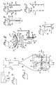
- the apparatus includes a per se known machine 1 which is provided with a moving table 2.
- the table is displaceable along the X and Y axes with the aid of activation means (of micrometer screw type) 3 and 4, respectively.
- the directions of activation are indicated by means of arrows 5 and 6, respectively.
- the table is carried in a machine frame 1a in a per se known manner.
- a positive working model 9 of per se known type is secured to the table by means of retention members 7, 8.
- the working model constitutes a positive copy of a dentine impression.
- a multiple component bridge is to be produced with the aid of the model and is constructed from prefabricated modular elements 10, 11.
- the modular elements may vary in number between two or more and may be substantially identical or mutually different.
- every other modular element 10 is fixedly secured in a known manner in the working model with the aid of retention members 12, for instance in the form of a screw.
- the screw is screwed in place in retention members in the model 9, these retention members corresponding in their location and extent to implanted pins in the dentine of the patient.
- every other element 11 is in the form of a beam-like element which, via end surfaces, may be fixedly welded in the first-mentioned modular element 10.
- the equipment according to Fig. 1 also includes per se known laser welding equipment with a laser source 13 and with focusing optical devices 14, 15 which are connected to a radiation distributor 16 which, in turn, is connected to the laser source 13 by means of a connection 17.
- the connection between the radiation distributor and the devices comprises optical fibres 18 and 19 which, hence, are flexible.
- two devices 14 and 15 are employed. Indeed, it is possible to employ a greater number of devices connected to the unit 16 in a corresponding manner.
- two laser sources 13 may be employed, each being provided with its own focusing optical device.
- such focusing optical devices and connections 18, 19 are employed as provide for high power transmission with relatively slight cross-sectional area of the optic fibre.
- Fibre optic devices with such connections 18 or 19 are readily available on the market.
- jointed optical connections rigid conductive sections connected at articulated points).
- the devices are anchorably disposed in connection with the machine 1.
- the anchorage may be fixedly secured with the aid of per se known jigs and locking means (screws).
- these jigs are schematically indicated by reference numerals 20, 21; and 22, 23.
- Fig. 2 shows the equipment according to Fig. 1 in vertical section.
- the devices 14, 15 may also be vertically adjusted, the jigs in this case being indicated by reference numerals 24, 25.
- By the locking arrangement for the devices 14, 15, these may be fixedly disposed in relation to the table 2 which, according to Fig. 2, is also adjustable in the vertical direction 26.
- the retention devices 7, 8 may consist of clamps or the like. In Fig. 2, the retention device 7 has been partly eliminated for purposes of clarity.
- Vertical control may be effected in a per se known manner with the aid of a lever 27 for manual activation.
- a shaft 28 is fixedly secured to the lever, and a gearwheel 29 (partly concealed in Fig. 2) is non-rotatably disposed thereon and engages with a gear rack 30.
- This latter is fixedly disposed on a column 2a of the table 2.
- vertical directional control of the table 2 may be effected by means of a stepping motor 31, on whose output shaft there is disposed a gearwheel which is in engagement with the above-mentioned gear rack 30.
- the equipment 1 may also be provided, in a known manner, with magnification devices which, in Fig. 2, are represented by their optical portions 33.
- the elements 10, 11 are, thus, displaceably disposed in relation to the devices 14, 15.
- the system may be arranged such that the devices 14, 15 are movable in relation to fixedly disposed elements (the table 2).
- the focusing optical devices may be aligned each towards their side 10a, 10b, respectively of the elements/joints between the elements 10, 11.
- the front ends of the devices have been indicated by reference numerals 14a and 15a respectively.
- the devices are set so close to the joint 34 (Fig. 1) that an optimum distance for the welding will be obtained at each respective welding point.
- the case as illustrated in Figs. 1 and 2 relates to modular elements 10, 11 with vertically extending side surfaces 10a, 10b and joint sides.
- optimum welding may be effected along the entire length of the joint, in that the table 2 is activated in the vertical direction while welding is in progress.
- the joints/element sides are of different extents, the mutual movement between the elements and the devices must be controlled correspondingly.
- the basic requirement for the relative guiding between the elements and the devices is that the devices must always assume an optimum distance in relation to the joint.
- Fig. 3 is intended to show welding points or "spots" along the joint.
- the points or spots form regions or areas which each encompass a joint side portion and circumjacent material on the elements 10, 11.
- the starting area is shown by reference numeral 35.
- the starting area encompasses a joint side portion 34a and material regions 10c and 11b respectively.
- the region 35 which may also be considered as representing the starting spot from the device 14, 15 in question, should in principle be as small as possible (i.e. the departing light beam from the device should be of high concentration).
- the welding operation proceeds such that each respective device is aimed at a starting area which may consist of the area 35.
- Laser pulse emission then takes place against the aligned portion, which entails that a welding point occurs.
- the mutual position between the elements and the devices is influenced such that alignment of the device in question takes place towards a subsequent area 36, with consequential laser pulse emission, and so on until the entire joint has progressively been spot welded.
- the welding operation is to be effected in coordination on both sides 34b and 34c respectively of the joint.
- the device 14a caters for the welding function on side 34b
- the device 15a caters for the welding on side 34c.
- the device tips 14a and 15a respectively have been shown as disposed adjacent the areas 35 and 35′.
- the relative positional change has been indicated by reference numerals 14a′ and 15a′ respectively, having then been disposed adjacent the areas 36, 36′
- activation of the laser equipment/devices 14, 15 takes place simultaneously, entailing that two welding points located in register with one another will be obtained simultaneously at the joint.
- the welding point 35 may be welded before welding point 35′, or vice versa.
- FIG. 5 shows the depth a of the joint 35.
- joint depths of approx. 0.4 mm are desirable in a width B of the elements of, for instance, 2.0 mm.
- the contact surfaces are indicated by reference numerals 10d and 11c.
- the modular elements may have other cross-sectional configurations than rectangular or quadratic.
- Fig. 7 shows that the impulse emission from the laser equipment/devices 14, 15 may be effected as soon as advancement to a new region 35, 36 has taken place.
- the advancement mechanism which may be connected to the lever 27 or the motor 31, emits, in each advanced position, a triggering signal to the laser equipment which is activated to emit its impulse in each respective advanced position. Activation of the laser equipment may take place independently of the mutual displacement influenced between the elements and the devices. Alternatively, the laser equipment may be activated by a manual activator 37.
- the afore-mentioned advancement mechanism is indicated by reference numeral 38.
- the joint is first prepared by being ground in a fixture.
- the gap should be 0 or as small as possible. All edges must be sharp. Joints in which the gap at any point exceeds a certain level, for instance 0.1 mm, must be reground so that the requirement of joints which are less than the predetermined value, i.e. 0.1 mm, is satisfied.
- Loose beams are secured to the model using plastic adhesive (not wax). Possibly contaminated welding surfaces must be washed before the welding operation is carried out.
- the laser parameters are checked before commencement of the welding operation, and this may be effected by welding a test rod in a specifically allocated tool. The rods are designed with smooth-ground end surfaces. The thus executed welding is inspected and any possible adjustment to the laser parameters is then carried out.
- the modular elements or the bridge are mounted in the welding fixture (the working model). All joints are inspected through the microscope and/or on a TV monitor connected to the equipment. As in all laser welding, use is also made here of a shielding gas during the welding. In such instance, it is vital to ensure that the shielding gas covers all welding points in a known manner. The welding may thereafter proceed.
- the finished bridge is inspected on both sides in the microscope in respect of cracks, porosity, depressions and discoloration. The screws 12 are removed and the fit is checked.
- continuous or substantially stepless laser radiation welding is employed via each respective device 14 and 15 during the above-mentioned simultaneous mutual guiding of the devices and the element 10, 11, such guiding being, in this case, continuous.
Landscapes
- Physics & Mathematics (AREA)
- Optics & Photonics (AREA)
- Engineering & Computer Science (AREA)
- Plasma & Fusion (AREA)
- Mechanical Engineering (AREA)
- Health & Medical Sciences (AREA)
- Animal Behavior & Ethology (AREA)
- Veterinary Medicine (AREA)
- Epidemiology (AREA)
- Life Sciences & Earth Sciences (AREA)
- Oral & Maxillofacial Surgery (AREA)
- General Health & Medical Sciences (AREA)
- Public Health (AREA)
- Dentistry (AREA)
- Laser Beam Processing (AREA)
- Prostheses (AREA)
- Coupling Device And Connection With Printed Circuit (AREA)
- Connections Effected By Soldering, Adhesion, Or Permanent Deformation (AREA)
- Lining Or Joining Of Plastics Or The Like (AREA)
- Dental Prosthetics (AREA)
Priority Applications (1)
| Application Number | Priority Date | Filing Date | Title |
|---|---|---|---|
| AT89850129T ATE80078T1 (de) | 1988-04-28 | 1989-04-24 | Verfahren und vorrichtung zum verbinden zweier teile innerhalb einer inplantierungs- und/oder prothesestruktur. |
Applications Claiming Priority (2)
| Application Number | Priority Date | Filing Date | Title |
|---|---|---|---|
| SE8801601A SE458991B (sv) | 1988-04-28 | 1988-04-28 | Foerfarande och anordning foer att distorsionsfritt sammanfoga tvaa i en implantatskonstruktion och/eller protetisk konstruktion ingaaende element |
| SE8801601 | 1988-04-28 |
Publications (3)
| Publication Number | Publication Date |
|---|---|
| EP0340191A2 EP0340191A2 (en) | 1989-11-02 |
| EP0340191A3 EP0340191A3 (en) | 1990-08-08 |
| EP0340191B1 true EP0340191B1 (en) | 1992-09-02 |
Family
ID=20372165
Family Applications (1)
| Application Number | Title | Priority Date | Filing Date |
|---|---|---|---|
| EP89850129A Expired - Lifetime EP0340191B1 (en) | 1988-04-28 | 1989-04-24 | A method and an apparatus for joining together two elements included in an implant and/or prosthesis structure |
Country Status (8)
| Country | Link |
|---|---|
| US (1) | US5059758A (OSRAM) |
| EP (1) | EP0340191B1 (OSRAM) |
| JP (1) | JP2824782B2 (OSRAM) |
| AT (1) | ATE80078T1 (OSRAM) |
| DE (1) | DE68902676T2 (OSRAM) |
| ES (1) | ES2034761T3 (OSRAM) |
| GR (1) | GR3006080T3 (OSRAM) |
| SE (1) | SE458991B (OSRAM) |
Families Citing this family (10)
| Publication number | Priority date | Publication date | Assignee | Title |
|---|---|---|---|---|
| FR2702406B1 (fr) * | 1993-03-12 | 1997-05-30 | Laurent Pinto | Machine et procede pour l'assemblage particulier de pieces de precision par soudage-diffusion par contre reaction. |
| JPH08263784A (ja) * | 1995-03-23 | 1996-10-11 | Honda Motor Co Ltd | 道路状況認識装置 |
| US5616261A (en) * | 1995-06-07 | 1997-04-01 | Chrysler Corporation | Laser welding system |
| ES2132472T3 (es) * | 1995-07-21 | 1999-08-16 | Ledermann & Co | Procedimiento para fabricar una herramienta rotativa para el labrado con arranque de virutas, y la herramienta. |
| US6056547A (en) * | 1997-03-05 | 2000-05-02 | Medentech, Inc. | Impression and foundation system for implant-supported prosthesis |
| WO2008051129A1 (en) | 2006-10-27 | 2008-05-02 | Nobel Biocare Services Ag | A dental impression tray for use in obtaining an impression of a dental structure |
| WO2008051131A1 (en) * | 2006-10-27 | 2008-05-02 | Nobel Biocare Services Ag | Dental model, articulator and methods for production |
| CN101553187B (zh) | 2006-10-27 | 2013-06-19 | 诺贝尔生物服务公司 | 获得用于牙部件和物理牙模型的数据的方法和装置 |
| WO2008145293A2 (en) * | 2007-05-25 | 2008-12-04 | Nobel Biocare Services Ag | Method and system for dental planning |
| DE202015003678U1 (de) * | 2015-05-26 | 2015-07-06 | Powerpore Gmbh | Vorrichtung zum Positionieren von Drähten für implantatprothetische Suprakonstruktionen |
Family Cites Families (14)
| Publication number | Priority date | Publication date | Assignee | Title |
|---|---|---|---|---|
| JPS5417344A (en) * | 1977-07-11 | 1979-02-08 | Komatsu Mfg Co Ltd | Method and apparatus for tracking welding beam in beam welding |
| JPS57124587A (en) * | 1981-01-27 | 1982-08-03 | Nec Corp | Carbon-dioxide-gas laser working machine |
| DE3149544C1 (de) * | 1981-12-15 | 1983-07-07 | Dentaurum Hans-Peter Winkelstroeter Kg, 7536 Ispringen | Knopfanker für kieferorthopädische Geräte |
| JPS60121089A (ja) * | 1983-12-02 | 1985-06-28 | Mitsubishi Electric Corp | レ−ザビ−ムによる鋼板のつき合わせ溶接法 |
| DE3500013C2 (de) * | 1984-06-20 | 1994-05-26 | Titanweld Netherland Antilles | Vorrichtung zum Präzisionselektroschweißen für zahnheilkundliche, orthopädische und andere chirurgische Zwecke |
| DE3441998A1 (de) * | 1984-06-20 | 1986-01-02 | Hruska S.r.l., Rom | Im mund schweissbare, dentale kronen, bruecken und lamellenfoermige verbindungselemente aus einer titanlegierung |
| SE446371B (sv) * | 1984-11-20 | 1986-09-08 | Inst Applied Biotechnology | Positiv arbetsmodell av en under- eller overkeke, samt ett sett och medel for framstellning av modellen |
| JPS61273289A (ja) * | 1985-05-30 | 1986-12-03 | Mitsubishi Electric Corp | レ−ザ加工装置 |
| JPS61296987A (ja) * | 1985-06-27 | 1986-12-27 | アマダ エンジニアリング アンド サ−ビス カンパニ− インコ−ポレ−テツド | レ−ザ加工装置 |
| SE448600B (sv) * | 1985-07-24 | 1987-03-09 | Inst Applied Biotechnology | Anordning for infestning av en protes vid i tandbenet implanterade festelement |
| SE448599C (sv) * | 1985-07-24 | 1990-02-12 | Inst Applied Biotechnology | Anordning foer infaestning av ett flertal taender vid i tandbenet implanterade faestelement |
| JPS62240186A (ja) * | 1986-04-11 | 1987-10-20 | Mitsubishi Electric Corp | 加工材料の切断方法および切断装置 |
| JPS6390382A (ja) * | 1986-10-03 | 1988-04-21 | Mitsubishi Electric Corp | 異種金属条材の製造方法 |
| US4714815A (en) * | 1986-11-04 | 1987-12-22 | United Technologies Corporation | Dual laser beam brazing of fine wires |
-
1988
- 1988-04-28 SE SE8801601A patent/SE458991B/sv not_active IP Right Cessation
-
1989
- 1989-04-24 AT AT89850129T patent/ATE80078T1/de not_active IP Right Cessation
- 1989-04-24 ES ES198989850129T patent/ES2034761T3/es not_active Expired - Lifetime
- 1989-04-24 EP EP89850129A patent/EP0340191B1/en not_active Expired - Lifetime
- 1989-04-24 DE DE8989850129T patent/DE68902676T2/de not_active Expired - Fee Related
- 1989-04-28 JP JP1111893A patent/JP2824782B2/ja not_active Expired - Lifetime
- 1989-04-28 US US07/344,570 patent/US5059758A/en not_active Expired - Lifetime
-
1992
- 1992-10-26 GR GR920402409T patent/GR3006080T3/el unknown
Also Published As
| Publication number | Publication date |
|---|---|
| US5059758A (en) | 1991-10-22 |
| JPH0215890A (ja) | 1990-01-19 |
| EP0340191A3 (en) | 1990-08-08 |
| DE68902676T2 (de) | 1993-03-25 |
| GR3006080T3 (OSRAM) | 1993-06-21 |
| ES2034761T3 (es) | 1993-04-01 |
| ATE80078T1 (de) | 1992-09-15 |
| DE68902676D1 (de) | 1992-10-08 |
| EP0340191A2 (en) | 1989-11-02 |
| SE8801601D0 (sv) | 1988-04-28 |
| SE458991B (sv) | 1989-05-29 |
| JP2824782B2 (ja) | 1998-11-18 |
Similar Documents
| Publication | Publication Date | Title |
|---|---|---|
| EP0340191B1 (en) | A method and an apparatus for joining together two elements included in an implant and/or prosthesis structure | |
| US6287121B1 (en) | Material for a dental prosthesis, method and device for determining the shape of a remaining tooth area to be provided with a dental prosthesis, method and arrangement for producing a dental prosthesis and use of the arrangement | |
| CA2912135C (en) | Machining head for a laser machining device | |
| US5052928A (en) | Method and arrangement for producing a bridge for anchorage elements in dentine | |
| US5135393A (en) | Process and apparatus for producing fabricated parts in dentistry | |
| EP1406555B1 (de) | Verfahren und vorrichtung zur dreidimensionalen vermessung und digitalisierung eines dentalmodells | |
| EP1395385B1 (de) | Verfahren und vorrichtung zum robotergesteuerten schneiden von zu fügenden werkstücken mit laserstrahlung | |
| EP1890835A1 (de) | Laserbearbeitungsmaschine mit laserbearbeitungsdüsenjustierung zum ausrichten des laserstrahles mit der laserbearbeitungsdüsenbohrung | |
| EP0392269A2 (de) | Verfahren und Vorrichtung zur Überprüfung oder Vermessung eines zahnärztlichen Abdruckes oder Modell eines Gebisses | |
| US20110280674A1 (en) | Machining device for producing a drilling jig for dental implants | |
| CN110303252A (zh) | 一种雕刻玻璃陶瓷制作全瓷牙的激光加工方法及设备 | |
| EP0455855B1 (de) | Verfahren und Vorrichtung zur Erstellung von medizinischen, insbesondere zahnmedizinischen Prothetik- Passkörpern | |
| US5779477A (en) | Method and appliance using one or more wire-feeding tracks for production of artificial supporting members for the human body | |
| DE102011115834A1 (de) | Verfahren zum Justieren einer Haltevorrichtung und System zum Bearbeiten von Werkstücken | |
| JP4083229B2 (ja) | ブリッジ構造体を適合するための方法並びに装置 | |
| KR102563889B1 (ko) | 레이저 표면처리 방법 및 그 장치 | |
| CN212095210U (zh) | 一种lsu光学系统自动组装的调整机构 | |
| JPH0655391A (ja) | 医療材料加工用複合加工装置 | |
| WO2004004595A2 (de) | Verfahren zur herstellung eines dentalen brückengerüsts sowie positivmodell für ein solches | |
| DE10248629A1 (de) | Verfahren zur Herstellung eines dentalen Brückengerüsts sowie Positivmodell für ein solches | |
| CN112238296B (zh) | 调整辅助器具和激光焊接装置 | |
| JPH02299788A (ja) | レーザ加工機用ティーチング方法 | |
| CH667830A5 (de) | Verfahren und vorrichtung zur positionsbestimmung und zur korrektur von mechanischen bewegungen bei einem laser-pattern-generator. | |
| HK1023495B (en) | Method and device for adapting a bridge structure |
Legal Events
| Date | Code | Title | Description |
|---|---|---|---|
| PUAI | Public reference made under article 153(3) epc to a published international application that has entered the european phase |
Free format text: ORIGINAL CODE: 0009012 |
|
| AK | Designated contracting states |
Kind code of ref document: A2 Designated state(s): AT BE CH DE ES FR GB GR IT LI LU NL SE |
|
| PUAL | Search report despatched |
Free format text: ORIGINAL CODE: 0009013 |
|
| AK | Designated contracting states |
Kind code of ref document: A3 Designated state(s): AT BE CH DE ES FR GB GR IT LI LU NL SE |
|
| 17P | Request for examination filed |
Effective date: 19900827 |
|
| 17Q | First examination report despatched |
Effective date: 19920210 |
|
| GRAA | (expected) grant |
Free format text: ORIGINAL CODE: 0009210 |
|
| AK | Designated contracting states |
Kind code of ref document: B1 Designated state(s): AT BE CH DE ES FR GB GR IT LI LU NL SE |
|
| PG25 | Lapsed in a contracting state [announced via postgrant information from national office to epo] |
Ref country code: SE Effective date: 19920902 |
|
| REF | Corresponds to: |
Ref document number: 80078 Country of ref document: AT Date of ref document: 19920915 Kind code of ref document: T |
|
| ITF | It: translation for a ep patent filed | ||
| REF | Corresponds to: |
Ref document number: 68902676 Country of ref document: DE Date of ref document: 19921008 |
|
| ET | Fr: translation filed | ||
| REG | Reference to a national code |
Ref country code: ES Ref legal event code: FG2A Ref document number: 2034761 Country of ref document: ES Kind code of ref document: T3 |
|
| PG25 | Lapsed in a contracting state [announced via postgrant information from national office to epo] |
Ref country code: LU Free format text: LAPSE BECAUSE OF NON-PAYMENT OF DUE FEES Effective date: 19930430 |
|
| REG | Reference to a national code |
Ref country code: GR Ref legal event code: FG4A Free format text: 3006080 |
|
| PLBE | No opposition filed within time limit |
Free format text: ORIGINAL CODE: 0009261 |
|
| STAA | Information on the status of an ep patent application or granted ep patent |
Free format text: STATUS: NO OPPOSITION FILED WITHIN TIME LIMIT |
|
| 26N | No opposition filed | ||
| REG | Reference to a national code |
Ref country code: ES Ref legal event code: PC2A |
|
| REG | Reference to a national code |
Ref country code: GB Ref legal event code: IF02 |
|
| PGFP | Annual fee paid to national office [announced via postgrant information from national office to epo] |
Ref country code: ES Payment date: 20070206 Year of fee payment: 19 |
|
| PGFP | Annual fee paid to national office [announced via postgrant information from national office to epo] |
Ref country code: CH Payment date: 20070330 Year of fee payment: 19 |
|
| PGFP | Annual fee paid to national office [announced via postgrant information from national office to epo] |
Ref country code: AT Payment date: 20070427 Year of fee payment: 19 |
|
| PGFP | Annual fee paid to national office [announced via postgrant information from national office to epo] |
Ref country code: NL Payment date: 20070430 Year of fee payment: 19 |
|
| PGFP | Annual fee paid to national office [announced via postgrant information from national office to epo] |
Ref country code: DE Payment date: 20070625 Year of fee payment: 19 |
|
| REG | Reference to a national code |
Ref country code: CH Ref legal event code: PFA Owner name: NOBELPHARMA AB Free format text: NOBELPHARMA AB#BOX 5190#GOETEBORG (SE) -TRANSFER TO- NOBELPHARMA AB#BOX 5190#GOETEBORG (SE) |
|
| PGFP | Annual fee paid to national office [announced via postgrant information from national office to epo] |
Ref country code: GB Payment date: 20070418 Year of fee payment: 19 |
|
| PGFP | Annual fee paid to national office [announced via postgrant information from national office to epo] |
Ref country code: IT Payment date: 20070525 Year of fee payment: 19 Ref country code: BE Payment date: 20070424 Year of fee payment: 19 |
|
| PGFP | Annual fee paid to national office [announced via postgrant information from national office to epo] |
Ref country code: GR Payment date: 20070330 Year of fee payment: 19 |
|
| PGFP | Annual fee paid to national office [announced via postgrant information from national office to epo] |
Ref country code: FR Payment date: 20070405 Year of fee payment: 19 |
|
| BERE | Be: lapsed |
Owner name: *NOBELPHARMA A.B. Effective date: 20080430 |
|
| REG | Reference to a national code |
Ref country code: CH Ref legal event code: PL |
|
| GBPC | Gb: european patent ceased through non-payment of renewal fee |
Effective date: 20080424 |
|
| NLV4 | Nl: lapsed or anulled due to non-payment of the annual fee |
Effective date: 20081101 |
|
| PG25 | Lapsed in a contracting state [announced via postgrant information from national office to epo] |
Ref country code: NL Free format text: LAPSE BECAUSE OF NON-PAYMENT OF DUE FEES Effective date: 20081101 Ref country code: LI Free format text: LAPSE BECAUSE OF NON-PAYMENT OF DUE FEES Effective date: 20080430 Ref country code: DE Free format text: LAPSE BECAUSE OF NON-PAYMENT OF DUE FEES Effective date: 20081101 Ref country code: CH Free format text: LAPSE BECAUSE OF NON-PAYMENT OF DUE FEES Effective date: 20080430 |
|
| REG | Reference to a national code |
Ref country code: FR Ref legal event code: ST Effective date: 20081231 |
|
| PG25 | Lapsed in a contracting state [announced via postgrant information from national office to epo] |
Ref country code: AT Free format text: LAPSE BECAUSE OF NON-PAYMENT OF DUE FEES Effective date: 20080424 |
|
| PG25 | Lapsed in a contracting state [announced via postgrant information from national office to epo] |
Ref country code: BE Free format text: LAPSE BECAUSE OF NON-PAYMENT OF DUE FEES Effective date: 20080430 |
|
| PG25 | Lapsed in a contracting state [announced via postgrant information from national office to epo] |
Ref country code: FR Free format text: LAPSE BECAUSE OF NON-PAYMENT OF DUE FEES Effective date: 20080430 |
|
| REG | Reference to a national code |
Ref country code: ES Ref legal event code: FD2A Effective date: 20080425 |
|
| PG25 | Lapsed in a contracting state [announced via postgrant information from national office to epo] |
Ref country code: GR Free format text: LAPSE BECAUSE OF NON-PAYMENT OF DUE FEES Effective date: 20081104 Ref country code: GB Free format text: LAPSE BECAUSE OF NON-PAYMENT OF DUE FEES Effective date: 20080424 |
|
| PG25 | Lapsed in a contracting state [announced via postgrant information from national office to epo] |
Ref country code: ES Free format text: LAPSE BECAUSE OF NON-PAYMENT OF DUE FEES Effective date: 20080425 |
|
| PG25 | Lapsed in a contracting state [announced via postgrant information from national office to epo] |
Ref country code: IT Free format text: LAPSE BECAUSE OF NON-PAYMENT OF DUE FEES Effective date: 20080424 |