EP0340179B1 - Dispositif de direction pour le train arrière d'un véhicule moteur - Google Patents
Dispositif de direction pour le train arrière d'un véhicule moteur Download PDFInfo
- Publication number
- EP0340179B1 EP0340179B1 EP89830156A EP89830156A EP0340179B1 EP 0340179 B1 EP0340179 B1 EP 0340179B1 EP 89830156 A EP89830156 A EP 89830156A EP 89830156 A EP89830156 A EP 89830156A EP 0340179 B1 EP0340179 B1 EP 0340179B1
- Authority
- EP
- European Patent Office
- Prior art keywords
- suspension
- plate
- fixed
- support frame
- suspension according
- Prior art date
- Legal status (The legal status is an assumption and is not a legal conclusion. Google has not performed a legal analysis and makes no representation as to the accuracy of the status listed.)
- Expired
Links
- 239000000725 suspension Substances 0.000 claims description 38
- 230000002093 peripheral effect Effects 0.000 claims description 3
- 239000012212 insulator Substances 0.000 description 4
- 239000006096 absorbing agent Substances 0.000 description 1
- 230000000694 effects Effects 0.000 description 1
- 239000000314 lubricant Substances 0.000 description 1
- 230000001681 protective effect Effects 0.000 description 1
- 238000007789 sealing Methods 0.000 description 1
Images


Classifications
-
- B—PERFORMING OPERATIONS; TRANSPORTING
- B60—VEHICLES IN GENERAL
- B60G—VEHICLE SUSPENSION ARRANGEMENTS
- B60G99/00—Subject matter not provided for in other groups of this subclass
-
- B—PERFORMING OPERATIONS; TRANSPORTING
- B60—VEHICLES IN GENERAL
- B60G—VEHICLE SUSPENSION ARRANGEMENTS
- B60G7/00—Pivoted suspension arms; Accessories thereof
- B60G7/006—Attaching arms to sprung or unsprung part of vehicle, characterised by comprising attachment means controlled by an external actuator, e.g. a fluid or electrical motor
-
- B—PERFORMING OPERATIONS; TRANSPORTING
- B62—LAND VEHICLES FOR TRAVELLING OTHERWISE THAN ON RAILS
- B62D—MOTOR VEHICLES; TRAILERS
- B62D7/00—Steering linkage; Stub axles or their mountings
- B62D7/06—Steering linkage; Stub axles or their mountings for individually-pivoted wheels, e.g. on king-pins
- B62D7/14—Steering linkage; Stub axles or their mountings for individually-pivoted wheels, e.g. on king-pins the pivotal axes being situated in more than one plane transverse to the longitudinal centre line of the vehicle, e.g. all-wheel steering
- B62D7/146—Steering linkage; Stub axles or their mountings for individually-pivoted wheels, e.g. on king-pins the pivotal axes being situated in more than one plane transverse to the longitudinal centre line of the vehicle, e.g. all-wheel steering characterised by comprising means for steering by acting on the suspension system, e.g. on the mountings of the suspension arms
-
- B—PERFORMING OPERATIONS; TRANSPORTING
- B60—VEHICLES IN GENERAL
- B60G—VEHICLE SUSPENSION ARRANGEMENTS
- B60G2200/00—Indexing codes relating to suspension types
- B60G2200/10—Independent suspensions
- B60G2200/13—Independent suspensions with longitudinal arms only
- B60G2200/132—Independent suspensions with longitudinal arms only with a single trailing arm
-
- B—PERFORMING OPERATIONS; TRANSPORTING
- B60—VEHICLES IN GENERAL
- B60G—VEHICLE SUSPENSION ARRANGEMENTS
- B60G2202/00—Indexing codes relating to the type of spring, damper or actuator
- B60G2202/10—Type of spring
- B60G2202/12—Wound spring
-
- B—PERFORMING OPERATIONS; TRANSPORTING
- B60—VEHICLES IN GENERAL
- B60G—VEHICLE SUSPENSION ARRANGEMENTS
- B60G2204/00—Indexing codes related to suspensions per se or to auxiliary parts
- B60G2204/10—Mounting of suspension elements
- B60G2204/15—Mounting of subframes
-
- B—PERFORMING OPERATIONS; TRANSPORTING
- B60—VEHICLES IN GENERAL
- B60G—VEHICLE SUSPENSION ARRANGEMENTS
- B60G2204/00—Indexing codes related to suspensions per se or to auxiliary parts
- B60G2204/40—Auxiliary suspension parts; Adjustment of suspensions
- B60G2204/41—Elastic mounts, e.g. bushings
-
- B—PERFORMING OPERATIONS; TRANSPORTING
- B60—VEHICLES IN GENERAL
- B60G—VEHICLE SUSPENSION ARRANGEMENTS
- B60G2204/00—Indexing codes related to suspensions per se or to auxiliary parts
- B60G2204/40—Auxiliary suspension parts; Adjustment of suspensions
- B60G2204/41—Elastic mounts, e.g. bushings
- B60G2204/4106—Elastokinematic mounts
-
- B—PERFORMING OPERATIONS; TRANSPORTING
- B60—VEHICLES IN GENERAL
- B60G—VEHICLE SUSPENSION ARRANGEMENTS
- B60G2204/00—Indexing codes related to suspensions per se or to auxiliary parts
- B60G2204/40—Auxiliary suspension parts; Adjustment of suspensions
- B60G2204/423—Rails, tubes, or the like, for guiding the movement of suspension elements
- B60G2204/4232—Sliding mounts
-
- B—PERFORMING OPERATIONS; TRANSPORTING
- B60—VEHICLES IN GENERAL
- B60G—VEHICLE SUSPENSION ARRANGEMENTS
- B60G2204/00—Indexing codes related to suspensions per se or to auxiliary parts
- B60G2204/62—Adjustable continuously, e.g. during driving
Definitions
- the present invention relates to a rear suspension for motor vehicles including a suspension support-frame fixed to the body of the motor vehicle and carrying the members for supporting and guiding the rear wheels of the motor vehicle, whereby the suspension support frame is connected to the body of the vehicle for rotation about a vertical axis contained substantially in the longitudinal median plane of the motor vehicle, by means of a plurality of attachment members.
- a suspension of the type specified above is known from EP-A-0 096 345.
- This document shows a rear steering suspension comprising a suspension cross member, carrying suspension arms, which is connected to the body of the motor vehicle by means of elastomeric insulators.
- the suspension cross member is connected to actuators which are adapted to distort the insulators in order to rotate the cross member about a vertical axis.
- a disadvantage of this known suspension is that the steering of the suspension is caused by distortion of the elastomeric insulators. According to this solution, only small steering angles can be obtained and continuous distortion of the insulators could cause breakage of the latter after a number of steering cycles.
- the object of the present invention is to provide a device which can achieve relatively large steering angles whilst remaining within the limits of a simple and cheap structure.
- each attachment members comprises a first element fixed to the body and a second element mounted for sliding on the first element in a direction which is tangential to a circumference whose centre lies on the vertical axis, the second element being fixed to the suspension support-frame.
- the second element of each attachment member conveniently comprises a plate fixed to the suspension support-frame and provided with at least one bush mounted for sliding on a guide pin fixed to the first element of the attachment member.
- the first element of each attachment member preferably comprises two guide pins on which two bushes fixed to the sides of plate constituting the second element are slidably mounted.
- the first element is also to advantage constituted by a plate having a peripheral edge which is turned over so that the two guide pins are fixed at their ends to the turned-over edges of two opposite sides of the plate.
- the plate constituting the first element conveniently has a slot within which a stop element carried by the plate constituting the second element is engaged, the stop element cooperating with the slot to define the extreme end-of-travel position of the second element relative to the first element.
- the plate constituting the second element is connected to the suspension support-frame by means of a rubber support.
- the second element of at least one of the attachment members is conveniently connected to actuator means, preferably of hydraulic or mechanical type, for controlling the angular position of the suspension support-frame relative to the body.
- Two hydraulic actuators associated with two different attachment members, are preferably provided.
- a simple and effective device is thus provided which, in particular, can easily be fitted to all motor vehicle models which are equipped with rear suspensions which have a support frames.
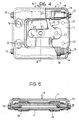
- a motor-vehicle rear suspension is generally indicated 1 and includes a support frame 2. Pivoting longitudinal arms 3 support wheels 4 and are articulated to the support frame 2. Helical springs 6 and shock-absorbers 7 are situated between the pivoting arms and the support frame 2. An anti-roll bar 8 is situated between the longitudinal arms 3.
- the suspension support-frame 2 is fixed to the body of the vehicle by means of four attachment members 5.
- Each attachment member 5 comprises a first element 9 fixed to the body of the vehicle and a second element 10 fixed to the suspension support-frame 2.
- the first element 9 is constituted by a plate 11 in which holes 12 are formed for attachment to the body of the vehicle.
- the plate 11 has a turned-over peripheral edge 13.
- the ends of two guide pins 14 are fixed by means of screws 15 to the two opposite sides of the plate 11.
- the second element 10 of the attachment member 5 is constituted by a plate 16 to whose sides two bushes 17 are fixed.
- the bushes 17 are slidably mounted on the guide pins 14; in order to facilitate sliding, the contact between the bushes 17 and the guide pins 14 is lubricated and protective covers 18 are provided for the sealing of the lubricant.
- the plate 16 constituting the second element 10 is fixed to the suspension support frame 2 by means of a rubber support 19.
- a screw 20 forms the connections between the support frame 2, the rubber support 19 and the plate 16 of the second element 10 and is engaged in a stop element 21.
- the stop element 21 is slidable in a slot 22 formed in the plate 11 of the first element 9 to define the extreme end-of-travel position of the second element 10 relative to the first element 9.
- the plate 16 of the second element 10 has a hole 23 for attachment to a rod 24 of a hydraulic actuator 25.
- Each attachment member 5 is mounted on the suspension support-frame 2 so that the direction in which the second element 10 slides relative to the first element 9 is tangential to a circumference whose centre lies on a vertical axis A contained substantially in the longitudinal median plane of the motor vehicle.
- an hydraulic control unit of the conventional type, or a mechanical type reversing device activates the actuators 25 to effect a travel which is predetermined in dependence on the steering angle of the front wheels.
- the second elements 10 of the attachment members 5 thus move relative to the first elements 9 and steer the rear axle.
Landscapes
- Engineering & Computer Science (AREA)
- Mechanical Engineering (AREA)
- Chemical & Material Sciences (AREA)
- Combustion & Propulsion (AREA)
- Transportation (AREA)
- Vehicle Body Suspensions (AREA)
- Steering-Linkage Mechanisms And Four-Wheel Steering (AREA)
- Arrangement Or Mounting Of Propulsion Units For Vehicles (AREA)
Claims (9)
Applications Claiming Priority (2)
| Application Number | Priority Date | Filing Date | Title |
|---|---|---|---|
| IT67392/88A IT1219248B (it) | 1988-04-27 | 1988-04-27 | Dispositivo per la sterzatura dell'assale posteriore di un autoveicolo |
| IT6739288 | 1988-04-27 |
Publications (2)
| Publication Number | Publication Date |
|---|---|
| EP0340179A1 EP0340179A1 (fr) | 1989-11-02 |
| EP0340179B1 true EP0340179B1 (fr) | 1992-08-12 |
Family
ID=11302011
Family Applications (1)
| Application Number | Title | Priority Date | Filing Date |
|---|---|---|---|
| EP89830156A Expired EP0340179B1 (fr) | 1988-04-27 | 1989-04-11 | Dispositif de direction pour le train arrière d'un véhicule moteur |
Country Status (6)
| Country | Link |
|---|---|
| US (1) | US5005849A (fr) |
| EP (1) | EP0340179B1 (fr) |
| BR (1) | BR8902438A (fr) |
| DE (1) | DE68902416T2 (fr) |
| ES (1) | ES2034756T3 (fr) |
| IT (1) | IT1219248B (fr) |
Families Citing this family (8)
| Publication number | Priority date | Publication date | Assignee | Title |
|---|---|---|---|---|
| IT1239857B (it) * | 1990-01-24 | 1993-11-15 | Fiat Auto Spa | Dispositivo meccanico per la sterzatura delle ruote posteriori di un autoveicolo a quattro ruote sterzanti. |
| FR2657563B1 (fr) * | 1990-01-29 | 1994-06-10 | Peugeot | Essieu arriere de vehicule automobile comportant une traverse montee pivotante par rapport a la caisse et vehicule equipe d'un tel essieu. |
| US5560640A (en) * | 1995-05-22 | 1996-10-01 | Hyundai Motor Company | Rear suspension for a four-wheel steering system |
| DE19623997A1 (de) * | 1996-06-15 | 1997-12-18 | Daimler Benz Ag | Fahrschemel zur Verbindung der Radführungselemente eines Fahrzeuges mit dessen Aufbau |
| EP0816139B1 (fr) * | 1996-06-21 | 2002-09-18 | Volkswagen Aktiengesellschaft | Châssis auxiliaire pour véhicule automobile |
| US6302418B1 (en) * | 2000-04-20 | 2001-10-16 | Meritor Suspensionsystems Company | Modular suspension beam |
| KR100435681B1 (ko) * | 2001-09-11 | 2004-06-12 | 현대자동차주식회사 | 스티어링 기어 프레임을 이용한 최적의 서스펜션 레이아웃 |
| KR20100045800A (ko) * | 2008-10-24 | 2010-05-04 | 현대자동차주식회사 | 서스펜션용 서브 프레임 |
Family Cites Families (10)
| Publication number | Priority date | Publication date | Assignee | Title |
|---|---|---|---|---|
| US661594A (en) * | 1900-03-27 | 1900-11-13 | Thomas J Price | Vehicle. |
| US3669202A (en) * | 1970-10-07 | 1972-06-13 | Adolph Leslie Andersen | Four wheel drive vehicle |
| US4146109A (en) * | 1977-12-29 | 1979-03-27 | Allis-Chalmers Corporation | Chassis suspension system for an articulated vehicle |
| US4286798A (en) * | 1979-05-29 | 1981-09-01 | Butler Claude O | Truck with steerable rear wheels |
| DE3200879A1 (de) * | 1982-01-14 | 1983-03-17 | Daimler-Benz Ag, 7000 Stuttgart | "vorrichtung zur einstellung der schwenkachse eines gelenks zur schwenkfaehigen aufhaengung eines fuehrungslenkers zur fuehrung eines rades, insbesondere eines fahrzeughinterrades" |
| JPS58214469A (ja) * | 1982-06-07 | 1983-12-13 | Nissan Motor Co Ltd | 後輪操舵装置 |
| DE3524763C2 (de) * | 1984-07-30 | 1994-04-21 | Volkswagen Ag | Kraftfahrzeug-Hinterachse, insbesondere für Personenkraftwagen |
| JPS6255204A (ja) * | 1985-09-03 | 1987-03-10 | Toyota Motor Corp | ト−イン調整装置 |
| FR2601297B1 (fr) * | 1986-07-10 | 1990-05-25 | Peugeot | Train arriere pour vehicule automobile a action passive et vehicule automobile d'un tel train. |
| DE3627422A1 (de) * | 1986-08-13 | 1988-02-18 | Bayerische Motoren Werke Ag | Lagerbock fuer einen lenker eines kraftfahrzeugs |
-
1988
- 1988-04-27 IT IT67392/88A patent/IT1219248B/it active
-
1989
- 1989-04-11 DE DE8989830156T patent/DE68902416T2/de not_active Expired - Fee Related
- 1989-04-11 ES ES198989830156T patent/ES2034756T3/es not_active Expired - Lifetime
- 1989-04-11 EP EP89830156A patent/EP0340179B1/fr not_active Expired
- 1989-04-21 US US07/341,603 patent/US5005849A/en not_active Expired - Fee Related
- 1989-04-25 BR BR898902438A patent/BR8902438A/pt not_active IP Right Cessation
Also Published As
| Publication number | Publication date |
|---|---|
| ES2034756T3 (es) | 1993-04-01 |
| DE68902416D1 (de) | 1992-09-17 |
| US5005849A (en) | 1991-04-09 |
| BR8902438A (pt) | 1990-03-01 |
| DE68902416T2 (de) | 1993-01-07 |
| EP0340179A1 (fr) | 1989-11-02 |
| IT8867392A0 (it) | 1988-04-27 |
| IT1219248B (it) | 1990-05-03 |
Similar Documents
| Publication | Publication Date | Title |
|---|---|---|
| US5186486A (en) | Active link for a stabilizer bar | |
| US4722544A (en) | Mounting assembly for unsteerable wheels | |
| US5288091A (en) | Four wheel steering apparatus | |
| US3893701A (en) | Wheel suspension for vehicles with an elastic toe-in change | |
| US4754992A (en) | Independent rear suspension for use of motor vehicles | |
| US4610461A (en) | Steering system for elimination of bump steering in independent wheel suspension systems | |
| GB2039258A (en) | Motor vehicle rear suspension systems | |
| US5249817A (en) | Motor vehicle front steerable axis with torsion bar stabilizer | |
| EP0340179B1 (fr) | Dispositif de direction pour le train arrière d'un véhicule moteur | |
| US4556235A (en) | Independent wheel suspension for non-steered wheels of motor vehicles | |
| DE2200351B1 (de) | ? Radaufhaengung fuer Kraftfahrzeuge | |
| US4324416A (en) | Wheel suspension for motor vehicles | |
| EP0454993B1 (fr) | Suspension de véhicule | |
| EP0454994B1 (fr) | Suspension de véhicule | |
| DE69109830T2 (de) | Aufhängungsvorrichtung, insbesondere für gelenktes Rad eines Kraftfahrzeugs. | |
| DE1957145B2 (de) | Einzelradaufhängung für die Hinterräder an Kraftfahrzeugen | |
| GB2048795A (en) | Rear axle for motor vehicles | |
| US4842295A (en) | Vehicle wheel suspension | |
| DE4444115C2 (de) | Mehrspuriges Leichtfahrzeug | |
| EP0785124B1 (fr) | Mécanisme de direction mixte | |
| US5511817A (en) | Vehicle axle suspension system | |
| US4211311A (en) | Railway car truck and brake support structure | |
| US4655474A (en) | Independent vehicle wheel suspension | |
| US4695069A (en) | Steering system for rear wheels | |
| JP2817345B2 (ja) | キャンバー角制御装置 |
Legal Events
| Date | Code | Title | Description |
|---|---|---|---|
| PUAI | Public reference made under article 153(3) epc to a published international application that has entered the european phase |
Free format text: ORIGINAL CODE: 0009012 |
|
| AK | Designated contracting states |
Kind code of ref document: A1 Designated state(s): DE ES FR GB SE |
|
| 17P | Request for examination filed |
Effective date: 19900203 |
|
| 17Q | First examination report despatched |
Effective date: 19910607 |
|
| GRAA | (expected) grant |
Free format text: ORIGINAL CODE: 0009210 |
|
| AK | Designated contracting states |
Kind code of ref document: B1 Designated state(s): DE ES FR GB SE |
|
| REF | Corresponds to: |
Ref document number: 68902416 Country of ref document: DE Date of ref document: 19920917 |
|
| ET | Fr: translation filed | ||
| REG | Reference to a national code |
Ref country code: ES Ref legal event code: FG2A Ref document number: 2034756 Country of ref document: ES Kind code of ref document: T3 |
|
| PLBE | No opposition filed within time limit |
Free format text: ORIGINAL CODE: 0009261 |
|
| STAA | Information on the status of an ep patent application or granted ep patent |
Free format text: STATUS: NO OPPOSITION FILED WITHIN TIME LIMIT |
|
| 26N | No opposition filed | ||
| EAL | Se: european patent in force in sweden |
Ref document number: 89830156.9 |
|
| PGFP | Annual fee paid to national office [announced via postgrant information from national office to epo] |
Ref country code: SE Payment date: 19960314 Year of fee payment: 8 |
|
| PGFP | Annual fee paid to national office [announced via postgrant information from national office to epo] |
Ref country code: GB Payment date: 19960319 Year of fee payment: 8 |
|
| PGFP | Annual fee paid to national office [announced via postgrant information from national office to epo] |
Ref country code: ES Payment date: 19960418 Year of fee payment: 8 |
|
| PG25 | Lapsed in a contracting state [announced via postgrant information from national office to epo] |
Ref country code: GB Effective date: 19970411 |
|
| PG25 | Lapsed in a contracting state [announced via postgrant information from national office to epo] |
Ref country code: SE Effective date: 19970412 Ref country code: ES Free format text: LAPSE BECAUSE OF NON-PAYMENT OF DUE FEES Effective date: 19970412 |
|
| GBPC | Gb: european patent ceased through non-payment of renewal fee |
Effective date: 19970411 |
|
| EUG | Se: european patent has lapsed |
Ref document number: 89830156.9 |
|
| PGFP | Annual fee paid to national office [announced via postgrant information from national office to epo] |
Ref country code: DE Payment date: 19980325 Year of fee payment: 10 |
|
| PGFP | Annual fee paid to national office [announced via postgrant information from national office to epo] |
Ref country code: FR Payment date: 19980430 Year of fee payment: 10 |
|
| REG | Reference to a national code |
Ref country code: ES Ref legal event code: FD2A Effective date: 19990405 |
|
| PG25 | Lapsed in a contracting state [announced via postgrant information from national office to epo] |
Ref country code: FR Free format text: LAPSE BECAUSE OF NON-PAYMENT OF DUE FEES Effective date: 19991231 |
|
| REG | Reference to a national code |
Ref country code: FR Ref legal event code: ST |
|
| PG25 | Lapsed in a contracting state [announced via postgrant information from national office to epo] |
Ref country code: DE Free format text: LAPSE BECAUSE OF NON-PAYMENT OF DUE FEES Effective date: 20000201 |