EP0339380B1 - Vorrichtung zur koaxialen drehfesten Verbindung zweier Teile - Google Patents
Vorrichtung zur koaxialen drehfesten Verbindung zweier Teile Download PDFInfo
- Publication number
- EP0339380B1 EP0339380B1 EP89106589A EP89106589A EP0339380B1 EP 0339380 B1 EP0339380 B1 EP 0339380B1 EP 89106589 A EP89106589 A EP 89106589A EP 89106589 A EP89106589 A EP 89106589A EP 0339380 B1 EP0339380 B1 EP 0339380B1
- Authority
- EP
- European Patent Office
- Prior art keywords
- pinion
- driving shaft
- outer cylinder
- extension
- cylinder wall
- Prior art date
- Legal status (The legal status is an assumption and is not a legal conclusion. Google has not performed a legal analysis and makes no representation as to the accuracy of the status listed.)
- Expired - Lifetime
Links
Images
Classifications
-
- F—MECHANICAL ENGINEERING; LIGHTING; HEATING; WEAPONS; BLASTING
- F16—ENGINEERING ELEMENTS AND UNITS; GENERAL MEASURES FOR PRODUCING AND MAINTAINING EFFECTIVE FUNCTIONING OF MACHINES OR INSTALLATIONS; THERMAL INSULATION IN GENERAL
- F16D—COUPLINGS FOR TRANSMITTING ROTATION; CLUTCHES; BRAKES
- F16D1/00—Couplings for rigidly connecting two coaxial shafts or other movable machine elements
- F16D1/02—Couplings for rigidly connecting two coaxial shafts or other movable machine elements for connecting two abutting shafts or the like
-
- F—MECHANICAL ENGINEERING; LIGHTING; HEATING; WEAPONS; BLASTING
- F16—ENGINEERING ELEMENTS AND UNITS; GENERAL MEASURES FOR PRODUCING AND MAINTAINING EFFECTIVE FUNCTIONING OF MACHINES OR INSTALLATIONS; THERMAL INSULATION IN GENERAL
- F16D—COUPLINGS FOR TRANSMITTING ROTATION; CLUTCHES; BRAKES
- F16D1/00—Couplings for rigidly connecting two coaxial shafts or other movable machine elements
- F16D1/10—Quick-acting couplings in which the parts are connected by simply bringing them together axially
- F16D1/108—Quick-acting couplings in which the parts are connected by simply bringing them together axially having retaining means rotating with the coupling and acting by interengaging parts, i.e. positive coupling
- F16D1/116—Quick-acting couplings in which the parts are connected by simply bringing them together axially having retaining means rotating with the coupling and acting by interengaging parts, i.e. positive coupling the interengaging parts including a continuous or interrupted circumferential groove in the surface of one of the coupling parts
Definitions
- the invention relates to a device for the coaxial, rotationally fixed, axially fixable connection of a pinion with a drive shaft of a motor via an engaging external and internal toothing and superimposed cylinder surfaces of a pinion extension and the drive shaft, with a cross pin.
- the two parts to be connected to one another can be a shaft, such as a motor shaft, and in particular as a second part a pinion. So far, the corresponding parts have generally been secured by key connections or non-positively against rotation. There was either a certain amount of play, or no positive locking was guaranteed.
- US-A-2 587 838 describes a PTO adapter for the PTO of a tractor.
- the shaft-like adapter is connected to the PTO shaft by means of an engaging external or internal toothing.
- a dowel pin is provided for axial fixing, which is penetrated through the entire cross section.
- GB-A-2 019 528 describes a shaft coupling which serves as a quick change part for use in a slow running rolling device.
- the two coupling parts 6 and 8 are not axially fixed to one another.
- EP-A1-0 088 589 describes a connection device for driving a viscosity coupling. However, neither external nor internal toothing is provided for the transmission of torques.
- FR-A-2 279 972 describes a coupling device for two hollow shafts to be coupled.
- a central screw is used for axial locking.
- Such a configuration does not make sense for a pinion attachment, since on the one hand the pinion cross section would be weakened and on the other hand such a pinion would be very difficult to replace.
- US-A-3 847 248 describes a lubrication device for a driver connection between a pinion and a shaft.
- the driver connection is realized by split pins or feather keys. Such connections are unsuitable for changing torque loads due to the relative movement that occurs between the shaft and pinion.
- the pinion is by lying on top of each other Cylinder surfaces are guided coaxially to the shaft and secured against axial displacement by a snap ring.
- GB-A-1 205 199 describes a locking device for high speed shafts.
- a hollow pinion is described, which is provided with internal teeth on a correspondingly adapted shaft with external teeth.
- the coaxial guide is served by a hollow cylindrical surface of the hollow pinion, which rests on a corresponding outer cylindrical surface of the shaft, and a second hollow cylindrical surface, which rests on an outer cylindrical surface of a securing part (FIG. 1).
- DE-C-3 712 195 describes a device for fine adjustment of the angular position of a shaft to a component detachably connected to it on the same axis.
- This device is intended in particular for adjusting the angular position of a steering wheel hub relative to a steering shaft.
- a bushing with external and internal teeth is arranged between the steering shaft and steering wheel hub.
- the shaft has external teeth and the steering wheel hub has internal teeth.
- the steering wheel hub is centered via an inner cylinder surface and an inclined surface.
- DE-A-3 711 163 describes a device for releasably tightening disk-shaped or ring-shaped rollers.
- a rotationally fixed connection between a roller and a shaft is realized by frictional engagement by means of a prestressed bush.
- FR-A-1 304 987 describes a shaft with external teeth and another part with an adapted internal teeth.
- the teeth are designed so that there is coaxial guidance of the part with respect to the shaft. In this case, an axial fixing takes place only in one direction.
- the invention has for its object to provide a device for releasably connecting a pinion to a drive shaft, which enables good centering and play-free, positive connection of both parts in a simple manner.
- the stated object is achieved in a device of the type mentioned in the introduction in that the pinion extension has two outer cylinder walls and an external toothing arranged between them, in that the outer cylinder wall of the pinion extension closest to the pinion has a larger diameter than the other outer cylinder wall in that the drive shaft is free End for receiving the shaft extension is provided with an axial blind bore, which is designed with two hollow cylinder sections adapted to the outer cylinder walls and an internal toothing in between, so that when the shaft extension is inserted, the inner and outer toothings come into engagement and the hollow cylinder sections arranged on both sides and corresponding outer cylinder walls provide the coaxial Guide the pinion with respect to the drive shaft ensure that the cross pin is a cross grub screw that is screwed into the drive shaft t is and has a conical or frustoconical tip that the outer cylinder wall of the pinion extension, which is more distant from the pinion, has an annular groove with a cross section adapted to the tip for receiving the cross-threaded pin
- the configuration according to the invention separates the centering of the two parts to be connected to one another via the cylinder walls from the torque entrainment via the toothing designs. Good centering is achieved in this way and torque-free play is possible.
- the toothing designs can be designed in a variety of ways, as many-part profiles, as involute teeth, cycloid teeth, polygon profiles or the like.
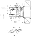
- the device 1 serves for the rotationally fixed connection of two mutually rotatable parts 2, 3, such as in particular a shaft 2, such as a motor shaft, and a pinion 3 as a second part.
- the first part 2 has an axial starting from its free end face 4 Blind bore 5, which, starting from the end face 4, is initially formed by a cylinder wall 6, which is followed by an internal toothing 7, the groove diameter of which is at most as large as the diameter of the cylinder wall 6.
- the internal toothing 7 is followed by another Inner cylinder wall 8, the diameter of which is at most as large as the diameter of the tooth tips of the toothing 7.
- a lug 9 of the second part 3 is inserted into the bore 5, which has a configuration complementary to the described configuration of the bore 5 and accordingly has an outer cylinder wall 10 with a diameter corresponding to the inner cylinder wall 6.
- This section is followed by an external toothing 11 which is complementary to the internal toothing 7.
- the shoulder 9 of the second part 3 is provided with an annular groove 13.
- the first part 1 has at least one transverse threaded bore 15, into which a grub screw 14 is screwed with an inner end 16 adapted to the annular groove 13, the end 16 of which is connected to the groove 13 of the Approach 9 attacks.
- the second part 3 is axially fixed by pulling it with an end face 17 facing the part 1 against the end face 4 of the part 2.
- the centering of the two parts 2, 3 relative to one another takes place via the cylinder wall surfaces 6, 10 and 8, 12, while the torque is carried over the toothings 7, 11. Torque entrainment and centering are therefore separated from one another in the device according to the invention.
- part 2 is a Motor shaft is to sit on a centrifugal disc or spray disc 18 to prevent an oil jet emerging from, for example, meshing teeth from reaching the shaft sealing ring 19.
- a bearing of the motor shaft 2 is designated 20.
Landscapes
- General Engineering & Computer Science (AREA)
- Engineering & Computer Science (AREA)
- Mechanical Engineering (AREA)
- Coupling Device And Connection With Printed Circuit (AREA)
- Magnetic Resonance Imaging Apparatus (AREA)
- Arrangement And Driving Of Transmission Devices (AREA)
- Apparatus For Radiation Diagnosis (AREA)
- Mechanical Operated Clutches (AREA)
- Details Of Connecting Devices For Male And Female Coupling (AREA)
- Gears, Cams (AREA)
- Non-Reversible Transmitting Devices (AREA)
- Mutual Connection Of Rods And Tubes (AREA)
- Channel Selection Circuits, Automatic Tuning Circuits (AREA)
- Television Receiver Circuits (AREA)
- Devices For Indicating Variable Information By Combining Individual Elements (AREA)
- Waveguide Connection Structure (AREA)
- Measurement Of Velocity Or Position Using Acoustic Or Ultrasonic Waves (AREA)
- Endoscopes (AREA)
- Turbine Rotor Nozzle Sealing (AREA)
Priority Applications (1)
| Application Number | Priority Date | Filing Date | Title |
|---|---|---|---|
| AT89106589T ATE82621T1 (de) | 1988-04-28 | 1989-04-13 | Vorrichtung zur koaxialen drehfesten verbindung zweier teile. |
Applications Claiming Priority (2)
| Application Number | Priority Date | Filing Date | Title |
|---|---|---|---|
| DE8805632U | 1988-04-28 | ||
| DE8805632U DE8805632U1 (de) | 1988-04-28 | 1988-04-28 | Vorrichtung zur koaxialen drehfesten Verbindung zweier Teile |
Publications (2)
| Publication Number | Publication Date |
|---|---|
| EP0339380A1 EP0339380A1 (de) | 1989-11-02 |
| EP0339380B1 true EP0339380B1 (de) | 1992-11-19 |
Family
ID=6823480
Family Applications (1)
| Application Number | Title | Priority Date | Filing Date |
|---|---|---|---|
| EP89106589A Expired - Lifetime EP0339380B1 (de) | 1988-04-28 | 1989-04-13 | Vorrichtung zur koaxialen drehfesten Verbindung zweier Teile |
Country Status (7)
| Country | Link |
|---|---|
| EP (1) | EP0339380B1 (da) |
| AT (1) | ATE82621T1 (da) |
| DE (2) | DE8805632U1 (da) |
| DK (1) | DK203889A (da) |
| FI (1) | FI891826A7 (da) |
| NO (1) | NO171327C (da) |
| PT (1) | PT90385A (da) |
Cited By (7)
| Publication number | Priority date | Publication date | Assignee | Title |
|---|---|---|---|---|
| DE10137025C1 (de) * | 2001-07-30 | 2002-12-05 | Sew Eurodrive Gmbh & Co | Baureihe von Wellen und Verfahren zur Fertigung |
| WO2003100278A1 (de) | 2002-05-24 | 2003-12-04 | Sew-Eurodrive Gmbh & Co | Baureihe von wellen und verfahren zur fertigung |
| DE10302072B3 (de) * | 2002-12-20 | 2004-09-09 | Sew-Eurodrive Gmbh & Co Kg | Welle, Getriebemotor, Verfahren zum Wiedermontieren einer Verbindung, Baureihe von Wellen und Verfahren zur Fertigung |
| DE102005059018B4 (de) * | 2005-12-08 | 2008-06-12 | Sew-Eurodrive Gmbh & Co. Kg | Elektromotor und Verbindung zwischen einer Rotorwelle und einem Rotorblechpaket |
| DE102008040321A1 (de) * | 2008-07-10 | 2010-01-14 | Sumitomo (Shi) Cyclo Drive Germany Gmbh | Ritzelbefestigung für Planetengetriebe |
| DE102015109101A1 (de) * | 2015-06-09 | 2016-12-15 | Ebm-Papst St. Georgen Gmbh & Co. Kg | Antriebsvorrichtung und Verfahren zur Montage einer Antriebsvorrichtung |
| DE102021201766A1 (de) | 2021-02-25 | 2022-08-25 | Zf Friedrichshafen Ag | Passverzahnung mit Ölfangnut |
Families Citing this family (12)
| Publication number | Priority date | Publication date | Assignee | Title |
|---|---|---|---|---|
| DE4106096C1 (da) * | 1991-02-27 | 1992-10-15 | Jean Walterscheid Gmbh, 5204 Lohmar, De | |
| DE4419372C2 (de) * | 1994-06-03 | 1998-01-29 | Loehr & Bromkamp Gmbh | Vorrichtung zur Verbindung einer Rohrwelle mit einem Zapfen |
| DE29501158U1 (de) * | 1995-01-25 | 1995-03-30 | Aktiebolaget Electrolux Corporate Patents & Trademarks, Stockholm | Arretiervorrichtung für eine Antriebswelle |
| FR2753753B1 (fr) * | 1996-09-24 | 1999-01-08 | Systeme pour bloquer mecaniquement de maniere demontable un manchon sur un arbre d'entrainement | |
| DE29808420U1 (de) | 1998-05-05 | 1998-07-30 | Petri Ag, 63743 Aschaffenburg | Vorrichtung zur Befestigung einer Nabe auf einer Welle, insbesondere einer Lenkradnabe auf einer Lenksäule |
| DE19836259C2 (de) * | 1998-08-11 | 2001-02-01 | Christoph Puls | Drehfeste Welle-Nabe-Verbindung |
| DE19848324B4 (de) * | 1998-10-20 | 2007-03-22 | Sew-Eurodrive Gmbh & Co. Kg | Kupplung |
| US6883604B2 (en) * | 2001-06-05 | 2005-04-26 | Baker Hughes Incorporated | Shaft locking couplings for submersible pump assemblies |
| DE20120115U1 (de) | 2001-12-12 | 2002-04-18 | Lemke, Norbert, 82178 Puchheim | Befestigungsvorrichtung zur drehbar festen Anbringung eines Radkörpers an eine Achse |
| DE102010047008A1 (de) | 2010-09-30 | 2012-04-05 | Ims Gear Gmbh | Verbindungsstruktur zur mechanischen Verbindung eines ersten Gehäuses mit einem zweiten Gehäuse |
| DE102012012293B4 (de) | 2012-06-20 | 2017-10-26 | Sms Group Gmbh | Vorrichtung zum Umformen eines Werkstücks |
| CN107319920A (zh) * | 2017-08-14 | 2017-11-07 | 王晓杰 | 一种小型即食面条制售机 |
Family Cites Families (9)
| Publication number | Priority date | Publication date | Assignee | Title |
|---|---|---|---|---|
| US2587838A (en) * | 1950-09-20 | 1952-03-04 | Hub City Iron Company | Spline adapter coupler |
| FR1304987A (fr) * | 1961-11-03 | 1962-09-28 | Ministerul Metalurgiei Si Cons | Assemblage rigide par des cannelures à flancs en développante |
| NL6910542A (da) * | 1968-07-11 | 1970-01-13 | ||
| US3847248A (en) * | 1973-08-23 | 1974-11-12 | Caterpillar Tractor Co | Replaceable lubricating cartridge for spline connections |
| DE2436270A1 (de) * | 1974-07-27 | 1976-02-05 | Motoren Turbinen Union | Wellenverbindung |
| GB2019528B (en) * | 1978-04-21 | 1982-07-14 | Davy Loewy Ltd | Shaft couplings |
| EP0088589A1 (en) * | 1982-03-10 | 1983-09-14 | Eaton Corporation | Mounting shaft and adaptor for viscous coupling |
| DE3711163A1 (de) * | 1987-04-02 | 1988-10-20 | Kocks Technik | Vorrichtung zum loesbaren festspannen von scheiben- oder ringfoermigen walzen |
| DE3712195C1 (de) * | 1987-04-10 | 1988-07-07 | Daimler Benz Ag | Vorrichtung zur Feineinstellung der Drehwinkellage einer Welle zu einem mit dieser gleichachsig Ioesbar verbundenen Bauteil |
-
1988
- 1988-04-28 DE DE8805632U patent/DE8805632U1/de not_active Expired
-
1989
- 1989-04-13 EP EP89106589A patent/EP0339380B1/de not_active Expired - Lifetime
- 1989-04-13 AT AT89106589T patent/ATE82621T1/de not_active IP Right Cessation
- 1989-04-13 DE DE8989106589T patent/DE58902738D1/de not_active Expired - Lifetime
- 1989-04-17 FI FI891826A patent/FI891826A7/fi not_active IP Right Cessation
- 1989-04-26 NO NO891739A patent/NO171327C/no unknown
- 1989-04-27 DK DK203889A patent/DK203889A/da not_active Application Discontinuation
- 1989-04-27 PT PT90385A patent/PT90385A/pt not_active Application Discontinuation
Cited By (9)
| Publication number | Priority date | Publication date | Assignee | Title |
|---|---|---|---|---|
| DE10137025C1 (de) * | 2001-07-30 | 2002-12-05 | Sew Eurodrive Gmbh & Co | Baureihe von Wellen und Verfahren zur Fertigung |
| WO2003100278A1 (de) | 2002-05-24 | 2003-12-04 | Sew-Eurodrive Gmbh & Co | Baureihe von wellen und verfahren zur fertigung |
| DE10316155B4 (de) * | 2002-05-24 | 2006-04-20 | Sew-Eurodrive Gmbh & Co. Kg | Welle, Baureihe von Wellen und Verfahren zur Fertigung |
| DE10302072B3 (de) * | 2002-12-20 | 2004-09-09 | Sew-Eurodrive Gmbh & Co Kg | Welle, Getriebemotor, Verfahren zum Wiedermontieren einer Verbindung, Baureihe von Wellen und Verfahren zur Fertigung |
| DE102005059018B4 (de) * | 2005-12-08 | 2008-06-12 | Sew-Eurodrive Gmbh & Co. Kg | Elektromotor und Verbindung zwischen einer Rotorwelle und einem Rotorblechpaket |
| DE102008040321A1 (de) * | 2008-07-10 | 2010-01-14 | Sumitomo (Shi) Cyclo Drive Germany Gmbh | Ritzelbefestigung für Planetengetriebe |
| DE102008040321B4 (de) * | 2008-07-10 | 2010-12-02 | Sumitomo (Shi) Cyclo Drive Germany Gmbh | Ritzelbefestigung für Planetengetriebe |
| DE102015109101A1 (de) * | 2015-06-09 | 2016-12-15 | Ebm-Papst St. Georgen Gmbh & Co. Kg | Antriebsvorrichtung und Verfahren zur Montage einer Antriebsvorrichtung |
| DE102021201766A1 (de) | 2021-02-25 | 2022-08-25 | Zf Friedrichshafen Ag | Passverzahnung mit Ölfangnut |
Also Published As
| Publication number | Publication date |
|---|---|
| FI891826A0 (fi) | 1989-04-17 |
| FI891826L (fi) | 1989-10-29 |
| ATE82621T1 (de) | 1992-12-15 |
| NO891739D0 (no) | 1989-04-26 |
| DK203889A (da) | 1989-10-29 |
| EP0339380A1 (de) | 1989-11-02 |
| FI891826A7 (fi) | 1989-10-29 |
| NO171327B (no) | 1992-11-16 |
| DE58902738D1 (de) | 1992-12-24 |
| DE8805632U1 (de) | 1988-06-09 |
| DK203889D0 (da) | 1989-04-27 |
| NO891739L (no) | 1989-10-30 |
| NO171327C (no) | 1993-02-24 |
| PT90385A (pt) | 1989-11-10 |
Similar Documents
| Publication | Publication Date | Title |
|---|---|---|
| EP0339380B1 (de) | Vorrichtung zur koaxialen drehfesten Verbindung zweier Teile | |
| EP0747606B1 (de) | Verschluss zur Sicherung einer Kupplungshülse | |
| EP2142386B1 (de) | Lageranordnung einer über ein drehgelenk antreibbaren radnabe eines kraftfahrzeuges | |
| DE3246233C2 (da) | ||
| WO2008148373A1 (de) | Vorrichtung zur drehfesten verbindung eines zapfens eines getriebes mit einem gelenkkörper eines antriebsgelenks einer antriebswelle | |
| DE19648998B4 (de) | Anordnung, die bei Teleskopwellen anwendbar ist | |
| DE3626851A1 (de) | Befestigungsvorrichtung fuer rotative schleifwerkzeuge, insbesondere schleifscheiben, auf einer spindel | |
| DE10258515A1 (de) | Planetengetriebe | |
| DE2348731C2 (de) | Kantenbearbeitungswerkzeug | |
| EP4680870A1 (de) | Getriebemotor | |
| EP0790423A1 (de) | Verfahren zur Herstellung einer Vorrichtung zum Verbinden eines kerbverzahnten, der Übertragung von Drehmomenten dienenden Wellenzapfens | |
| DE3835544C1 (da) | ||
| EP1360424B1 (de) | Flanschmitnehmer für kreuzgelenke | |
| EP0480159A1 (de) | Vorrichtung zur Erzeugung eines überlagerten Lenkkorrektureingriffs | |
| DE3916315A1 (de) | Schaftwerkzeug | |
| DE2940762C2 (de) | Vorspannbare Doppelmutter für Kugelgewindespindeln | |
| DE3806259C1 (da) | ||
| EP0062109A1 (de) | Lösbare Verbindung zur Übertragung hoher Drehmomente | |
| EP0489007A1 (de) | Drehfeste flanschverbindung | |
| EP1003650A1 (de) | Vorderachsabtrieb eines automatgetriebes | |
| EP0126284B1 (de) | Hobelmaschine, insbesondere Handhobel | |
| EP0877173A1 (de) | Kraftübertragungswelle aus faserverstärktem Kunststoff | |
| DE2335097A1 (de) | Kupplung | |
| EP0644347B1 (de) | Ausgleichskupplung | |
| DE4140427C1 (en) | Inner toothed component on shaft multi-wedge profile - has ring, associated with shaft side annular shoulder, fitted with deformation ring, with second ring forming elastic support |
Legal Events
| Date | Code | Title | Description |
|---|---|---|---|
| PUAI | Public reference made under article 153(3) epc to a published international application that has entered the european phase |
Free format text: ORIGINAL CODE: 0009012 |
|
| AK | Designated contracting states |
Kind code of ref document: A1 Designated state(s): AT BE CH DE ES FR GB GR IT LI LU NL SE |
|
| 17P | Request for examination filed |
Effective date: 19900428 |
|
| 17Q | First examination report despatched |
Effective date: 19910718 |
|
| GRAA | (expected) grant |
Free format text: ORIGINAL CODE: 0009210 |
|
| AK | Designated contracting states |
Kind code of ref document: B1 Designated state(s): AT BE CH DE ES FR GB GR IT LI LU NL SE |
|
| PG25 | Lapsed in a contracting state [announced via postgrant information from national office to epo] |
Ref country code: GR Free format text: LAPSE BECAUSE OF FAILURE TO SUBMIT A TRANSLATION OF THE DESCRIPTION OR TO PAY THE FEE WITHIN THE PRESCRIBED TIME-LIMIT Effective date: 19921119 Ref country code: NL Effective date: 19921119 Ref country code: BE Effective date: 19921119 Ref country code: GB Effective date: 19921119 Ref country code: FR Effective date: 19921119 Ref country code: SE Effective date: 19921119 Ref country code: ES Free format text: THE PATENT HAS BEEN ANNULLED BY A DECISION OF A NATIONAL AUTHORITY Effective date: 19921119 Ref country code: IT Free format text: LAPSE BECAUSE OF FAILURE TO SUBMIT A TRANSLATION OF THE DESCRIPTION OR TO PAY THE FEE WITHIN THE PRE;WARNING: LAPSES OF ITALIAN PATENTS WITH EFFECTIVE DATE BEFORE 2007 MAY HAVE OCCURRED AT ANY TIME BEFORE 2007. THE CORRECT EFFECTIVE DATE MAY BE DIFFERENT FROM THE ONE RECORDED.SCRIBED TIME-LIMIT Effective date: 19921119 |
|
| REF | Corresponds to: |
Ref document number: 82621 Country of ref document: AT Date of ref document: 19921215 Kind code of ref document: T |
|
| REF | Corresponds to: |
Ref document number: 58902738 Country of ref document: DE Date of ref document: 19921224 |
|
| EN | Fr: translation not filed | ||
| PG25 | Lapsed in a contracting state [announced via postgrant information from national office to epo] |
Ref country code: AT Effective date: 19930413 |
|
| NLV1 | Nl: lapsed or annulled due to failure to fulfill the requirements of art. 29p and 29m of the patents act | ||
| PG25 | Lapsed in a contracting state [announced via postgrant information from national office to epo] |
Ref country code: LI Effective date: 19930430 Ref country code: LU Free format text: LAPSE BECAUSE OF NON-PAYMENT OF DUE FEES Effective date: 19930430 Ref country code: CH Effective date: 19930430 |
|
| GBV | Gb: ep patent (uk) treated as always having been void in accordance with gb section 77(7)/1977 [no translation filed] |
Effective date: 19921119 |
|
| PLBE | No opposition filed within time limit |
Free format text: ORIGINAL CODE: 0009261 |
|
| STAA | Information on the status of an ep patent application or granted ep patent |
Free format text: STATUS: NO OPPOSITION FILED WITHIN TIME LIMIT |
|
| 26N | No opposition filed | ||
| REG | Reference to a national code |
Ref country code: CH Ref legal event code: PL |
|
| PGFP | Annual fee paid to national office [announced via postgrant information from national office to epo] |
Ref country code: DE Payment date: 20080626 Year of fee payment: 20 |