EP0339380B1 - Device for connecting two machine parts to rotate together and about the same axis - Google Patents
Device for connecting two machine parts to rotate together and about the same axis Download PDFInfo
- Publication number
- EP0339380B1 EP0339380B1 EP89106589A EP89106589A EP0339380B1 EP 0339380 B1 EP0339380 B1 EP 0339380B1 EP 89106589 A EP89106589 A EP 89106589A EP 89106589 A EP89106589 A EP 89106589A EP 0339380 B1 EP0339380 B1 EP 0339380B1
- Authority
- EP
- European Patent Office
- Prior art keywords
- pinion
- driving shaft
- outer cylinder
- extension
- cylinder wall
- Prior art date
- Legal status (The legal status is an assumption and is not a legal conclusion. Google has not performed a legal analysis and makes no representation as to the accuracy of the status listed.)
- Expired - Lifetime
Links
Images
Classifications
-
- F—MECHANICAL ENGINEERING; LIGHTING; HEATING; WEAPONS; BLASTING
- F16—ENGINEERING ELEMENTS AND UNITS; GENERAL MEASURES FOR PRODUCING AND MAINTAINING EFFECTIVE FUNCTIONING OF MACHINES OR INSTALLATIONS; THERMAL INSULATION IN GENERAL
- F16D—COUPLINGS FOR TRANSMITTING ROTATION; CLUTCHES; BRAKES
- F16D1/00—Couplings for rigidly connecting two coaxial shafts or other movable machine elements
- F16D1/02—Couplings for rigidly connecting two coaxial shafts or other movable machine elements for connecting two abutting shafts or the like
-
- F—MECHANICAL ENGINEERING; LIGHTING; HEATING; WEAPONS; BLASTING
- F16—ENGINEERING ELEMENTS AND UNITS; GENERAL MEASURES FOR PRODUCING AND MAINTAINING EFFECTIVE FUNCTIONING OF MACHINES OR INSTALLATIONS; THERMAL INSULATION IN GENERAL
- F16D—COUPLINGS FOR TRANSMITTING ROTATION; CLUTCHES; BRAKES
- F16D1/00—Couplings for rigidly connecting two coaxial shafts or other movable machine elements
- F16D1/10—Quick-acting couplings in which the parts are connected by simply bringing them together axially
- F16D1/108—Quick-acting couplings in which the parts are connected by simply bringing them together axially having retaining means rotating with the coupling and acting by interengaging parts, i.e. positive coupling
- F16D1/116—Quick-acting couplings in which the parts are connected by simply bringing them together axially having retaining means rotating with the coupling and acting by interengaging parts, i.e. positive coupling the interengaging parts including a continuous or interrupted circumferential groove in the surface of one of the coupling parts
Definitions
- the invention relates to a device for the coaxial, rotationally fixed, axially fixable connection of a pinion with a drive shaft of a motor via an engaging external and internal toothing and superimposed cylinder surfaces of a pinion extension and the drive shaft, with a cross pin.
- the two parts to be connected to one another can be a shaft, such as a motor shaft, and in particular as a second part a pinion. So far, the corresponding parts have generally been secured by key connections or non-positively against rotation. There was either a certain amount of play, or no positive locking was guaranteed.
- US-A-2 587 838 describes a PTO adapter for the PTO of a tractor.
- the shaft-like adapter is connected to the PTO shaft by means of an engaging external or internal toothing.
- a dowel pin is provided for axial fixing, which is penetrated through the entire cross section.
- GB-A-2 019 528 describes a shaft coupling which serves as a quick change part for use in a slow running rolling device.
- the two coupling parts 6 and 8 are not axially fixed to one another.
- EP-A1-0 088 589 describes a connection device for driving a viscosity coupling. However, neither external nor internal toothing is provided for the transmission of torques.
- FR-A-2 279 972 describes a coupling device for two hollow shafts to be coupled.
- a central screw is used for axial locking.
- Such a configuration does not make sense for a pinion attachment, since on the one hand the pinion cross section would be weakened and on the other hand such a pinion would be very difficult to replace.
- US-A-3 847 248 describes a lubrication device for a driver connection between a pinion and a shaft.
- the driver connection is realized by split pins or feather keys. Such connections are unsuitable for changing torque loads due to the relative movement that occurs between the shaft and pinion.
- the pinion is by lying on top of each other Cylinder surfaces are guided coaxially to the shaft and secured against axial displacement by a snap ring.
- GB-A-1 205 199 describes a locking device for high speed shafts.
- a hollow pinion is described, which is provided with internal teeth on a correspondingly adapted shaft with external teeth.
- the coaxial guide is served by a hollow cylindrical surface of the hollow pinion, which rests on a corresponding outer cylindrical surface of the shaft, and a second hollow cylindrical surface, which rests on an outer cylindrical surface of a securing part (FIG. 1).
- DE-C-3 712 195 describes a device for fine adjustment of the angular position of a shaft to a component detachably connected to it on the same axis.
- This device is intended in particular for adjusting the angular position of a steering wheel hub relative to a steering shaft.
- a bushing with external and internal teeth is arranged between the steering shaft and steering wheel hub.
- the shaft has external teeth and the steering wheel hub has internal teeth.
- the steering wheel hub is centered via an inner cylinder surface and an inclined surface.
- DE-A-3 711 163 describes a device for releasably tightening disk-shaped or ring-shaped rollers.
- a rotationally fixed connection between a roller and a shaft is realized by frictional engagement by means of a prestressed bush.
- FR-A-1 304 987 describes a shaft with external teeth and another part with an adapted internal teeth.
- the teeth are designed so that there is coaxial guidance of the part with respect to the shaft. In this case, an axial fixing takes place only in one direction.
- the invention has for its object to provide a device for releasably connecting a pinion to a drive shaft, which enables good centering and play-free, positive connection of both parts in a simple manner.
- the stated object is achieved in a device of the type mentioned in the introduction in that the pinion extension has two outer cylinder walls and an external toothing arranged between them, in that the outer cylinder wall of the pinion extension closest to the pinion has a larger diameter than the other outer cylinder wall in that the drive shaft is free End for receiving the shaft extension is provided with an axial blind bore, which is designed with two hollow cylinder sections adapted to the outer cylinder walls and an internal toothing in between, so that when the shaft extension is inserted, the inner and outer toothings come into engagement and the hollow cylinder sections arranged on both sides and corresponding outer cylinder walls provide the coaxial Guide the pinion with respect to the drive shaft ensure that the cross pin is a cross grub screw that is screwed into the drive shaft t is and has a conical or frustoconical tip that the outer cylinder wall of the pinion extension, which is more distant from the pinion, has an annular groove with a cross section adapted to the tip for receiving the cross-threaded pin
- the configuration according to the invention separates the centering of the two parts to be connected to one another via the cylinder walls from the torque entrainment via the toothing designs. Good centering is achieved in this way and torque-free play is possible.
- the toothing designs can be designed in a variety of ways, as many-part profiles, as involute teeth, cycloid teeth, polygon profiles or the like.
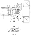
- the device 1 serves for the rotationally fixed connection of two mutually rotatable parts 2, 3, such as in particular a shaft 2, such as a motor shaft, and a pinion 3 as a second part.
- the first part 2 has an axial starting from its free end face 4 Blind bore 5, which, starting from the end face 4, is initially formed by a cylinder wall 6, which is followed by an internal toothing 7, the groove diameter of which is at most as large as the diameter of the cylinder wall 6.
- the internal toothing 7 is followed by another Inner cylinder wall 8, the diameter of which is at most as large as the diameter of the tooth tips of the toothing 7.
- a lug 9 of the second part 3 is inserted into the bore 5, which has a configuration complementary to the described configuration of the bore 5 and accordingly has an outer cylinder wall 10 with a diameter corresponding to the inner cylinder wall 6.
- This section is followed by an external toothing 11 which is complementary to the internal toothing 7.
- the shoulder 9 of the second part 3 is provided with an annular groove 13.
- the first part 1 has at least one transverse threaded bore 15, into which a grub screw 14 is screwed with an inner end 16 adapted to the annular groove 13, the end 16 of which is connected to the groove 13 of the Approach 9 attacks.
- the second part 3 is axially fixed by pulling it with an end face 17 facing the part 1 against the end face 4 of the part 2.
- the centering of the two parts 2, 3 relative to one another takes place via the cylinder wall surfaces 6, 10 and 8, 12, while the torque is carried over the toothings 7, 11. Torque entrainment and centering are therefore separated from one another in the device according to the invention.
- part 2 is a Motor shaft is to sit on a centrifugal disc or spray disc 18 to prevent an oil jet emerging from, for example, meshing teeth from reaching the shaft sealing ring 19.
- a bearing of the motor shaft 2 is designated 20.
Abstract
Description
Die Erfindung betrifft eine Vorrichtung zur koaxialen, drehfesten, axial festlegbaren Verbindung eines Ritzels mit einer Antriebswelle eines Motors über eine eingreifende Außen- und Innenverzahnung und aufeinnanderliegenden Zylinderflächen eines Ritzelfortsatzes und der Antriebswelle, mit einem Querstift.The invention relates to a device for the coaxial, rotationally fixed, axially fixable connection of a pinion with a drive shaft of a motor via an engaging external and internal toothing and superimposed cylinder surfaces of a pinion extension and the drive shaft, with a cross pin.
Bei den beiden miteinander zu verbindenden Teilen kann es sich um eine Welle, wie eine Motorwelle und insbesondere als zweites Teil um ein Ritzel handeln. Bisher wurden die entsprechenden Teile im allgemeinen durch Paßfederverbindungen oder kraftschlüssig gegen Verdrehung gesichert. Hierbei war entweder ein gewisses Spiel gegeben, oder kein Formschluß gewährleistet.The two parts to be connected to one another can be a shaft, such as a motor shaft, and in particular as a second part a pinion. So far, the corresponding parts have generally been secured by key connections or non-positively against rotation. There was either a certain amount of play, or no positive locking was guaranteed.
Die US-A-2 587 838 beschreibt einen Zapfwellenadapter für die Zapfwelle eines Schleppers. Die Verbindung des wellenartigen Adapters mit der Zapfwelle erfolgt durch eine eingreifende Außen- bzw. Innenverzahnung. Damit läßt sich jedoch nur eine für eine Ritzelbefestigung mangelhafte koaxiale Führung der beiden Teile zueinander erzielen. Zur axialen Festlegung ist ein Spannstift vorgesehen, der durch den gesamten Querschnitt durchgeschlagen wird.US-A-2 587 838 describes a PTO adapter for the PTO of a tractor. The shaft-like adapter is connected to the PTO shaft by means of an engaging external or internal toothing. However, this can only achieve poor coaxial guidance of the two parts to one another for pinion fastening. A dowel pin is provided for axial fixing, which is penetrated through the entire cross section.
Die GB-A-2 019 528 beschreibt eine Wellenkupplung, die als Schnellwechselteil zur Verwendung bei einer langsam laufenden Walzeinrichtung dient. Dabei sind die beiden Kupplungsteile 6 und 8 nicht axial zueinander festgelegt.GB-A-2 019 528 describes a shaft coupling which serves as a quick change part for use in a slow running rolling device. The two
Die EP-A1-0 088 589 beschreibt eine Anschlußeinrichtung zum Antrieb einer Viskositätskupplung. Zur Übertragung von Drehmomenten ist dabei jedoch weder eine Außen- noch eine Innenverzahnung vorgesehen.EP-A1-0 088 589 describes a connection device for driving a viscosity coupling. However, neither external nor internal toothing is provided for the transmission of torques.
Die FR-A-2 279 972 beschreibt eine Kupplungsvorrichtung für zwei zu koppelnde Hohlwellen. Dabei wird eine zentrische Schraube zur axialen Sicherung verwendet. Eine derartige Ausgestaltung ist für eine Ritzelbefestigung nicht sinnvoll, da zum einen der Ritzelquerschnitt geschwächt würde und zum anderen ein solches Ritzel nur sehr umständlich auszuwechseln wäre.FR-A-2 279 972 describes a coupling device for two hollow shafts to be coupled. A central screw is used for axial locking. Such a configuration does not make sense for a pinion attachment, since on the one hand the pinion cross section would be weakened and on the other hand such a pinion would be very difficult to replace.
Die US-A-3 847 248 beschreibt eine Schmiereinrichtung für eine Mitnehmerverbindung zwischen einem Ritzel und einer Welle. Die Mitnehmerverbindung ist durch Splinte bzw. Paßfedern realisiert. Solche Verbindungen sind ungeeignet für wechselnde Drehmomentbelastungen aufgrund der dabei auftretenden Relativbewegung zwischen Welle und Ritzel. Dabei ist das Ritzel durch aufeinanderliegende Zylinderflächen koaxial zur Welle geführt und durch einen Sprengring gegen axiales Verschieben gesichert.US-A-3 847 248 describes a lubrication device for a driver connection between a pinion and a shaft. The driver connection is realized by split pins or feather keys. Such connections are unsuitable for changing torque loads due to the relative movement that occurs between the shaft and pinion. The pinion is by lying on top of each other Cylinder surfaces are guided coaxially to the shaft and secured against axial displacement by a snap ring.
Die GB-A-1 205 199 beschreibt eine Verriegelungsvorrichtung für Wellen mit hohen Drehzahlen. Dabei wird ein Hohlritzel beschrieben, das mit einer Innenverzahnung versehen auf einer entsprechend angepaßten Welle mit Außenverzahnung sitzt. Der koaxialen Führung dient eine Hohlzylinderfläche des Hohlritzels, die auf einer entsprechenden Außenzylinderfläche der Welle anliegt, und eine zweite Hohlzylinderfläche, die auf einer Außenzylinderfläche eines Sicherungsteils anliegt (Fig. 1).GB-A-1 205 199 describes a locking device for high speed shafts. Here, a hollow pinion is described, which is provided with internal teeth on a correspondingly adapted shaft with external teeth. The coaxial guide is served by a hollow cylindrical surface of the hollow pinion, which rests on a corresponding outer cylindrical surface of the shaft, and a second hollow cylindrical surface, which rests on an outer cylindrical surface of a securing part (FIG. 1).
Die DE-C-3 712 195 beschreibt eine Vorrichtung zur Feineinstellung der Drehwinkellage einer Welle zu einem mit dieser gleichachsig lösbar verbundenen Bauteil. Diese Vorrichtung ist insbesondere zur Einstellung der Drehwinkellage einer Lenkradnabe zu einer Lenkwelle gedacht. Dabei wird eine Buchse mit Außen- und Innenverzahnung zwischen Lenkwelle und Lenkradnabe angeordnet. Hierbei weist die Welle eine Außenverzahnung und die Lenkradnabe eine Innenverzahnung auf. Die Zentrierung der Lenkradnabe erfolgt über eine Innenzylinderfläche und eine Schrägfläche.DE-C-3 712 195 describes a device for fine adjustment of the angular position of a shaft to a component detachably connected to it on the same axis. This device is intended in particular for adjusting the angular position of a steering wheel hub relative to a steering shaft. A bushing with external and internal teeth is arranged between the steering shaft and steering wheel hub. Here, the shaft has external teeth and the steering wheel hub has internal teeth. The steering wheel hub is centered via an inner cylinder surface and an inclined surface.
Die DE-A-3 711 163 beschreibt eine Vorrichtung zum lösbaren Festspannen von scheiben- oder ringförmigen Walzen. Dabei wird eine drehfeste Verbindung zwischen einer Walze und einer Welle durch Reibschluß mittels einer vorgespannten Buchse realisiert.DE-A-3 711 163 describes a device for releasably tightening disk-shaped or ring-shaped rollers. In this case, a rotationally fixed connection between a roller and a shaft is realized by frictional engagement by means of a prestressed bush.
Die FR-A-1 304 987 beschreibt eine Welle mit Außenverzahnung und ein weiteres Teil mit einer angepaßten Innenverzahnung. Die Verzahnungen sind so ausgeführt, daß eine koaxiale Führung des Teils bezüglich der Welle gegeben ist. Dabei erfolgt eine axiale Festlegung nur in einer Richtung.FR-A-1 304 987 describes a shaft with external teeth and another part with an adapted internal teeth. The teeth are designed so that there is coaxial guidance of the part with respect to the shaft. In this case, an axial fixing takes place only in one direction.
Der Erfindung liegt die Aufgabe zugrunde, eine Vorrichtung zur lösbaren Verbindung eines Ritzels mit einer Antriebswelle zu schaffen, die eine gute Zentrierung und spielfreie, formschlüssige Verbindung beider Teile in einfacher Weise ermöglicht.The invention has for its object to provide a device for releasably connecting a pinion to a drive shaft, which enables good centering and play-free, positive connection of both parts in a simple manner.
Erfindungsgemäß wird die genannte Aufgabe bei einer Vorrichtung der eingangs genannten Art dadurch gelöst, daß der Ritzelfortsatz zwei Außenzylinderwandungen und eine zwischen diesen angeordnete Außenverzahnung aufweist, daß die dem Ritzel nächstliegende Außenzylinderwandung des Ritzelfortsatzes einen größeren Durchmesser als die andere Außenzylinderwandung aufweist, daß die Antriebswelle am freien Ende zur Aufnahme des Wellenfortsatzes mit einer axialen Blindbohrung versehen ist, die mit zwei den Außenzylinderwänden angepaßten Hohlzylinderabschnitten und einer dazwischenliegenden Innenverzahnung so ausgebildet ist, daß bei eingestecktem Wellenfortsatz die Innen- und Außenverzahnungen zum Eingriff kommen und die beidseits derselben angeordneten Hohlzylinderabschnitte und entsprechenden Außenzylinderwandungen die koaxiale Führung des Ritzels bezüglich der Antriebswelle gewährleisten, daß der Querstift ein Quergewindestift ist, der in die Antriebswelle eingeschraubt ist und eine konische bzw. kegelstumpfartige Spitze aufweist, daß die dem Ritzel entferntere Außenzylinderwandung des Ritzelfortsatzes eine Ringnut mit an die Spitze angepaßtem Querschnitt zur Aufnahme des Quergewindestifts als Arretierungsmittel zur axialen Festlegung des Ritzels bezüglich der Antriebswelle aufweist, und daß die Achse des Quergewindestifts bei eingestrecktem Ritzelfortsatz in Richtung dessen freien Endes bezüglich der Zentralebene der Ringnut versetzt angeordnet ist, so daß bei eingedrehtem Quergewindestift Stirnseiten des Ritzels und der Antriebswelle als Widerlager zur Axialbefestigung gegeneinander verspannt sind.According to the invention, the stated object is achieved in a device of the type mentioned in the introduction in that the pinion extension has two outer cylinder walls and an external toothing arranged between them, in that the outer cylinder wall of the pinion extension closest to the pinion has a larger diameter than the other outer cylinder wall in that the drive shaft is free End for receiving the shaft extension is provided with an axial blind bore, which is designed with two hollow cylinder sections adapted to the outer cylinder walls and an internal toothing in between, so that when the shaft extension is inserted, the inner and outer toothings come into engagement and the hollow cylinder sections arranged on both sides and corresponding outer cylinder walls provide the coaxial Guide the pinion with respect to the drive shaft ensure that the cross pin is a cross grub screw that is screwed into the drive shaft t is and has a conical or frustoconical tip that the outer cylinder wall of the pinion extension, which is more distant from the pinion, has an annular groove with a cross section adapted to the tip for receiving the cross-threaded pin as a locking means for axially fixing the pinion with respect to the drive shaft, and that the axis of the cross-threaded pin is at stretched pinion extension towards it Free end is offset with respect to the central plane of the annular groove, so that when the transverse grub screw is screwed in, the front sides of the pinion and the drive shaft are braced against one another as an abutment for axial fastening.
Durch die erfindungsgemäße Ausgestaltung wird die Zentrierung der beiden miteinander zu verbindenden Teile über die Zylinderwandungen von der Drehmomentmitnahme über die Verzahnungsausbildungen getrennt. Hierdurch wird eine gute Zentrierung erreicht und eine spielfreie Drehmomentmitnahme ermöglicht. Die Verzahnungsausbildungen können in vielfältiger Weise ausgestaltet sein, als Vielteilprofile, als Evolventenverzahnungen, Zykloidenverzahnungen, Polygonprofile od.dgl.The configuration according to the invention separates the centering of the two parts to be connected to one another via the cylinder walls from the torque entrainment via the toothing designs. Good centering is achieved in this way and torque-free play is possible. The toothing designs can be designed in a variety of ways, as many-part profiles, as involute teeth, cycloid teeth, polygon profiles or the like.
Weitere Vorteile und Merkmale der Erfindung ergeben sich aus der nachfolgenden Beschreibung, in der ein Ausführungsbeispiel der Erfindung unter Bezugnahme auf die Zeichnung im einzelnen erläutert ist. Dabei zeigt:
Figur 1- Einen Längsschnitt durch die erfindungsgemäße Verbindungsvorrichtung; und
Figur 2- einen Schnitt durch die Verzahnung entsprechend II-II der
Figur 1.
- Figure 1
- A longitudinal section through the connecting device according to the invention; and
- Figure 2
- a section through the toothing corresponding to II-II of Figure 1.
Die erfindungsgemäße Vorrichtung 1 dient zur drehfesten Verbindung zweier miteinander drehbarer Teile 2,3, wie insbesondere einer Welle 2, wie einer Motorwelle, und einem Ritzel 3 als zweites Teil. Das erste Teil 2 weist von seiner freien Stirnseite 4 ausgehend eine axiale Blindbohrung 5 auf, welche von der Stirnseite 4 ausgehend zunächst durch eine Zylinderwandung 6 gebildet ist, an die sich eine Innenverzahnung 7 anschließt, deren Nutendurchmesser höchstens so groß ist wie der Durchmesser der Zylinderwandung 6. Im dargestellten Ausführungsbeispiel schließt sich an die Innenverzahnung 7 eine weitere Innenzylinderwandung 8 an, deren Durchmesser höchstens so groß ist wie der Durchmesser der Zahnköpfe der Verzahnung 7.The
In die Bohrung 5 ist ein Ansatz 9 des zweiten Teils 3 eingesetzt, der eine zu der beschriebenen Ausgestaltung der Bohrung 5 komplementäre Ausgestaltung und demgemäß eine Außenzylinderwandung 10 mit einem der Innenzylinderwandung 6 entsprechenden Durchmesser aufweist. Diesem Abschnitt schließt sich eine Außenverzahnung 11 an, die komplementär zur Innenverzahnung 7 ausgebildet ist. Hierauf folgt eine äußere Zylinderwandung 12 mit einem dem Durchmesser der Innenzylinderwandung 8 entsprechenden äußeren Durchmesser. An seinem freien Ende ist der Ansatz 9 des zweiten Teils 3 mit einer Ringnut 13 versehen. Auf der axialen Höhe der Ringnut 13 des Ansatzes 9 weist das erste Teil 1 zumindestens eine Quergewindebohrung 15 auf, in die ein Gewindestift 14 mit einem an die Ringnut 13 angepaßten, inneren Ende 16 eingeschraubt ist, der mit seinem Ende 16 an der Nut 13 des Ansatzes 9 angreift. Hierdurch wird das zweite Teil 3 axial festgelegt, indem es mit einer dem Teil 1 zugewandten Stirnseite 17 gegen die Stirnseite 4 des Teils 2 gezogen wird. Die Zentrierung der beiden Teile 2,3 relativ zueinander erfolgt über die Zylinderwandungsflächen 6,10 und 8, 12, während die Drehmomentmitnahme über die Verzahnungen 7,11 erfolgt. Drehmomentmitnahme und Zentrierung sind daher bei der erfindungsgemäßen Vorrichtung voneinander getrennt. Auf dem ersten Teil kann, wenn das Teil 2 eine Motorwelle ist, eine Schleuderscheibe oder Spritzscheibe 18 aufsitzen, um zu verhindern, daß ein aus dem z.B. Zahneingriff austretenden Ölstrahl an den Wellendichtring 19 gelangt. Ein Lager der Motorwelle 2 ist mit 20 bezeichnet.A
Claims (1)
- Device (1) for the coaxial, rotation-fixed, axially fixable connection of a pinion (3) to a driving shaft (2) of a motor by means of an engaging external and internal tooth system (7, 11) and mating cylinder surfaces (6, 10, 8, 12) of a pinion extension (9) and the driving shaft (2), with a transverse pin (14), characterized in that the pinion extension (9) has two outer cylinder walls (10, 12) and an external tooth system (11) positioned between them, that the outer cylinder wall (10) of the pinion extension (9) closer to the pinion (3) has a larger diameter than the other outer cylinder wall (12), that for receiving the pinion extension (9) the free end of the driving shaft (2) is provided with an axial blind hole (5), which is so constructed with two hollow cylinder portions (6, 8) adapted to the outer cylinder walls (10, 12) and an interposed internal tooth system (7) that when the pinion extension (9) is inserted engagement occurs between the internal and external tooth systems (7, 11) and the hollow cylinder portions (6, 8) arranged on either side thereof and the corresponding outer cylinder walls (10, 12) ensure the coaxial guidance of the pinion (3) with respect to the driving shaft (2), that the transverse pin is a transverse threaded pin (14), which is screwed into the driving shaft (2) and has a conical or frustum-like tip (16), that the outer cylinder wall (12) of the pinion extension (9) further removed from the pinion (3) has a circular groove (13) with a cross-section adapted to the tip (16) for receiving the transverse threaded pin (14) as an arresting means for the axial fixing of the pinion (3) relative to the driving shaft (2) and that the axis of the transverse threaded pin (14) with inserted pinion extension (9) in the direction of its free end is displaced with respect to the central plane of the circular groove (13), so that with the transverse threaded pin (14) inserted the front faces (4, 17) of the pinion (3) and the driving shaft (2) are braced against one another as abutments for axial fixing.
Priority Applications (1)
| Application Number | Priority Date | Filing Date | Title |
|---|---|---|---|
| AT89106589T ATE82621T1 (en) | 1988-04-28 | 1989-04-13 | DEVICE FOR COAXIAL ROTATIONAL CONNECTION OF TWO PARTS. |
Applications Claiming Priority (2)
| Application Number | Priority Date | Filing Date | Title |
|---|---|---|---|
| DE8805632U | 1988-04-28 | ||
| DE8805632U DE8805632U1 (en) | 1988-04-28 | 1988-04-28 |
Publications (2)
| Publication Number | Publication Date |
|---|---|
| EP0339380A1 EP0339380A1 (en) | 1989-11-02 |
| EP0339380B1 true EP0339380B1 (en) | 1992-11-19 |
Family
ID=6823480
Family Applications (1)
| Application Number | Title | Priority Date | Filing Date |
|---|---|---|---|
| EP89106589A Expired - Lifetime EP0339380B1 (en) | 1988-04-28 | 1989-04-13 | Device for connecting two machine parts to rotate together and about the same axis |
Country Status (7)
| Country | Link |
|---|---|
| EP (1) | EP0339380B1 (en) |
| AT (1) | ATE82621T1 (en) |
| DE (2) | DE8805632U1 (en) |
| DK (1) | DK203889A (en) |
| FI (1) | FI891826A (en) |
| NO (1) | NO171327C (en) |
| PT (1) | PT90385A (en) |
Cited By (7)
| Publication number | Priority date | Publication date | Assignee | Title |
|---|---|---|---|---|
| DE10137025C1 (en) * | 2001-07-30 | 2002-12-05 | Sew Eurodrive Gmbh & Co | Shaft component set provided by different component sizes with different shaft variations for each size |
| WO2003100278A1 (en) | 2002-05-24 | 2003-12-04 | Sew-Eurodrive Gmbh & Co | Series of shafts and method for manufacturing the same |
| DE10302072B3 (en) * | 2002-12-20 | 2004-09-09 | Sew-Eurodrive Gmbh & Co Kg | Shaft for fixing in a bore of a receiving part interlocks with the bore of the receiving part |
| DE102005059018B4 (en) * | 2005-12-08 | 2008-06-12 | Sew-Eurodrive Gmbh & Co. Kg | Electric motor and connection between a rotor shaft and a rotor core |
| DE102008040321A1 (en) * | 2008-07-10 | 2010-01-14 | Sumitomo (Shi) Cyclo Drive Germany Gmbh | Pinion attachment for planetary gear, has pinion provided with shaft stub, and hollow shaft whose region is provided with phase at open end so that diameter of region of hollow shaft is larger than diameter of open end |
| DE102015109101A1 (en) * | 2015-06-09 | 2016-12-15 | Ebm-Papst St. Georgen Gmbh & Co. Kg | Drive device and method for mounting a drive device |
| DE102021201766A1 (en) | 2021-02-25 | 2022-08-25 | Zf Friedrichshafen Ag | Spline with oil catch groove |
Families Citing this family (11)
| Publication number | Priority date | Publication date | Assignee | Title |
|---|---|---|---|---|
| DE4106096C1 (en) * | 1991-02-27 | 1992-10-15 | Jean Walterscheid Gmbh, 5204 Lohmar, De | |
| DE4419372C2 (en) * | 1994-06-03 | 1998-01-29 | Loehr & Bromkamp Gmbh | Device for connecting a tubular shaft to a pin |
| DE29501158U1 (en) * | 1995-01-25 | 1995-03-30 | Electrolux Corporate Patents & | Locking device for a drive shaft |
| FR2753753B1 (en) * | 1996-09-24 | 1999-01-08 | SYSTEM FOR MECHANICALLY LOCKING A SLEEVE ON A DRIVE SHAFT | |
| DE29808420U1 (en) | 1998-05-05 | 1998-07-30 | Petri Ag | Device for fastening a hub on a shaft, in particular a steering wheel hub on a steering column |
| DE19836259C2 (en) * | 1998-08-11 | 2001-02-01 | Christoph Puls | Non-rotatable shaft-hub connection |
| DE19848324B4 (en) * | 1998-10-20 | 2007-03-22 | Sew-Eurodrive Gmbh & Co. Kg | clutch |
| US6883604B2 (en) * | 2001-06-05 | 2005-04-26 | Baker Hughes Incorporated | Shaft locking couplings for submersible pump assemblies |
| DE102010047008A1 (en) | 2010-09-30 | 2012-04-05 | Ims Gear Gmbh | Connection structure for the mechanical connection of a first housing with a second housing |
| DE102012012293B4 (en) * | 2012-06-20 | 2017-10-26 | Sms Group Gmbh | Device for forming a workpiece |
| CN107319920A (en) * | 2017-08-14 | 2017-11-07 | 王晓杰 | A kind of small-sized instant noodle makes and sell machine |
Family Cites Families (9)
| Publication number | Priority date | Publication date | Assignee | Title |
|---|---|---|---|---|
| US2587838A (en) * | 1950-09-20 | 1952-03-04 | Hub City Iron Company | Spline adapter coupler |
| FR1304987A (en) * | 1961-11-03 | 1962-09-28 | Ministerul Metalurgiei Si Cons | Rigid assembly using involute flanks |
| NL6910542A (en) * | 1968-07-11 | 1970-01-13 | ||
| US3847248A (en) * | 1973-08-23 | 1974-11-12 | Caterpillar Tractor Co | Replaceable lubricating cartridge for spline connections |
| DE2436270A1 (en) * | 1974-07-27 | 1976-02-05 | Motoren Turbinen Union | SHAFT CONNECTION |
| GB2019528B (en) * | 1978-04-21 | 1982-07-14 | Davy Loewy Ltd | Shaft couplings |
| EP0088589A1 (en) * | 1982-03-10 | 1983-09-14 | Eaton Corporation | Mounting shaft and adaptor for viscous coupling |
| DE3711163A1 (en) * | 1987-04-02 | 1988-10-20 | Kocks Technik | Device for detachable clamping of disc-shaped or annular rollers |
| DE3712195C1 (en) * | 1987-04-10 | 1988-07-07 | Daimler Benz Ag | Device for fine adjustment of the angular position of a shaft to a component connected to it in a coaxial manner |
-
1988
- 1988-04-28 DE DE8805632U patent/DE8805632U1/de not_active Expired
-
1989
- 1989-04-13 AT AT89106589T patent/ATE82621T1/en not_active IP Right Cessation
- 1989-04-13 EP EP89106589A patent/EP0339380B1/en not_active Expired - Lifetime
- 1989-04-13 DE DE8989106589T patent/DE58902738D1/en not_active Expired - Lifetime
- 1989-04-17 FI FI891826A patent/FI891826A/en not_active IP Right Cessation
- 1989-04-26 NO NO891739A patent/NO171327C/en unknown
- 1989-04-27 DK DK203889A patent/DK203889A/en not_active Application Discontinuation
- 1989-04-27 PT PT90385A patent/PT90385A/en not_active Application Discontinuation
Cited By (9)
| Publication number | Priority date | Publication date | Assignee | Title |
|---|---|---|---|---|
| DE10137025C1 (en) * | 2001-07-30 | 2002-12-05 | Sew Eurodrive Gmbh & Co | Shaft component set provided by different component sizes with different shaft variations for each size |
| WO2003100278A1 (en) | 2002-05-24 | 2003-12-04 | Sew-Eurodrive Gmbh & Co | Series of shafts and method for manufacturing the same |
| DE10316155B4 (en) * | 2002-05-24 | 2006-04-20 | Sew-Eurodrive Gmbh & Co. Kg | Shaft, series of shafts and manufacturing process |
| DE10302072B3 (en) * | 2002-12-20 | 2004-09-09 | Sew-Eurodrive Gmbh & Co Kg | Shaft for fixing in a bore of a receiving part interlocks with the bore of the receiving part |
| DE102005059018B4 (en) * | 2005-12-08 | 2008-06-12 | Sew-Eurodrive Gmbh & Co. Kg | Electric motor and connection between a rotor shaft and a rotor core |
| DE102008040321A1 (en) * | 2008-07-10 | 2010-01-14 | Sumitomo (Shi) Cyclo Drive Germany Gmbh | Pinion attachment for planetary gear, has pinion provided with shaft stub, and hollow shaft whose region is provided with phase at open end so that diameter of region of hollow shaft is larger than diameter of open end |
| DE102008040321B4 (en) * | 2008-07-10 | 2010-12-02 | Sumitomo (Shi) Cyclo Drive Germany Gmbh | Pinion mounting for planetary gear |
| DE102015109101A1 (en) * | 2015-06-09 | 2016-12-15 | Ebm-Papst St. Georgen Gmbh & Co. Kg | Drive device and method for mounting a drive device |
| DE102021201766A1 (en) | 2021-02-25 | 2022-08-25 | Zf Friedrichshafen Ag | Spline with oil catch groove |
Also Published As
| Publication number | Publication date |
|---|---|
| PT90385A (en) | 1989-11-10 |
| FI891826A0 (en) | 1989-04-17 |
| DE8805632U1 (en) | 1988-06-09 |
| DE58902738D1 (en) | 1992-12-24 |
| FI891826A (en) | 1989-10-29 |
| EP0339380A1 (en) | 1989-11-02 |
| ATE82621T1 (en) | 1992-12-15 |
| NO171327B (en) | 1992-11-16 |
| DK203889A (en) | 1989-10-29 |
| NO891739L (en) | 1989-10-30 |
| NO171327C (en) | 1993-02-24 |
| NO891739D0 (en) | 1989-04-26 |
| DK203889D0 (en) | 1989-04-27 |
Similar Documents
| Publication | Publication Date | Title |
|---|---|---|
| EP0339380B1 (en) | Device for connecting two machine parts to rotate together and about the same axis | |
| EP0747606B1 (en) | Fastening for securing a coupling sleeve | |
| DE3246233C2 (en) | ||
| EP2142386B1 (en) | Bearing arrangement for a motor vehicle with a wheel hub drivable by a rotating joint | |
| DE1931300C3 (en) | Motor vehicle wheel bearings | |
| WO2008148373A1 (en) | Device for the rotationally fixed connection of a pin of a gearbox to an articulated body of a drive coupling of a drive shaft | |
| DE19648998B4 (en) | Arrangement applicable to telescopic waves | |
| DE10258515A1 (en) | planetary gear | |
| DE1450122A1 (en) | Precision shaft collar and this using precision gear | |
| DE3626851A1 (en) | Device for fixing rotary grinding tools, in particular grinding wheels, on a spindle | |
| DE2348731C2 (en) | Edge processing tool | |
| DE602004013062T2 (en) | Cross pin mounting system for differentials | |
| EP0790423A1 (en) | Method for producing a device for the connection of a splined torque transmitting shaft end | |
| DE3835544C1 (en) | ||
| EP1360424B1 (en) | Flange driver for universal joints | |
| EP0480159A1 (en) | Device for the introduction of a steering compensation | |
| DE2940762C2 (en) | Pre-tensionable double nut for ball screw spindles | |
| DE3916315A1 (en) | Tool shank for milling cutters - has regular curvilinear polygonal collar positively engaging with matching bore in spindle nose | |
| DE3806259C1 (en) | ||
| EP0062109A1 (en) | Releasable coupling for the transmission of high torques | |
| DE19709282A1 (en) | Propeller shaft with two universal joints for e.g. rail vehicles | |
| EP1003650A1 (en) | Front-axle output of an automatic transmission | |
| EP0489007A1 (en) | Torsion-proof flanged connection | |
| DE10107307B4 (en) | flange yoke | |
| EP0877173A1 (en) | Power transmission fibre-reinforced shaft |
Legal Events
| Date | Code | Title | Description |
|---|---|---|---|
| PUAI | Public reference made under article 153(3) epc to a published international application that has entered the european phase |
Free format text: ORIGINAL CODE: 0009012 |
|
| AK | Designated contracting states |
Kind code of ref document: A1 Designated state(s): AT BE CH DE ES FR GB GR IT LI LU NL SE |
|
| 17P | Request for examination filed |
Effective date: 19900428 |
|
| 17Q | First examination report despatched |
Effective date: 19910718 |
|
| GRAA | (expected) grant |
Free format text: ORIGINAL CODE: 0009210 |
|
| AK | Designated contracting states |
Kind code of ref document: B1 Designated state(s): AT BE CH DE ES FR GB GR IT LI LU NL SE |
|
| PG25 | Lapsed in a contracting state [announced via postgrant information from national office to epo] |
Ref country code: GR Free format text: LAPSE BECAUSE OF FAILURE TO SUBMIT A TRANSLATION OF THE DESCRIPTION OR TO PAY THE FEE WITHIN THE PRESCRIBED TIME-LIMIT Effective date: 19921119 Ref country code: NL Effective date: 19921119 Ref country code: BE Effective date: 19921119 Ref country code: GB Effective date: 19921119 Ref country code: FR Effective date: 19921119 Ref country code: SE Effective date: 19921119 Ref country code: ES Free format text: THE PATENT HAS BEEN ANNULLED BY A DECISION OF A NATIONAL AUTHORITY Effective date: 19921119 Ref country code: IT Free format text: LAPSE BECAUSE OF FAILURE TO SUBMIT A TRANSLATION OF THE DESCRIPTION OR TO PAY THE FEE WITHIN THE PRE;WARNING: LAPSES OF ITALIAN PATENTS WITH EFFECTIVE DATE BEFORE 2007 MAY HAVE OCCURRED AT ANY TIME BEFORE 2007. THE CORRECT EFFECTIVE DATE MAY BE DIFFERENT FROM THE ONE RECORDED.SCRIBED TIME-LIMIT Effective date: 19921119 |
|
| REF | Corresponds to: |
Ref document number: 82621 Country of ref document: AT Date of ref document: 19921215 Kind code of ref document: T |
|
| REF | Corresponds to: |
Ref document number: 58902738 Country of ref document: DE Date of ref document: 19921224 |
|
| EN | Fr: translation not filed | ||
| PG25 | Lapsed in a contracting state [announced via postgrant information from national office to epo] |
Ref country code: AT Effective date: 19930413 |
|
| NLV1 | Nl: lapsed or annulled due to failure to fulfill the requirements of art. 29p and 29m of the patents act | ||
| PG25 | Lapsed in a contracting state [announced via postgrant information from national office to epo] |
Ref country code: LI Effective date: 19930430 Ref country code: LU Free format text: LAPSE BECAUSE OF NON-PAYMENT OF DUE FEES Effective date: 19930430 Ref country code: CH Effective date: 19930430 |
|
| GBV | Gb: ep patent (uk) treated as always having been void in accordance with gb section 77(7)/1977 [no translation filed] |
Effective date: 19921119 |
|
| PLBE | No opposition filed within time limit |
Free format text: ORIGINAL CODE: 0009261 |
|
| STAA | Information on the status of an ep patent application or granted ep patent |
Free format text: STATUS: NO OPPOSITION FILED WITHIN TIME LIMIT |
|
| 26N | No opposition filed | ||
| REG | Reference to a national code |
Ref country code: CH Ref legal event code: PL |
|
| PGFP | Annual fee paid to national office [announced via postgrant information from national office to epo] |
Ref country code: DE Payment date: 20080626 Year of fee payment: 20 |