EP0339320B1 - Tige de prothèse - Google Patents
Tige de prothèse Download PDFInfo
- Publication number
- EP0339320B1 EP0339320B1 EP89105993A EP89105993A EP0339320B1 EP 0339320 B1 EP0339320 B1 EP 0339320B1 EP 89105993 A EP89105993 A EP 89105993A EP 89105993 A EP89105993 A EP 89105993A EP 0339320 B1 EP0339320 B1 EP 0339320B1
- Authority
- EP
- European Patent Office
- Prior art keywords
- shaft
- prosthesis
- bone
- cement
- spheres
- Prior art date
- Legal status (The legal status is an assumption and is not a legal conclusion. Google has not performed a legal analysis and makes no representation as to the accuracy of the status listed.)
- Expired - Lifetime
Links
Images


Classifications
-
- A—HUMAN NECESSITIES
- A61—MEDICAL OR VETERINARY SCIENCE; HYGIENE
- A61F—FILTERS IMPLANTABLE INTO BLOOD VESSELS; PROSTHESES; DEVICES PROVIDING PATENCY TO, OR PREVENTING COLLAPSING OF, TUBULAR STRUCTURES OF THE BODY, e.g. STENTS; ORTHOPAEDIC, NURSING OR CONTRACEPTIVE DEVICES; FOMENTATION; TREATMENT OR PROTECTION OF EYES OR EARS; BANDAGES, DRESSINGS OR ABSORBENT PADS; FIRST-AID KITS
- A61F2/00—Filters implantable into blood vessels; Prostheses, i.e. artificial substitutes or replacements for parts of the body; Appliances for connecting them with the body; Devices providing patency to, or preventing collapsing of, tubular structures of the body, e.g. stents
- A61F2/02—Prostheses implantable into the body
- A61F2/30—Joints
- A61F2/32—Joints for the hip
- A61F2/36—Femoral heads ; Femoral endoprostheses
- A61F2/3662—Femoral shafts
-
- A—HUMAN NECESSITIES
- A61—MEDICAL OR VETERINARY SCIENCE; HYGIENE
- A61F—FILTERS IMPLANTABLE INTO BLOOD VESSELS; PROSTHESES; DEVICES PROVIDING PATENCY TO, OR PREVENTING COLLAPSING OF, TUBULAR STRUCTURES OF THE BODY, e.g. STENTS; ORTHOPAEDIC, NURSING OR CONTRACEPTIVE DEVICES; FOMENTATION; TREATMENT OR PROTECTION OF EYES OR EARS; BANDAGES, DRESSINGS OR ABSORBENT PADS; FIRST-AID KITS
- A61F2/00—Filters implantable into blood vessels; Prostheses, i.e. artificial substitutes or replacements for parts of the body; Appliances for connecting them with the body; Devices providing patency to, or preventing collapsing of, tubular structures of the body, e.g. stents
- A61F2/02—Prostheses implantable into the body
- A61F2/30—Joints
- A61F2/32—Joints for the hip
- A61F2/36—Femoral heads ; Femoral endoprostheses
- A61F2/3609—Femoral heads or necks; Connections of endoprosthetic heads or necks to endoprosthetic femoral shafts
- A61F2002/3625—Necks
- A61F2002/3631—Necks with an integral complete or partial peripheral collar or bearing shoulder at its base
Definitions
- the invention relates to a prosthesis socket for implanting a prosthesis, in particular an artificial hip, knee or finger joint part using a bone cement.
- the shaft to be anchored in the bone has an essentially smooth, conically shaped surface.
- FIGS. 1 and 2 using a hip prosthesis as an example, it is shown schematically which holding forces occur on the surface of the shaft 10 when a force P is applied to the joint ball 11.
- These holding forces can be calculated from the bending moment, i.e. the force P times the distance e of the direction of action from the shaft axis, the resulting compressive forces (+) and tensile forces (-) and the shear forces ( ⁇ ⁇ ) resulting from the axial force P on the shaft surface.
- the actual load on the bone anchoring the stem results from the superposition of these compressive, tensile and shear forces.
- a prosthesis socket according to the preamble of claim 1 is known from WO-A-8 600 011.
- Known bone cements can transmit compressive and tensile forces almost equally well and can also absorb shear forces relatively easily.
- a major disadvantage of the known bone cements, however, is that they attack the bone, so that the lifespan of the anchoring is limited and later anchoring is no longer possible due to the partially destroyed bone end.
- Such a prosthesis is known from DE-A-2 461 339, the shaft of which consists essentially of a flat metal plate in the bone and is provided with rounded steps on its narrow sides. These steps are designed so that they each have an edge surface directed perpendicular to the trajectory-oriented cancellous bone structure for the direct transmission of the local compressive and tensile forces.
- the overall sawtooth-like design of the edge surfaces produced in this way should also have the effect that the total contact surface between the shaft and bone tissue is enlarged and the pressures acting thereon are correspondingly lower.
- cement-free anchoring aimed at with such a shaft requires good growth of the bone tissue so that the sawtooth-like shaft surfaces are securely embedded in the desired manner. Even if this condition is initially met, there is always a risk of cementless anchoring loosening over time.
- a generally hollow cylindrical bone dowel which has an internal thread for screwing in a bone screw and the outer surface of which is formed by a plurality of partially penetrating large spherical surfaces and with axial and / or transverse slots and additional unevenness, in particular in Shape of small balls, is provided.
- This design is intended to achieve the most intimate connection possible with the remaining bone tissue so that the cement-free anchored part of the prosthesis grows in well. Again, sufficient bone growth is assumed and the risk of loosening later is always accepted.
- glass ionomers as bone cements, which are bio-inert and therefore, in contrast to conventional cements, do not attack the bone tissue.
- Glass ionomer bone cements have very good compressive strength, but only low tensile strength and a pronounced brittle fracture behavior.
- the invention has for its object to design a prosthesis socket so that it can be used of a glass ionomer bone cement can be securely and permanently anchored in the bone.
- joint ball 20 is connected via a leg 21 to a shaft generally designated 22.
- Joint ball 20, leg 21 and shaft 22 can be formed in one piece or can also be composed of individual parts, e.g. screwed together.
- the upper part of the shaft surface is made up of a plurality of spherical surfaces 23, 24, 25 which merge into one another.
- the transition regions 26, 27, 28, 29 are between the individual spherical surfaces 23... 25, between the uppermost spherical surface 23 and the proximal shaft section 30 connected to the leg 21, and between the lowermost spherical surface 25 and the slightly conical distal shaft section 31 designed as a concave rounded ring surface.
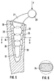
- the shape of the shaft is based on the knowledge that when a ball is pressed into a viscous material, only radial pressure forces arise. this is also valid when several such balls are arranged one behind the other along the shaft axis. As indicated by the symbols (+) in the schematic illustration in FIG. 5, even with such an arrangement of a plurality of balls, only compressive forces occur at practically all locations in the bone cement denoted by 32. When the force P shown in FIG. 5 is applied to the joint ball 20, each ball of the shaft, with its lower half, exclusively generates pressure forces. Furthermore, the respective upper ball is supported on the lower ball via the bone cement 32, so that compressive stresses are also present in the area between the balls.
- the schematic representation of FIG. 5 also clearly shows that the balls or spherical surfaces 23... 25 have a decreasing radius from the proximal to the distal shaft end and only penetrate one another to such an extent that the centers of the respective neighboring spheres lie outside the mutual penetration area . Furthermore, it is expedient that the spheres _ as far as the cavity 33 available in the bone allows this _ each have the largest possible radii.
- the cavity 33 mentioned is essentially the natural cavity freed from bone marrow, the surface of which can be roughened to achieve a more intimate connection with the bone cement 32.
- At least one of the balls in its cross section shown in FIG. 6 is flattened in an ellipsoidal manner or is shaped asymmetrically in some other way.
- This flattened body is arranged in the middle of the longitudinal shaft so that the forces introduced from the torsional moments can be safely absorbed. It is easiest to absorb additional forces in this area without fear of the material breaking out.
- the flattened body in the exemplary embodiment according to FIG. 5 is the central ball 24.
- FIG. 4 shows an example of a design of the prosthesis shaft 35 for a finger joint.
- the shaft 35 itself is essentially analogous in a corresponding reduction 3, the distal shaft section 31 shown in FIG. 3 being omitted because of the shorter bone length available and because of the lower forces that occur.
- the proximal joint part 36 attached to the shaft is designed in accordance with the natural joint shell.
Claims (5)
Priority Applications (1)
| Application Number | Priority Date | Filing Date | Title |
|---|---|---|---|
| AT89105993T ATE64846T1 (de) | 1988-04-27 | 1989-04-05 | Prothesenschaft. |
Applications Claiming Priority (2)
| Application Number | Priority Date | Filing Date | Title |
|---|---|---|---|
| DE8805583U DE8805583U1 (fr) | 1988-04-27 | 1988-04-27 | |
| DE8805583U | 1988-04-27 |
Publications (3)
| Publication Number | Publication Date |
|---|---|
| EP0339320A2 EP0339320A2 (fr) | 1989-11-02 |
| EP0339320A3 EP0339320A3 (en) | 1990-02-28 |
| EP0339320B1 true EP0339320B1 (fr) | 1991-07-03 |
Family
ID=6823439
Family Applications (1)
| Application Number | Title | Priority Date | Filing Date |
|---|---|---|---|
| EP89105993A Expired - Lifetime EP0339320B1 (fr) | 1988-04-27 | 1989-04-05 | Tige de prothèse |
Country Status (7)
| Country | Link |
|---|---|
| US (1) | US4978359A (fr) |
| EP (1) | EP0339320B1 (fr) |
| JP (1) | JPH01313052A (fr) |
| AT (1) | ATE64846T1 (fr) |
| CA (1) | CA1328542C (fr) |
| DE (2) | DE8805583U1 (fr) |
| ES (1) | ES2023021B3 (fr) |
Families Citing this family (9)
| Publication number | Priority date | Publication date | Assignee | Title |
|---|---|---|---|---|
| US5133766A (en) * | 1991-03-04 | 1992-07-28 | Halpern Alan A | Femoral head remodeling and femoral insert and drilling aid therefor |
| JPH07155341A (ja) * | 1993-12-07 | 1995-06-20 | Katsunari Nishihara | 人工骨 |
| JPH07155342A (ja) * | 1993-12-08 | 1995-06-20 | Katsunari Nishihara | 人工骨 |
| DE19740689A1 (de) * | 1997-09-16 | 1999-03-18 | Franz Prof Dr Med Copf | Oberschenkelprothese |
| US6200350B1 (en) * | 1999-10-01 | 2001-03-13 | Medidea, Llc | Anti-impingement femoral prostheses |
| US7229597B2 (en) | 2003-08-05 | 2007-06-12 | Basfd Catalysts Llc | Catalyzed SCR filter and emission treatment system |
| US20050137711A1 (en) * | 2003-12-19 | 2005-06-23 | Southworth Carleton B. | Pre-stressed implant |
| GB2419291A (en) | 2004-10-21 | 2006-04-26 | Biomet Uk Ltd | A femoral head prosthesis |
| US9075953B2 (en) * | 2012-07-31 | 2015-07-07 | At&T Intellectual Property I, L.P. | Method and apparatus for providing notification of detected error conditions in a network |
Family Cites Families (12)
| Publication number | Priority date | Publication date | Assignee | Title |
|---|---|---|---|---|
| GB1302789A (fr) * | 1970-11-25 | 1973-01-10 | ||
| GB1461154A (en) * | 1973-09-28 | 1977-01-13 | Miller E H | Metacarpophalangeal or interphalangeal joint prosthesis |
| DE2461339B2 (de) * | 1974-12-24 | 1976-10-07 | Friedrichsfeld Gmbh, Steinzeug- Und Kunststoffwerke, 6800 Mannheim | Oberschenkelteil einer totalhueftgelenkendoprothese fuer die zementfreie implantation |
| US4252525A (en) * | 1979-12-17 | 1981-02-24 | Child Frank W | Dental implant |
| DE3027832A1 (de) * | 1980-07-23 | 1982-03-04 | Sigri Elektrographit Gmbh, 8901 Meitingen | Hueftendoprothese |
| DE3361336D1 (en) * | 1982-05-05 | 1986-01-09 | Bayer Ag | Process for the preparation of 3-vinyl-substituted 2,2-dimethyl-cyclopropane-1-carboxylic acids or their esters, and intermediate products therefor |
| DE3302968C2 (de) * | 1983-01-29 | 1986-08-14 | Friedrichsfeld GmbH Keramik- und Kunststoffwerke, 6800 Mannheim | Dentalimplantat |
| DE3426947C2 (de) * | 1984-06-07 | 1986-10-16 | Harry Prof. Dr.med. 1000 Berlin Buse | Oberschenkelteil einer Hüftgelenk-Endoprothese |
| DE3445738A1 (de) * | 1984-12-14 | 1986-06-19 | Draenert Klaus | Implantat zur knochenverstaerkung und verankerung von knochenschrauben, implantaten oder implantatteilen |
| CH666611A5 (de) * | 1985-07-15 | 1988-08-15 | Sulzer Ag | Gerader, allseitiger abgerundeter schaft zur verankerung einer hueftgelenksprothese mit hilfe von knochenzement. |
| SU1412775A1 (ru) * | 1987-01-30 | 1988-07-30 | Н.П.Абельцев, Т.Б.Бердыев, Б.Н.Балашев и Р.В.Никогос н | Эндопротез тазобедренного сустава конструкции Т.Б.Бердыева и Р.В.Никогос на |
| DE3711884A1 (de) * | 1987-04-08 | 1988-10-27 | Manfred Dr Muench | Enossales kieferimplantat |
-
1988
- 1988-04-27 DE DE8805583U patent/DE8805583U1/de not_active Expired
-
1989
- 1989-04-05 EP EP89105993A patent/EP0339320B1/fr not_active Expired - Lifetime
- 1989-04-05 DE DE8989105993T patent/DE58900159D1/de not_active Expired - Lifetime
- 1989-04-05 AT AT89105993T patent/ATE64846T1/de not_active IP Right Cessation
- 1989-04-05 ES ES89105993T patent/ES2023021B3/es not_active Expired - Lifetime
- 1989-04-26 JP JP1104770A patent/JPH01313052A/ja active Pending
- 1989-04-26 CA CA000597862A patent/CA1328542C/fr not_active Expired - Fee Related
- 1989-04-27 US US07/343,619 patent/US4978359A/en not_active Expired - Fee Related
Also Published As
| Publication number | Publication date |
|---|---|
| EP0339320A3 (en) | 1990-02-28 |
| JPH01313052A (ja) | 1989-12-18 |
| US4978359A (en) | 1990-12-18 |
| CA1328542C (fr) | 1994-04-19 |
| DE58900159D1 (de) | 1991-08-08 |
| ATE64846T1 (de) | 1991-07-15 |
| EP0339320A2 (fr) | 1989-11-02 |
| DE8805583U1 (fr) | 1989-09-07 |
| ES2023021B3 (es) | 1991-12-16 |
Similar Documents
| Publication | Publication Date | Title |
|---|---|---|
| EP0058745B1 (fr) | Tige droite aplatie pour une endoprothèse d'articulation | |
| EP1260200B1 (fr) | Endoprothèse non cimentée de l'articulation de la hanche pour remplacer la surface de la partie proximale du fémur | |
| DE2746664C3 (de) | Verankerungsschaft für ein Knochenimplantat | |
| DE2933141C3 (de) | Verankerungszapfen für ein nagelartiges Gleitflächen-Implantat | |
| EP0289922B1 (fr) | Prothèse d'articulation et procédé pour sa fabrication | |
| EP0159462B1 (fr) | Partie fémorale d'une endoprothèse totale pour une articulation de la hanche | |
| DE2914513A1 (de) | Oberflaechenstruktur fuer verankerungselemente von knochenimplantaten | |
| DE2205808B2 (de) | Schaft für Knochenimplantate | |
| EP0311749A1 (fr) | Partie fémorale d'une endoprothèse pour l'articulation de la hanche | |
| EP0494476A1 (fr) | Tige pour prothèse | |
| DE2454181B2 (de) | Keramisches Implantat | |
| DE2842847A1 (de) | Prothesenverankerung fuer hueftgelenksprothese | |
| EP0163042B1 (fr) | Partie fémorale d'une prothèse d'articulation de la hanche | |
| EP0721767A2 (fr) | Endoprothèse | |
| EP0339320B1 (fr) | Tige de prothèse | |
| DE2839092C3 (de) | Einstückiger Oberschenkelteil einer Hüftgelenk-Endoprothese | |
| EP0321389A1 (fr) | Prothèse implantable | |
| DE3426947A1 (de) | Selbsthaftendes, zementlos implantierbares hueftschaft-implantat | |
| EP0025814B1 (fr) | Partie fémorale d'une seule pièce d'une endoprothèse pour articulation coxofémorale | |
| DE3737372A1 (de) | Implantierbare hueftgelenksprothese | |
| DE3205527A1 (de) | Verankerungsmittel fuer eine kuenstliche hueftpfanne | |
| EP0238860B1 (fr) | Partie fémorale d'une endoprothèse totale pour une articulation de la hanche | |
| CH656797A5 (de) | Femurkopfprothese. | |
| EP0617931B1 (fr) | Coque acétabulaire artificielle de hanche | |
| EP0187881A1 (fr) | Cupule cotyloidienne de hanche |
Legal Events
| Date | Code | Title | Description |
|---|---|---|---|
| PUAI | Public reference made under article 153(3) epc to a published international application that has entered the european phase |
Free format text: ORIGINAL CODE: 0009012 |
|
| AK | Designated contracting states |
Kind code of ref document: A2 Designated state(s): AT CH DE ES FR GB IT LI NL |
|
| PUAL | Search report despatched |
Free format text: ORIGINAL CODE: 0009013 |
|
| AK | Designated contracting states |
Kind code of ref document: A3 Designated state(s): AT CH DE ES FR GB IT LI NL |
|
| 17P | Request for examination filed |
Effective date: 19900621 |
|
| 17Q | First examination report despatched |
Effective date: 19901009 |
|
| RAP1 | Party data changed (applicant data changed or rights of an application transferred) |
Owner name: THERA PATENT GMBH & CO. KG GESELLSCHAFT FUER INDUS |
|
| GRAA | (expected) grant |
Free format text: ORIGINAL CODE: 0009210 |
|
| AK | Designated contracting states |
Kind code of ref document: B1 Designated state(s): AT CH DE ES FR GB IT LI NL |
|
| ITF | It: translation for a ep patent filed |
Owner name: BARZANO' E ZANARDO MILANO S.P.A. |
|
| REF | Corresponds to: |
Ref document number: 64846 Country of ref document: AT Date of ref document: 19910715 Kind code of ref document: T |
|
| REF | Corresponds to: |
Ref document number: 58900159 Country of ref document: DE Date of ref document: 19910808 |
|
| ET | Fr: translation filed | ||
| GBT | Gb: translation of ep patent filed (gb section 77(6)(a)/1977) | ||
| PLBE | No opposition filed within time limit |
Free format text: ORIGINAL CODE: 0009261 |
|
| STAA | Information on the status of an ep patent application or granted ep patent |
Free format text: STATUS: NO OPPOSITION FILED WITHIN TIME LIMIT |
|
| 26N | No opposition filed | ||
| PGFP | Annual fee paid to national office [announced via postgrant information from national office to epo] |
Ref country code: CH Payment date: 19940426 Year of fee payment: 6 |
|
| PGFP | Annual fee paid to national office [announced via postgrant information from national office to epo] |
Ref country code: NL Payment date: 19940430 Year of fee payment: 6 |
|
| PGFP | Annual fee paid to national office [announced via postgrant information from national office to epo] |
Ref country code: AT Payment date: 19940615 Year of fee payment: 6 |
|
| PGFP | Annual fee paid to national office [announced via postgrant information from national office to epo] |
Ref country code: ES Payment date: 19940620 Year of fee payment: 6 |
|
| PGFP | Annual fee paid to national office [announced via postgrant information from national office to epo] |
Ref country code: GB Payment date: 19950320 Year of fee payment: 7 |
|
| PGFP | Annual fee paid to national office [announced via postgrant information from national office to epo] |
Ref country code: FR Payment date: 19950330 Year of fee payment: 7 |
|
| PG25 | Lapsed in a contracting state [announced via postgrant information from national office to epo] |
Ref country code: AT Effective date: 19950405 |
|
| PG25 | Lapsed in a contracting state [announced via postgrant information from national office to epo] |
Ref country code: ES Free format text: LAPSE BECAUSE OF NON-PAYMENT OF DUE FEES Effective date: 19950406 |
|
| PG25 | Lapsed in a contracting state [announced via postgrant information from national office to epo] |
Ref country code: LI Effective date: 19950430 Ref country code: CH Effective date: 19950430 |
|
| PGFP | Annual fee paid to national office [announced via postgrant information from national office to epo] |
Ref country code: DE Payment date: 19950620 Year of fee payment: 7 |
|
| PG25 | Lapsed in a contracting state [announced via postgrant information from national office to epo] |
Ref country code: NL Effective date: 19951101 |
|
| REG | Reference to a national code |
Ref country code: CH Ref legal event code: PL |
|
| NLV4 | Nl: lapsed or anulled due to non-payment of the annual fee |
Effective date: 19951101 |
|
| PG25 | Lapsed in a contracting state [announced via postgrant information from national office to epo] |
Ref country code: GB Effective date: 19960405 |
|
| GBPC | Gb: european patent ceased through non-payment of renewal fee |
Effective date: 19960405 |
|
| PG25 | Lapsed in a contracting state [announced via postgrant information from national office to epo] |
Ref country code: FR Effective date: 19961227 |
|
| PG25 | Lapsed in a contracting state [announced via postgrant information from national office to epo] |
Ref country code: DE Effective date: 19970101 |
|
| REG | Reference to a national code |
Ref country code: FR Ref legal event code: ST |
|
| REG | Reference to a national code |
Ref country code: ES Ref legal event code: FD2A Effective date: 19990301 |
|
| PG25 | Lapsed in a contracting state [announced via postgrant information from national office to epo] |
Ref country code: IT Free format text: LAPSE BECAUSE OF NON-PAYMENT OF DUE FEES Effective date: 20050405 |