EP0338969A2 - Armoire de commutation avec un appareil interrupteur de basse tension - Google Patents
Armoire de commutation avec un appareil interrupteur de basse tension Download PDFInfo
- Publication number
- EP0338969A2 EP0338969A2 EP89730100A EP89730100A EP0338969A2 EP 0338969 A2 EP0338969 A2 EP 0338969A2 EP 89730100 A EP89730100 A EP 89730100A EP 89730100 A EP89730100 A EP 89730100A EP 0338969 A2 EP0338969 A2 EP 0338969A2
- Authority
- EP
- European Patent Office
- Prior art keywords
- locking lever
- locking
- opening
- control cabinet
- cross member
- Prior art date
- Legal status (The legal status is an assumption and is not a legal conclusion. Google has not performed a legal analysis and makes no representation as to the accuracy of the status listed.)
- Granted
Links
- 230000005484 gravity Effects 0.000 claims abstract description 5
- 238000009434 installation Methods 0.000 claims abstract description 5
- 238000003780 insertion Methods 0.000 claims description 5
- 230000037431 insertion Effects 0.000 claims description 5
- 239000002184 metal Substances 0.000 claims description 4
- 238000004080 punching Methods 0.000 claims description 4
- 238000005452 bending Methods 0.000 claims description 2
- 238000000034 method Methods 0.000 description 3
- 230000006835 compression Effects 0.000 description 1
- 238000007906 compression Methods 0.000 description 1
- 230000008878 coupling Effects 0.000 description 1
- 238000010168 coupling process Methods 0.000 description 1
- 238000005859 coupling reaction Methods 0.000 description 1
- 238000006073 displacement reaction Methods 0.000 description 1
- 230000000694 effects Effects 0.000 description 1
- 239000007789 gas Substances 0.000 description 1
- 239000000463 material Substances 0.000 description 1
- 230000007704 transition Effects 0.000 description 1
- 230000001960 triggered effect Effects 0.000 description 1
Images
Classifications
-
- H—ELECTRICITY
- H01—ELECTRIC ELEMENTS
- H01H—ELECTRIC SWITCHES; RELAYS; SELECTORS; EMERGENCY PROTECTIVE DEVICES
- H01H9/00—Details of switching devices, not covered by groups H01H1/00 - H01H7/00
- H01H9/20—Interlocking, locking, or latching mechanisms
- H01H9/22—Interlocking, locking, or latching mechanisms for interlocking between casing, cover, or protective shutter and mechanism for operating contacts
Definitions
- the locking lever is mounted on a lower cross member of the switching device so as to be vertically pivotable and can be moved into an open position by an opening spring against the direction of action of gravity.
- the opening spring forms an elastic coupling between the selector shaft and the locking lever. Failure of this clutch for any reason can only occur in sure sense, that is, in the sense of locking the door of the switchgear, because then the locking lever drops due to gravity and detects the locking lug of the door.
- a pivot bracket for the locking lever is a bearing bracket that can be detachably attached to the cross member and that has an insertion opening for the recessed end of the locking lever.
- the bearing bracket and the locking lever are therefore easy to put together, which can be done before the parts are attached to the cross member of the switchgear.
- the locking lever can have an extension formed by punching out and bending out, which serves as an abutment for the opening spring. Due to the above-mentioned punching, a bow-like end part can also be formed for gripping over the locking lug. Furthermore, a beveling of the bow-like end part can ensure reliable engagement with the locking lug and simple handling when the locking device is authorized to be overcome.
- the opening spring for the locking lever can preferably be a tension spring which engages with one end on a crank arm of the selector shaft and the other end of which has an elongated section with a hook-like end part which is suspended in an opening at the end of the extension of the locking lever.
- the use of a tension spring with an elongated end section means that the tension spring is required as the only part for connecting the selector shaft to the locking lever instead of an equally possible but more complex combination of a spring with a tension rod or a similar part.
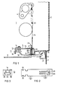
- FIG. 1 a section of a control cabinet or similar switchgear is shown in simplified form, which contains a low-voltage circuit breaker 1, which is shown in part.
- a control panel 2 a control shaft 3 with a crank arm 4 and a lower cross member 5 are shown in particular.
- the circuit breaker 1 rests in the control cabinet on a base plate 6 in a manner not shown in detail.
- a door 7 is provided for closing the installation space of the circuit breaker 1.
- the door 7 has a cutout 10 for the passage of the control panel 2 of the circuit breaker 1.
- a locking device 11 which consists of several parts, which will be described below.
- a locking lever 12 which is attached to the cross member 5 in a vertically pivotable manner.
- a bearing bracket 13 is used for this purpose, which is attached with its one leg 14 to the middle leg 15 of the cross member 5 by means of a conventional screw connection.
- the other leg 16 of the bearing bracket 13 is longer than the parallel leg 17 of the Cross member 5, whereby the leg 17 acts with its lower edge as a bearing surface for the pivoting movement of the locking lever 12.
- the locking lever 12 rests on the front side of the other leg 20 of the cross member 5 in the idle state.
- a door-side end part 18 of the locking lever 12 has, due to a design to be described later, the shape of a bracket which is able to overlap a locking lug 21 attached to the door 7, as shown in broken lines in FIG.
- the locking lever 12 is held by an opening spring 22 designed as a tension spring, the upper end of which is hooked into an opening 23 of the crank arm 4 located on the selector shaft 3.
- the opening spring 22 has an elongated end 24 with a hook-like end part 25 which is suspended in an opening 29 which is located in a widened end part 28 of an angled extension 26 of the locking lever 12.
- the cross member 5 is provided with a corresponding opening 27 which has a wider section for the passage of the end part 28 and a subsequent narrower section, as can be seen in particular in FIG.
- a closing spring 30 designed as a helical compression spring is arranged between the central part 15 of the cross member 5 and the locking lever 12.
- a support plate 31 is provided for the lower end of this spring.
- the opening spring 22 is stronger than the closing spring 30, in such a way that the force of the closing spring 30 in the position of the parts shown in FIG. 1 is overcome by the opening spring 22 and the locking lever 12 is thereby held in the rest position shown.
- the switching shaft 30 for closing the switching contacts of the circuit breaker 1 executes a pivoting movement in a clockwise direction, the holding force acting on the locking lever 12 is reduced, so that the closing spring 30 now comes into effect and the locking lever 12 is dotted in the dash-dot line shown closed position transferred.
- the bow-shaped front end part 18 of the locking lever 12 overlaps the locking lug 21 on the door 7.
- the locking lever 12 is a sheet metal part, which is shown in the extended state in FIG.
- recesses 31 are provided in a symmetrical arrangement at the end of the locking lever 12 provided for this purpose.
- the bearing lever 13 has an opening 33 in its leg 16, which has a narrower section 34 and a further section 35.
- the narrower section 34 corresponds to the width of the locking lever 12 in the region of the recesses 32, while the wider section 35 corresponds to the overall width of the locking lever 12.
- the locking lever 12 for attachment to the bearing bracket 13 can first be inserted into the wider part 35 of the opening 33 and then displaced in such a way that the recesses 32 reach the area of the material projections 36, which result from the transition between the wider section 35 to the narrower section 34 are formed.
- the position of the recess 33 in the leg 16 and the dimensioning of the leg 17 of the cross member 5 ensure that the locking lever remains in engagement with the projections 36 when the bearing bracket 13 in the position shown in FIG. 1 with the cross member 5 connected is.
- extension 26 is formed by a punch and a subsequent approximately right-angled bend.
- front bow-like end 18 of the locking lever 12 is formed by the punching process.
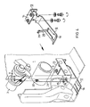
- FIG. 4 shows how the locking device can be attached to the circuit breaker 1.
- the locking lever 12 is inserted in the manner already described with its rear end into the opening of the bearing bracket 13 plugged in.
- This arrangement is mounted on the cross member 5 in such a way that the bearing bracket 13 rests on the central part 15 of the cross member 5 and the extension 26 passes through the opening 27 in the central part 15. Due to the slight displacement of the locking lever 12 during assembly, the widened end part 28 of the extension 26 passes over the narrower section of the opening 27, as a result of which the vertical pivoting path of the locking lever is restricted.
- the opening spring 22 can be hooked with its upper end into the opening 23 of the crank arm 4 and with its opposite hook-like end part 25 into the opening 29 at the end of the extension 26.
- the locking device is hereby functional, provided a locking lug 21 has been attached to the door (not shown in FIG. 4) according to FIG.
- the closing spring 30 is omitted, since the locking lever 12 already tries to assume the closed position according to the dash-dotted position in FIG. 1 due to gravity. This happens in particular when the opening spring 22 should break or a faulty or incorrectly selected opening spring is used.
- the locking device can be overcome by an authorized operator by using an auxiliary tool.
- a small opening 8 is made in the door 7, which can also be closed in a known manner by a cover slide.
- a tool inserted through the opening 8 abuts and raises the obliquely angled end part 18, as a result of which the locking lug 21 is released.
- a subsequent closing of the door 7 is easily possible due to the inclined position of the end part 18.
Landscapes
- Patch Boards (AREA)
- Coupling Device And Connection With Printed Circuit (AREA)
- Details Of Connecting Devices For Male And Female Coupling (AREA)
- Keying Circuit Devices (AREA)
- Relay Circuits (AREA)
- Coin-Freed Apparatuses For Hiring Articles (AREA)
- Details Of Television Scanning (AREA)
- Emergency Protection Circuit Devices (AREA)
Applications Claiming Priority (2)
| Application Number | Priority Date | Filing Date | Title |
|---|---|---|---|
| DE8805458U DE8805458U1 (de) | 1988-04-20 | 1988-04-20 | Schaltschrank mit einem Niederspannungs-Leistungsschalter |
| DE8805458U | 1988-04-20 |
Publications (3)
| Publication Number | Publication Date |
|---|---|
| EP0338969A2 true EP0338969A2 (fr) | 1989-10-25 |
| EP0338969A3 EP0338969A3 (fr) | 1991-04-03 |
| EP0338969B1 EP0338969B1 (fr) | 1994-10-26 |
Family
ID=6823343
Family Applications (1)
| Application Number | Title | Priority Date | Filing Date |
|---|---|---|---|
| EP89730100A Expired - Lifetime EP0338969B1 (fr) | 1988-04-20 | 1989-04-11 | Armoire de commutation avec un appareil interrupteur de basse tension |
Country Status (4)
| Country | Link |
|---|---|
| EP (1) | EP0338969B1 (fr) |
| AT (1) | ATE113406T1 (fr) |
| DE (2) | DE8805458U1 (fr) |
| NO (1) | NO174649C (fr) |
Families Citing this family (1)
| Publication number | Priority date | Publication date | Assignee | Title |
|---|---|---|---|---|
| DE102010025240A1 (de) * | 2010-06-26 | 2011-12-29 | Eaton Industries Gmbh | Verriegelungsvorrichtung für eine Schaltschranktür |
Family Cites Families (4)
| Publication number | Priority date | Publication date | Assignee | Title |
|---|---|---|---|---|
| DE1037549B (de) * | 1952-09-25 | 1958-08-28 | Siemens Ag | Abschaltbare Kraftsteckdose mit gegenseitiger Verriegelung zwischen Schalter und Steckdose |
| US3028459A (en) * | 1959-02-19 | 1962-04-03 | Fed Pacific Electric Co | Switch and enclosure therefor |
| US3194907A (en) * | 1963-06-28 | 1965-07-13 | Gen Electric | Interlock mechanism for an enclosed electric switch |
| US3534186A (en) * | 1969-08-06 | 1970-10-13 | Giddings & Lewis | Door interlock system for electrical control cabinets |
-
1988
- 1988-04-20 DE DE8805458U patent/DE8805458U1/de not_active Expired
-
1989
- 1989-04-11 AT AT89730100T patent/ATE113406T1/de not_active IP Right Cessation
- 1989-04-11 EP EP89730100A patent/EP0338969B1/fr not_active Expired - Lifetime
- 1989-04-11 DE DE58908548T patent/DE58908548D1/de not_active Expired - Fee Related
- 1989-04-20 NO NO891637A patent/NO174649C/no unknown
Also Published As
| Publication number | Publication date |
|---|---|
| NO891637D0 (no) | 1989-04-20 |
| DE8805458U1 (de) | 1989-08-17 |
| EP0338969A3 (fr) | 1991-04-03 |
| DE58908548D1 (de) | 1994-12-01 |
| NO174649B (no) | 1994-02-28 |
| EP0338969B1 (fr) | 1994-10-26 |
| ATE113406T1 (de) | 1994-11-15 |
| NO891637L (no) | 1989-10-23 |
| NO174649C (no) | 1994-06-08 |
Similar Documents
| Publication | Publication Date | Title |
|---|---|---|
| DE3336207C3 (de) | Elektrischer Schalter mit Anschlag des Steuerhebels bei Zusammenschweissen der Kontakte | |
| DE3885989T2 (de) | Gekapseltes Schaltbrett. | |
| EP2140521B1 (fr) | Commutateur d'installation comportant un dispositif de borne a ressort de rappel | |
| EP0226532B1 (fr) | Cellule de commutation électrique avec une commande de déplacement pour un appareil de commutation mobile | |
| DE3431983C2 (fr) | ||
| DE2600333B2 (de) | Rückstellbarer Selbstschalter | |
| DE3544667A1 (de) | Einschubrahmen mit einer schutzplatte fuer eine trennkontaktanordnung | |
| DE2914088C2 (de) | Sperrvorrichtung für einen von Hand betätigbaren Schalthebel | |
| EP0117396A1 (fr) | Interrupteur de sécurité avec moyen de verrouillage contre la fermeture non autorisée | |
| DE2507729B2 (de) | Sperrklinkenvorrichtung für eine Schublade, insbesondere Kassenschublade für eine Registrierkasse | |
| WO1996023338A2 (fr) | Dispositif pour influer sur un organe de translation d'un appareil de commutation | |
| DE2556520C2 (de) | Verriegelungsvorrichtung | |
| DE2419038A1 (de) | Elektrische schaltvorrichtung | |
| EP0109544A2 (fr) | Dispositif de verrouillage pour tiroir | |
| EP0338969B1 (fr) | Armoire de commutation avec un appareil interrupteur de basse tension | |
| DE10131636A1 (de) | Türverriegelungsvorrichtung, insbesondere für ein elektrisches Haushaltsgerät | |
| EP3045644A1 (fr) | Dispositif evitant la fermeture d'une porte | |
| DE69513329T2 (de) | Differential-Auslösevorrichtung | |
| EP1365089A2 (fr) | Dispositif de sécurité pour sorties de secours | |
| DE3425090C1 (de) | Verriegelungsvorrichtung mit wenigstens einem Riegel oder dgl. und mit einer Sperre fuer diesen Riegel | |
| DE2705330C2 (de) | Elektrischer Schalter, insbesondere Motorschutzschalter | |
| DE69301278T2 (de) | Verriegelungsvorrichtung für Lastschalter mit Klappdeckel | |
| DE2017596B2 (de) | Schaltschloss, insbesondere zur steuerung von elektrischen schaltgeraeten | |
| DE3880653T2 (de) | Schalter, insbesondere zur Verwendung als automatischer Schalter. | |
| DE19846219B4 (de) | Stromschalter |
Legal Events
| Date | Code | Title | Description |
|---|---|---|---|
| PUAI | Public reference made under article 153(3) epc to a published international application that has entered the european phase |
Free format text: ORIGINAL CODE: 0009012 |
|
| AK | Designated contracting states |
Kind code of ref document: A2 Designated state(s): AT BE CH DE FR GB IT LI NL SE |
|
| PUAL | Search report despatched |
Free format text: ORIGINAL CODE: 0009013 |
|
| 17P | Request for examination filed |
Effective date: 19901220 |
|
| AK | Designated contracting states |
Kind code of ref document: A3 Designated state(s): AT BE CH DE FR GB IT LI NL SE |
|
| 17Q | First examination report despatched |
Effective date: 19940202 |
|
| GRAA | (expected) grant |
Free format text: ORIGINAL CODE: 0009210 |
|
| AK | Designated contracting states |
Kind code of ref document: B1 Designated state(s): AT BE CH DE FR GB IT LI NL SE |
|
| REF | Corresponds to: |
Ref document number: 113406 Country of ref document: AT Date of ref document: 19941115 Kind code of ref document: T |
|
| REF | Corresponds to: |
Ref document number: 58908548 Country of ref document: DE Date of ref document: 19941201 |
|
| ITF | It: translation for a ep patent filed | ||
| GBT | Gb: translation of ep patent filed (gb section 77(6)(a)/1977) |
Effective date: 19941222 |
|
| ET | Fr: translation filed | ||
| PGFP | Annual fee paid to national office [announced via postgrant information from national office to epo] |
Ref country code: GB Payment date: 19950320 Year of fee payment: 7 |
|
| PGFP | Annual fee paid to national office [announced via postgrant information from national office to epo] |
Ref country code: NL Payment date: 19950817 Year of fee payment: 7 Ref country code: BE Payment date: 19950817 Year of fee payment: 7 |
|
| PLBE | No opposition filed within time limit |
Free format text: ORIGINAL CODE: 0009261 |
|
| STAA | Information on the status of an ep patent application or granted ep patent |
Free format text: STATUS: NO OPPOSITION FILED WITHIN TIME LIMIT |
|
| 26N | No opposition filed | ||
| PGFP | Annual fee paid to national office [announced via postgrant information from national office to epo] |
Ref country code: SE Payment date: 19960410 Year of fee payment: 8 |
|
| PG25 | Lapsed in a contracting state [announced via postgrant information from national office to epo] |
Ref country code: GB Effective date: 19960411 |
|
| PG25 | Lapsed in a contracting state [announced via postgrant information from national office to epo] |
Ref country code: BE Effective date: 19960430 |
|
| BERE | Be: lapsed |
Owner name: SIEMENS A.G. Effective date: 19960430 |
|
| PG25 | Lapsed in a contracting state [announced via postgrant information from national office to epo] |
Ref country code: NL Effective date: 19961101 |
|
| GBPC | Gb: european patent ceased through non-payment of renewal fee |
Effective date: 19960411 |
|
| NLV4 | Nl: lapsed or anulled due to non-payment of the annual fee |
Effective date: 19961101 |
|
| PGFP | Annual fee paid to national office [announced via postgrant information from national office to epo] |
Ref country code: AT Payment date: 19970326 Year of fee payment: 9 |
|
| PG25 | Lapsed in a contracting state [announced via postgrant information from national office to epo] |
Ref country code: SE Effective date: 19970412 |
|
| PGFP | Annual fee paid to national office [announced via postgrant information from national office to epo] |
Ref country code: CH Payment date: 19970715 Year of fee payment: 9 |
|
| EUG | Se: european patent has lapsed |
Ref document number: 89730100.8 |
|
| PG25 | Lapsed in a contracting state [announced via postgrant information from national office to epo] |
Ref country code: AT Free format text: LAPSE BECAUSE OF NON-PAYMENT OF DUE FEES Effective date: 19980411 |
|
| PG25 | Lapsed in a contracting state [announced via postgrant information from national office to epo] |
Ref country code: LI Free format text: LAPSE BECAUSE OF NON-PAYMENT OF DUE FEES Effective date: 19980430 Ref country code: CH Free format text: LAPSE BECAUSE OF NON-PAYMENT OF DUE FEES Effective date: 19980430 |
|
| REG | Reference to a national code |
Ref country code: CH Ref legal event code: PL |
|
| PGFP | Annual fee paid to national office [announced via postgrant information from national office to epo] |
Ref country code: FR Payment date: 20010420 Year of fee payment: 13 |
|
| PGFP | Annual fee paid to national office [announced via postgrant information from national office to epo] |
Ref country code: DE Payment date: 20010620 Year of fee payment: 13 |
|
| PG25 | Lapsed in a contracting state [announced via postgrant information from national office to epo] |
Ref country code: DE Free format text: LAPSE BECAUSE OF NON-PAYMENT OF DUE FEES Effective date: 20021101 |
|
| PG25 | Lapsed in a contracting state [announced via postgrant information from national office to epo] |
Ref country code: FR Free format text: LAPSE BECAUSE OF NON-PAYMENT OF DUE FEES Effective date: 20021231 |
|
| REG | Reference to a national code |
Ref country code: FR Ref legal event code: ST |
|
| PG25 | Lapsed in a contracting state [announced via postgrant information from national office to epo] |
Ref country code: IT Free format text: LAPSE BECAUSE OF NON-PAYMENT OF DUE FEES Effective date: 20050411 |