EP0338873B1 - Courroie doublement striée et son procédé de fabrication - Google Patents
Courroie doublement striée et son procédé de fabrication Download PDFInfo
- Publication number
- EP0338873B1 EP0338873B1 EP89400771A EP89400771A EP0338873B1 EP 0338873 B1 EP0338873 B1 EP 0338873B1 EP 89400771 A EP89400771 A EP 89400771A EP 89400771 A EP89400771 A EP 89400771A EP 0338873 B1 EP0338873 B1 EP 0338873B1
- Authority
- EP
- European Patent Office
- Prior art keywords
- profile
- blank
- belt
- reference face
- ribs
- Prior art date
- Legal status (The legal status is an assumption and is not a legal conclusion. Google has not performed a legal analysis and makes no representation as to the accuracy of the status listed.)
- Expired - Lifetime
Links
- 238000000034 method Methods 0.000 title claims description 20
- 238000004073 vulcanization Methods 0.000 claims description 13
- 238000004519 manufacturing process Methods 0.000 claims description 12
- 238000005520 cutting process Methods 0.000 claims description 10
- 238000000227 grinding Methods 0.000 claims description 9
- 239000004744 fabric Substances 0.000 claims description 8
- 238000003754 machining Methods 0.000 claims description 7
- 238000000465 moulding Methods 0.000 claims description 7
- 238000007493 shaping process Methods 0.000 claims description 5
- 238000001816 cooling Methods 0.000 claims description 3
- 229920001971 elastomer Polymers 0.000 description 7
- 239000000835 fiber Substances 0.000 description 5
- 239000011159 matrix material Substances 0.000 description 5
- 239000005060 rubber Substances 0.000 description 4
- 239000000806 elastomer Substances 0.000 description 3
- 240000008042 Zea mays Species 0.000 description 2
- 230000015572 biosynthetic process Effects 0.000 description 2
- 238000010586 diagram Methods 0.000 description 2
- 238000009434 installation Methods 0.000 description 2
- 229920000728 polyester Polymers 0.000 description 2
- 230000002787 reinforcement Effects 0.000 description 2
- UDHXJZHVNHGCEC-UHFFFAOYSA-N Chlorophacinone Chemical compound C1=CC(Cl)=CC=C1C(C=1C=CC=CC=1)C(=O)C1C(=O)C2=CC=CC=C2C1=O UDHXJZHVNHGCEC-UHFFFAOYSA-N 0.000 description 1
- 244000043261 Hevea brasiliensis Species 0.000 description 1
- 239000004760 aramid Substances 0.000 description 1
- 229920003235 aromatic polyamide Polymers 0.000 description 1
- 230000005540 biological transmission Effects 0.000 description 1
- 239000013536 elastomeric material Substances 0.000 description 1
- 229940082150 encore Drugs 0.000 description 1
- 230000012447 hatching Effects 0.000 description 1
- 238000009776 industrial production Methods 0.000 description 1
- 239000000463 material Substances 0.000 description 1
- 239000002184 metal Substances 0.000 description 1
- 238000003801 milling Methods 0.000 description 1
- 229920003052 natural elastomer Polymers 0.000 description 1
- 229920001194 natural rubber Polymers 0.000 description 1
- 229920001084 poly(chloroprene) Polymers 0.000 description 1
- 238000003825 pressing Methods 0.000 description 1
- 238000004804 winding Methods 0.000 description 1
Images

Classifications
-
- F—MECHANICAL ENGINEERING; LIGHTING; HEATING; WEAPONS; BLASTING
- F16—ENGINEERING ELEMENTS AND UNITS; GENERAL MEASURES FOR PRODUCING AND MAINTAINING EFFECTIVE FUNCTIONING OF MACHINES OR INSTALLATIONS; THERMAL INSULATION IN GENERAL
- F16G—BELTS, CABLES, OR ROPES, PREDOMINANTLY USED FOR DRIVING PURPOSES; CHAINS; FITTINGS PREDOMINANTLY USED THEREFOR
- F16G5/00—V-belts, i.e. belts of tapered cross-section
- F16G5/20—V-belts, i.e. belts of tapered cross-section with a contact surface of special shape, e.g. toothed
-
- B—PERFORMING OPERATIONS; TRANSPORTING
- B26—HAND CUTTING TOOLS; CUTTING; SEVERING
- B26D—CUTTING; DETAILS COMMON TO MACHINES FOR PERFORATING, PUNCHING, CUTTING-OUT, STAMPING-OUT OR SEVERING
- B26D3/00—Cutting work characterised by the nature of the cut made; Apparatus therefor
- B26D3/06—Grooving involving removal of material from the surface of the work
-
- B—PERFORMING OPERATIONS; TRANSPORTING
- B29—WORKING OF PLASTICS; WORKING OF SUBSTANCES IN A PLASTIC STATE IN GENERAL
- B29D—PRODUCING PARTICULAR ARTICLES FROM PLASTICS OR FROM SUBSTANCES IN A PLASTIC STATE
- B29D29/00—Producing belts or bands
- B29D29/10—Driving belts having wedge-shaped cross-section
- B29D29/103—Multi-ribbed driving belts
Definitions
- the subject of the invention is a doubly ribbed belt and its manufacturing process.
- ribbed belts which, in the definition given for example by the French standard AFNOR R 15 506, are endless belts comprising a frame intended to resist traction and whose contact surface with a pulley has longitudinal ribs at a given profile.
- Such belts relatively more flexible than the usual V-belts for power transmission, can be wound on pulleys of small diameter and, given the fact that they can be used for high rotational speeds, they find a particularly interesting application in the automotive field without, of course, that this indication has any limiting nature whatsoever.
- the problem is solved by a method of manufacturing a ribbed belt on its internal surface and its back surface along longitudinal ribs capable of cooperating with the grooves of the pulleys that the belt is intended to equip, from a formed blank.
- the method according to the invention can be carried out according to different modes.
- the method is characterized in that during the shaping of the blank in a first mold to produce the profile of ribs formed first, the part intended to be shaped to the profile formed second is not vulcanized and in that this operation is followed, after definition of a reference face of the blank by molding or by cutting, by turning the blank which is then shaped to the profile formed second by a process analogous to that obtaining the profile formed first.
- the invention is also characterized in that after shaping the blank according to the profile of ribs formed first, the shaped and vulcanized blank is turned over, and in that after having provided a reference face, the rib profile formed second from said reference face by machining, advantageously grinding or cutting.
- the invention also provides a method characterized in that after having completely vulcanized the blank in a mold to obtain a smooth tubular shape, and after cooling, it is put in place on a machining machine by grinding or cutting to produce the first profile of longitudinal ribs on its first surface, then after creation of a reference face, machining by grinding or cutting of the second profile of ribs after turning the vulcanized form, machined on its first surface .
- the profiles of ribs on both surfaces of the belt can be the same or different.
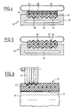
- FIGS. 1 and 2 diagrammatically each show a belt of doubly striated elastomeric material 10 and 11, respectively, comprising, where appropriate, fabrics in one or more plies and in which the reinforcement intended to resist traction and which defines the primitive zone is designated by the reference 12 or 13, respectively, said reinforcement being made of cables polyester fibers or aromatic polyamide fibers or the like.
- the belt 10 has on its surface 14 ribs 151, 152, 153, etc., with a truncated cross section and which are of the type of those known in the French standard mentioned above under the name of profile "K" but which can, of course, be of triangular or truncated cross section as defined by the references H, J, L or M of the aforementioned standard.
- the belt 10 On its other surface 16 or back, the belt 10 also has ribs 171, 172, 173, etc., with the same profile and at the same pitch as that of the internal surface, the ribs 15 and 17 being in mirror symmetry with respect to in the mean plane of the belt, which is here that of the frame 12.
- the external surface or back 18 of the belt 11 has a structure identical to that described above for the belt 10 but its internal surface is provided with ribs 19 of substantially triangular cross section, of the type those defined by the standard already cited under the profile name "J" but which can, of course, be of triangular or truncated cross section as defined by the references H, K, L or M of the aforementioned standard.
- the pitch of the ribs 19 of the internal surface is substantially half that of the ribs of the external surface or back 18.
- a belt like 10 or 11, advantageously finds application, for example, in the installation of the engine compartment of an automobile, FIG. 3, where a driving pulley 20 drives driven pulleys 21 and 22 with which the internal surface of the belt and also drives a pulley 23 which cooperates with the back of the belt, the latter being kept under appropriate tension by means of a tensioner 24 also acting on the back of the belt.
- the invention provides a method of manufacturing the belt according to which after obtaining a first profile on one of the operating surfaces of the belt, that is to say one of the contact surfaces with the grooves of the pulleys which it is intended to equip, a reference face is defined for the precise positioning of the second profile on the other surface of the belt which is then produced by the same process or a process different from that which has made it possible to get the first profile.
- a blank 30, FIG. 4 is first prepared in the usual manner by winding layers of rubber, fabrics and cords 31 on a cylindrical mandrel.
- the blank is then transferred to a molding device, shown diagrammatically at 32, and which comprises a metal matrix 33 shaped in its operating part along teeth 34 intended to produce the first profile of ribs 39 of the belt and also shaped according to a wall 35 intended to provide a reference face, the set of teeth and said wall being machined with great precision, of the order of a hundredth of mm.
- the matrix 33 which comprises means for adjusting the temperature shown diagrammatically at 36, is associated with a member 37 for applying pressure, of the "air bag" type capable of exerting during the entire vulcanization operation a pressure which can be of the order of 20 bars.
- the blank 30 is cooled so as to avoid shrinkage phenomena as much as possible.
- the blank is then turned over, that is to say brought into a condition where the unvulcanized part 38 is inside the blank while the ribs 39 of the first profile are outside, and said blank turned over is then transferred either to the same mold 32 used to form the first rib profile, if it is desired that the belt have the same profile on its two internal and back surfaces, or to a mold machined according to a profile different if you want to obtain a belt of the type shown in Figure 2.
- the second profile is produced during a vulcanization process similar to that used for the formation of the first, the precise positioning of the two rib profiles relative to the the other being obtained using the surface defined by the reference wall 35 of the matrix 33 of the mold 32.
- the ribs of one and the other operating surfaces of the belt are produced both by molding and machining.
- the blank 30 consisting of the layers of gum, fabrics and cables 31 is subjected to a vulcanization treatment in a mold 32, that is to say comprising a matrix machined in correspondence of a first profile of ribs, but the vulcanization operation is carried out here so as to interest the entire blank, so that, after vulcanization, a fully vulcanized tubular shape is obtained, the internal surface of which has the longitudinal ribs 39.
- Said tubular shape is then inverted to pass the ribs 39 from the inside to the outside then it is placed on the rotary drum of a grinding or milling cutter machine.
- the precise positioning of the second profile, cut or ground in the tubular shape is defined using the reference face obtained during the molding of the previous phase by the wall 35 of the mold 33 or by a cut of said tubular shape with a reference dimension which can be precisely defined on the machine tool.
- the blank 30 consisting of the layers of gum, fabrics and cables is first subjected to a vulcanization treatment without shaping to provide a smooth tube on its external surfaces. and internal.
- the smooth tube on the rotary mandrel 40, FIG. 6, of a machine tool for grinding or cutting with a rotary cutter 41 is formed.
- the tubular shape 43 is turned over to bring the ribs 42 inside said shape and the smooth cylindrical surface 44 outside.
- a second machining, by grinding or cutting, established from the reference face then makes it possible to obtain the desired doubly ribbed belt.
- the manufacturing process by machining is of particularly advantageous application for elastomers of relatively high hardness, such as polychloroprenes, preferably with lower hardness elastomers such as natural rubbers or the like.
- the method according to the invention is of particularly advantageous application in the case of fiber gums, that is to say of elastomeric materials loaded with oriented fibers, the arrangement of which can be chosen symmetrically. or not on both sides of the cables and fabrics ensuring the transverse stiffness of the belt.
Landscapes
- Engineering & Computer Science (AREA)
- Mechanical Engineering (AREA)
- General Engineering & Computer Science (AREA)
- Life Sciences & Earth Sciences (AREA)
- Forests & Forestry (AREA)
Applications Claiming Priority (2)
| Application Number | Priority Date | Filing Date | Title |
|---|---|---|---|
| FR8805278 | 1988-04-21 | ||
| FR8805278A FR2630515B1 (fr) | 1988-04-21 | 1988-04-21 | Courroie doublement striee et son procede de fabrication |
Publications (2)
| Publication Number | Publication Date |
|---|---|
| EP0338873A1 EP0338873A1 (fr) | 1989-10-25 |
| EP0338873B1 true EP0338873B1 (fr) | 1992-11-25 |
Family
ID=9365524
Family Applications (1)
| Application Number | Title | Priority Date | Filing Date |
|---|---|---|---|
| EP89400771A Expired - Lifetime EP0338873B1 (fr) | 1988-04-21 | 1989-03-20 | Courroie doublement striée et son procédé de fabrication |
Country Status (4)
| Country | Link |
|---|---|
| EP (1) | EP0338873B1 (es) |
| DE (2) | DE338873T1 (es) |
| ES (1) | ES2012309T3 (es) |
| FR (1) | FR2630515B1 (es) |
Families Citing this family (3)
| Publication number | Priority date | Publication date | Assignee | Title |
|---|---|---|---|---|
| EP0642886B1 (en) * | 1993-09-09 | 2000-02-16 | Mitsuboshi Belting Ltd. | Apparatus and method for forming ribs on a belt/belt sleeve |
| JP3485801B2 (ja) * | 1998-05-29 | 2004-01-13 | 三ツ星ベルト株式会社 | ダブルリブベルトの製造方法 |
| JP2000240732A (ja) | 1999-02-24 | 2000-09-05 | Bando Chem Ind Ltd | Vリブドベルト及びその製造方法 |
Family Cites Families (8)
| Publication number | Priority date | Publication date | Assignee | Title |
|---|---|---|---|---|
| US3839116A (en) * | 1973-09-10 | 1974-10-01 | Dayco Corp | Method of making endless power transmission belt having a plurality of longitudinally extending ribs |
| DE2926841A1 (de) * | 1979-07-03 | 1981-01-22 | Siemens Ag | Elektronenbeschleuniger |
| US4253836A (en) * | 1979-09-14 | 1981-03-03 | Dayco Corporation | Mobius belt and method of making the same |
| DE3033015C2 (de) * | 1980-09-02 | 1983-01-20 | Präzisions-Gummifabrik Georg März KG, 8060 Dachau | Antriebsriemen mit Vierkantprofil aus Gummi oder gummiartigem Werkstoff sowie Verfahren und Vorrichtung zu seiner Herstellung |
| JPS60159039A (ja) * | 1984-01-30 | 1985-08-20 | Mitsuboshi Belting Ltd | ダブルタイミングベルトの製造方法 |
| DE3524583A1 (de) * | 1985-07-09 | 1987-01-15 | Bando Chemical Ind | Schneidvorrichtung, insbesondere in der verwendung bei der herstellung von treibriemen |
| US4662863A (en) * | 1985-08-30 | 1987-05-05 | Uniroyal Power Transmission Co., Inc. | Double-acting power transmission belt |
| JPS62135353A (ja) * | 1985-12-10 | 1987-06-18 | Mitsuboshi Belting Ltd | ダブルタイミングベルトの製造方法 |
-
1988
- 1988-04-21 FR FR8805278A patent/FR2630515B1/fr not_active Expired - Fee Related
-
1989
- 1989-03-20 ES ES198989400771T patent/ES2012309T3/es not_active Expired - Lifetime
- 1989-03-20 EP EP89400771A patent/EP0338873B1/fr not_active Expired - Lifetime
- 1989-03-20 DE DE198989400771T patent/DE338873T1/de active Pending
- 1989-03-20 DE DE8989400771T patent/DE68903594T2/de not_active Expired - Fee Related
Also Published As
| Publication number | Publication date |
|---|---|
| ES2012309A4 (es) | 1990-03-16 |
| EP0338873A1 (fr) | 1989-10-25 |
| FR2630515A1 (fr) | 1989-10-27 |
| DE68903594D1 (de) | 1993-01-07 |
| DE338873T1 (de) | 1990-04-12 |
| ES2012309T3 (es) | 1993-05-01 |
| DE68903594T2 (de) | 1993-04-01 |
| FR2630515B1 (fr) | 1991-09-27 |
Similar Documents
| Publication | Publication Date | Title |
|---|---|---|
| EP0829658B1 (fr) | Procédé de fabrication d'une courroie de transmission et courroie obtenue par ce procédé | |
| FR2479086A1 (fr) | Bande de roulement preformee et procede de confection d'un pneu muni d'une telle bande de roulement | |
| EP1115587A1 (fr) | Armature de sommet pour pneumatique radial | |
| EP0281432B2 (fr) | Courroie sans fin de transmission de puissance | |
| EP0338873B1 (fr) | Courroie doublement striée et son procédé de fabrication | |
| WO2002083434A1 (fr) | Pneumatique avec structure de renfort | |
| EP0332495B1 (fr) | Procédé de fabrication de pièces de carrosserie d'automobile, notamment d'aileron ou becquet arrière, et pièces obtenues par mise en oeuvre de ce procédé | |
| WO2003055667A1 (fr) | Methode de pose de fils de structure de renfort pour pneumatique | |
| FR2627725A1 (fr) | Pneumatique a corps principal, forme de deux demi-corps circulaires | |
| FR2886202A1 (fr) | Procede de fabrication d'une ame en resine synthetique | |
| EP1254034B1 (fr) | Bourrelet pour pneumatique a mobilite etendue | |
| EP0721854A1 (fr) | Dispositif de roulage à plat pour véhicule automobile et son procédé de fabrication | |
| WO2003055701A1 (fr) | Pneumatique avec structure de renfort formant des boucles internes et externes | |
| FR2793460A1 (fr) | Composant decoratif et procede de fabrication d'un tel composant decoratif et procede de fabrication d'une piece d'habillage interieur d'un vehicule, par exemple, un panneau de portiere, utilisant ledit composant decoratif | |
| CA2126658C (fr) | Procede et dispositif d'assemblage d'une carcasse de pneumatique et d'une bande de roulement annulaire etiree par centrifugation | |
| LU85964A1 (fr) | Bandage pneumatique et son procede de fabrication | |
| EP0389307B1 (fr) | Chambre à air, notamment pour véhicule du type bicyclette ou cyclomoteur | |
| FR2725933A1 (fr) | Eventation de moules | |
| FR2778369A1 (fr) | Pneumatique a armature de carcasse a deux rigidites | |
| EP1034908A1 (fr) | Element moulant pour moule de bande de roulement de pneumatique | |
| EP0976519A1 (fr) | Procédé d'ancrage d'une masse thermoplastique et pièce obtenue par mise en oeuvre de ce procédé | |
| EP0885133A1 (fr) | Pneu radial comportant une nappe carcasse dont la soudure par recouvrement est pourvue de decoupes | |
| EP0968802B1 (fr) | Moule et élément moulant pour mouler une incision dans un article de gomme | |
| EP0118745A2 (fr) | Nappe de renfort pour enveloppe de pneumatique constituée au moins en partie par un tissu avec un corps tridimensionnel; enveloppes de pneumatiques comportant au moins une telle nappe; procédé permettant d'obtenir ces enveloppes | |
| WO2019025726A1 (fr) | Ensemble stabilisateur pour vehicule |
Legal Events
| Date | Code | Title | Description |
|---|---|---|---|
| PUAI | Public reference made under article 153(3) epc to a published international application that has entered the european phase |
Free format text: ORIGINAL CODE: 0009012 |
|
| AK | Designated contracting states |
Kind code of ref document: A1 Designated state(s): BE DE ES GB IT LU NL SE |
|
| GBC | Gb: translation of claims filed (gb section 78(7)/1977) | ||
| TCNL | Nl: translation of patent claims filed | ||
| DET | De: translation of patent claims | ||
| 17P | Request for examination filed |
Effective date: 19900329 |
|
| 17Q | First examination report despatched |
Effective date: 19910612 |
|
| GRAA | (expected) grant |
Free format text: ORIGINAL CODE: 0009210 |
|
| AK | Designated contracting states |
Kind code of ref document: B1 Designated state(s): BE DE ES GB IT LU NL SE |
|
| GBT | Gb: translation of ep patent filed (gb section 77(6)(a)/1977) | ||
| REF | Corresponds to: |
Ref document number: 68903594 Country of ref document: DE Date of ref document: 19930107 |
|
| ITF | It: translation for a ep patent filed | ||
| REG | Reference to a national code |
Ref country code: ES Ref legal event code: FG2A Ref document number: 2012309 Country of ref document: ES Kind code of ref document: T3 |
|
| PLBE | No opposition filed within time limit |
Free format text: ORIGINAL CODE: 0009261 |
|
| STAA | Information on the status of an ep patent application or granted ep patent |
Free format text: STATUS: NO OPPOSITION FILED WITHIN TIME LIMIT |
|
| 26N | No opposition filed | ||
| EPTA | Lu: last paid annual fee | ||
| EAL | Se: european patent in force in sweden |
Ref document number: 89400771.5 |
|
| REG | Reference to a national code |
Ref country code: GB Ref legal event code: IF02 |
|
| PGFP | Annual fee paid to national office [announced via postgrant information from national office to epo] |
Ref country code: SE Payment date: 20030221 Year of fee payment: 15 |
|
| PGFP | Annual fee paid to national office [announced via postgrant information from national office to epo] |
Ref country code: LU Payment date: 20030227 Year of fee payment: 15 |
|
| PGFP | Annual fee paid to national office [announced via postgrant information from national office to epo] |
Ref country code: GB Payment date: 20030303 Year of fee payment: 15 |
|
| PGFP | Annual fee paid to national office [announced via postgrant information from national office to epo] |
Ref country code: BE Payment date: 20030310 Year of fee payment: 15 |
|
| PGFP | Annual fee paid to national office [announced via postgrant information from national office to epo] |
Ref country code: ES Payment date: 20030320 Year of fee payment: 15 |
|
| PGFP | Annual fee paid to national office [announced via postgrant information from national office to epo] |
Ref country code: DE Payment date: 20030327 Year of fee payment: 15 |
|
| PGFP | Annual fee paid to national office [announced via postgrant information from national office to epo] |
Ref country code: NL Payment date: 20030328 Year of fee payment: 15 |
|
| PG25 | Lapsed in a contracting state [announced via postgrant information from national office to epo] |
Ref country code: LU Free format text: LAPSE BECAUSE OF NON-PAYMENT OF DUE FEES Effective date: 20040320 Ref country code: GB Free format text: LAPSE BECAUSE OF NON-PAYMENT OF DUE FEES Effective date: 20040320 |
|
| PG25 | Lapsed in a contracting state [announced via postgrant information from national office to epo] |
Ref country code: SE Free format text: LAPSE BECAUSE OF NON-PAYMENT OF DUE FEES Effective date: 20040321 |
|
| PG25 | Lapsed in a contracting state [announced via postgrant information from national office to epo] |
Ref country code: ES Free format text: LAPSE BECAUSE OF NON-PAYMENT OF DUE FEES Effective date: 20040322 |
|
| PG25 | Lapsed in a contracting state [announced via postgrant information from national office to epo] |
Ref country code: BE Free format text: LAPSE BECAUSE OF NON-PAYMENT OF DUE FEES Effective date: 20040331 |
|
| BERE | Be: lapsed |
Owner name: *HUTCHINSON Effective date: 20040331 |
|
| PG25 | Lapsed in a contracting state [announced via postgrant information from national office to epo] |
Ref country code: NL Free format text: LAPSE BECAUSE OF NON-PAYMENT OF DUE FEES Effective date: 20041001 Ref country code: DE Free format text: LAPSE BECAUSE OF NON-PAYMENT OF DUE FEES Effective date: 20041001 |
|
| EUG | Se: european patent has lapsed | ||
| GBPC | Gb: european patent ceased through non-payment of renewal fee |
Effective date: 20040320 |
|
| NLV4 | Nl: lapsed or anulled due to non-payment of the annual fee |
Effective date: 20041001 |
|
| PG25 | Lapsed in a contracting state [announced via postgrant information from national office to epo] |
Ref country code: IT Free format text: LAPSE BECAUSE OF NON-PAYMENT OF DUE FEES Effective date: 20050320 |
|
| REG | Reference to a national code |
Ref country code: ES Ref legal event code: FD2A Effective date: 20040322 |