EP0338613B1 - Sperrvorrichtung für einen Zahnradaufzug - Google Patents
Sperrvorrichtung für einen Zahnradaufzug Download PDFInfo
- Publication number
- EP0338613B1 EP0338613B1 EP89200894A EP89200894A EP0338613B1 EP 0338613 B1 EP0338613 B1 EP 0338613B1 EP 89200894 A EP89200894 A EP 89200894A EP 89200894 A EP89200894 A EP 89200894A EP 0338613 B1 EP0338613 B1 EP 0338613B1
- Authority
- EP
- European Patent Office
- Prior art keywords
- blocking member
- shaft
- engagement
- abutment
- friction member
- Prior art date
- Legal status (The legal status is an assumption and is not a legal conclusion. Google has not performed a legal analysis and makes no representation as to the accuracy of the status listed.)
- Expired - Lifetime
Links
- 230000000903 blocking effect Effects 0.000 claims description 37
- 230000002093 peripheral effect Effects 0.000 claims description 2
- 241001131688 Coracias garrulus Species 0.000 description 6
- 230000000295 complement effect Effects 0.000 description 1
- 230000000694 effects Effects 0.000 description 1
- 230000013011 mating Effects 0.000 description 1
- 239000000725 suspension Substances 0.000 description 1
Images

Classifications
-
- B—PERFORMING OPERATIONS; TRANSPORTING
- B66—HOISTING; LIFTING; HAULING
- B66B—ELEVATORS; ESCALATORS OR MOVING WALKWAYS
- B66B5/00—Applications of checking, fault-correcting, or safety devices in elevators
- B66B5/02—Applications of checking, fault-correcting, or safety devices in elevators responsive to abnormal operating conditions
- B66B5/16—Braking or catch devices operating between cars, cages, or skips and fixed guide elements or surfaces in hoistway or well
- B66B5/18—Braking or catch devices operating between cars, cages, or skips and fixed guide elements or surfaces in hoistway or well and applying frictional retarding forces
Definitions
- the present invention relates to a catch apparatus for a rack lift, with a tooth wheel engaging the rack and unrotatably mounted on a shaft, which also carries two friction members, which are spring tensioned towards each other for mutual frictional engagement, and of which one is unrotatably carried by the shaft, and the other one is glidingly supported on the shaft but normally co-rotating through the frictional engagement, an inertia blocking mechanism, being arranged to stop the other friction member at exceeding of a limit velocity of the shaft, for thereby braking the shaft through the frictional engagement.
- a catch apparatus for a driven shaft comprises a brake disc and a cam disc for a runner roll which is pressable against the cam disc by means of a release spring and has a catch lever associated therewith, which engages the cam disc in response to an overspeed.
- This catch apparatus In order to make this catch apparatus to respond to both directions of rotation two tooth rings with opposite catch action of the teeth as well as a basic body with a catch bolt for oppositely directed catch levers are arranged on the shaft. For simultaneous engagement and disengagement of the catch levers a disengagement pin and an engagement bolt are supported in the basic body.
- the object of the present invention is to effect a safer and more reliable braking of the lift than has hithertoo been possible with an apparatus of the kind defined by way introduction above.
- the blocking mechanism includes a blocking member which is suspended for pendulum movement in a plane extending transversely to the shaft in order to be clamped, when the limit velocity is exceeded, between a fixed abutment and an abutment carried by the other friction member.
- the apparatus according to the invention also differs from the subject matter of EP-A 279 144.
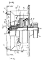
- FIG. 1 partly in section shows a catch apparatus according to the invention in the direction of arrows I-I in Fig. 2, and Fig. 2 illustrates the catch apparatus in the direction of arrows II-II in Fig. 1.
- the catch apparatus has a tooth wheel 4 in engagement with the rack, not shown, and non-rotatably connected to a shaft 4.
- the shaft 4 is journalled at 6 in a base plate 8 which is fixedly connected to the lift cage and intended to be vertically mounted.
- a yoke 10 is mounted in the same horizontal plane as the shaft 4.
- the yoke 10 has a central opening for the shaft 4 and elements connected thereto, which will be described more closely below.
- the yoke 8 carries a casing 12 for the catch apparatus. More particularly the casing 12 is attached to the yoke 8 by means of screwed joints 14.
- the shaft 4 non-rotatably carries a wheel 16 with a conically extending peripheral surface.
- the wheel 16 is recessed in a bowl 18 normally rotating with the shaft 4.
- the bowl 18 has a conical inner wall mating with the conical periphery of the wheel 16. Between the conical surfaces of the wheel 16 and the bowl 18 a friction lining is arranged.
- the bowl 18 is seated on the shaft 4 via a slide bearing 20.
- Above the bowl 18 the shaft 4 carries a sleeve 22 which is journalled in the opening of the yoke 8 by means of bearings 24. Below the yoke 10 the sleeve 22 is widening into a cup shaped housing 26 for a disc spring package 28.
- the sleeve 22 is kept in place on the end of the shaft 4 by means of an end plate 30, which is attached to the shaft 4 by means of four screws 32. More particularly, a shoulder 34 of the plate 30 presses against the end of the sleeve 22 via a washer 36.
- the bowl 18 has two externally profiled shoulders 38 and 40.
- the shoulder 38 has a hexagonal shape, as appears from the plane view in Fig. 2.
- the shoulder 40 has a saw tooth shaped profile with six teeth, as likewise appears from the plane view of Fig. 2. In the manner shown each of the teeth are arranged in front of its respective one of the plane sides of the hexagonal shoulder 38. Each tooth has furthermore a tooth shoulder 42 facing in the rotational direction.
- An oval pendulum member 42 is pivotally suspended at one of its ends on a bolt 46 fixedly connected to the plate 8.
- the bolt 46 is not visible in Fig. 1.
- the oval pendulum member 44 in front of each leg of the yoke 8 has a projecting abutment 48 and 50, respectively.
- the abutment 48 has such a length that the longitudinal axis of the pendulum member 44 extends essentially perpendicularly to the plane of the yoke 8 when the abutment 48 engages the adjacent leg of the yoke 8.
- the abutment 50 is shorter than the abutment 48 and carries a pressure spring 52 which is tensioned between the side of the pendulum member 44 and the adjacent leg of the yoke 8.
- the pendulum 44 pivotally carries a crescent shaped blocking member 54.
- the blocking member 54 is not visible in Fig. 1, but is carried behind the pendulum 44 so that it is located in the plane of the tooth profile 40.
- the blocking member 54 has a hook end 56 shaped for engagement with the tooth shoulder 42 and an opposite end 58.
- the blocking member 54 On its inside facing away from the pendulum 44, in the vicinity of the end 58, the blocking member 54 carries a roller 60 in the same plane as the hexagonal profile 38.
- the roller 60 is resiliently pressed into light engagement with the circumference of the hexagonal profile 38 by means of a draw spring 62 acting between the pendelum 44 and the blocking member 54.
- the tension of the draw spring 62 is settable by means of a screw- and nut arrangement 64.
- the plate 8 carries a switch 66 connected in the drive circuit of the lift and having an operating element 68 which breaks the drive circuit at actuation by a shoulder 70 located on the blocking member 54, in a way to be described more closely below.
- a plate 72 with a V-shaped cut 74 is located in front of the adjacent end 58 of the blocking member 54, said end 58 having a pointed shape complementary to the cut 74.
- the described catch apparatus operates as follows.
- the above-mentioned limit velocity at which the catch device shall start work is determined by the tension of the spring 62.
- the braking time at first hand is decided by the spring force of the spring package 28 by means of which the bowl 18 is pressed against the wheel 16.
- the invention at first hand consists in the rocking suspension of the blocking member 54 by means of the pendelum 44, which at catching makes possible controlled introduction into the cut 74 and thereby an always fixed locking position for the blocking member 54. As a result also a safe operation of the switch is always obtained.
- the mentioned advantages have not been obtained in prior apparatus of similar kind where the catch element is fixedly mounted.
Landscapes
- Engineering & Computer Science (AREA)
- Mechanical Engineering (AREA)
- Braking Arrangements (AREA)
- Warehouses Or Storage Devices (AREA)
- Load-Engaging Elements For Cranes (AREA)
- Transmission Devices (AREA)
- Automatic Cycles, And Cycles In General (AREA)
Claims (8)
- Fangvorrichtung für eine Zahnantrieb-Hubvorrichtung, mit einem Zahnrad (2), das in den Zahnantrieb eingreift und drehfest auf einer Welle (4) montiert ist, welche auch ein erstes und zweites Reibungsglied (16, 18) trägt, die zum gegenseitigen Reibungseingriff durch Federkraft (28) aufeinander zu vorgespannt sind und von denen das erste Reibungsglied (16) drehfest durch die Welle (4) gehalten und das zweite Reibungsglied (18) auf der Welle gleitend gelagert (20) ist, sich jedoch normalerweise durch den Reibungseingriff mit dieser dreht, mit einer Trägheitsblockiervorrichtung (38, 74), die vorgesehen ist, das zweite Reibungsglied (18) beim Überschreiten einer Grenzgeschwindigkeit der Welle (4) anzuhalten, um dadurch die Welle durch den Reibungseingriff abzubremsen, wobei die Blockiervorrichtung ein Blockierelement (54) enthält, das zur Pendelbewegung in einer quer zur Welle (4) verlaufenden Ebene aufgehängt (44, 46) ist, um zwischen einem ortsfesten Lager (74) und einem vom zweiten Reibungsglied (18) getragenen Lager (42) eingeklemmt zu werden, wenn die Grenzgeschwindigkeit überschritten wird.
- Fangvorrichtung nach Anspruch 1, dadurch gekennzeichnet, daß das ortsfeste Lager einen Ausschnitt hat, in welchem eine Nase (58) des schwenkbar aufgehängten Blockierelements (54) vorgesehen ist, um beim Einklemmen zwischen den zwei Lagern (42, 74) geführt zu werden.
- Fangvorrichtung nach Anspruch 2, dadurch gekennzeichnet, daß im Ausschnitt (74) ein Schalter (66) innerhalb des Antriebsschaltkreises der Hubvorrichtung vorgesehen ist, der durch das schwenkbar aufgehängte Blockierelement (54) beim Einführen desselben in den Ausschnitt (74) betätigbar ist.
- Fangvorrichtung nach einem der vorhergehenden Ansprüche, dadurch gekennzeichnet, daß ein Teil (56) des schwenkbar aufgehängten Blockierelements (54), der für den Eingriff mit dem Lager (42) auf dem zweiten Reibungsglied (18) vorgesehen ist, durch einen zwischen dem Blockierelement (54) und dem zweiten Reibungsglied (18) wirkenden Steuerkurvenmechanismus (38, 60) bei unterhalb der Grenzgeschwindigkeit liegenden Geschwindigkeiten der Welle (4) nachgiebig aus der Bewegungsbahn des Lagers (42) herausgebracht wird, wobei der Steuerkurvenmechanismus (38, 60) beim Erreichen der Grenzgeschwindigkeit durch den Einfluß der Trägheit außer Betrieb gebracht wird.
- Fangvorrichtung nach einem der vorhergehenden Ansprüche, dadurch gekennzeichnet, daß das schwenkbar aufgehängte Blockierelement (54) auch zum Ausführen einer der Schwenkbewegung überlagerten Drehbewegung um eine Achse (53) aufgehängt ist, die zwischen den Teilen des Blockierelements (54) angeordnet ist, die zum Eingriff mit den Lagern (42, 74) vorgesehen sind.
- Fangvorrichtung nach einem der vorhergehenden Ansprüche, dadurch gekennzeichnet, daß das zweite Reibungsglied (18) ein sägezahnförmiges Profil hat, auf dem jeder Zahn (42) ein Lager bildet, das zum Eingriff mit dem schwenkbar aufgehängten Blockierelement (54) vorgesehen ist.
- Fangvorrichtung nach einem der Ansprüche 4, 5 und 6, dadurch gekennzeichnet, daß der Steuerkurvenmechanismus (38, 60) eine einer Steuerkurve folgende Rolle (60) hat, die von dem schwenkbar aufgehängten Blockierelement (54) gehalten ist und die auf der Seite der Drehachse (53) des Blockierelements (54), die von der Seite des Blockierelements (54) abgewandt ist, welche zum Eingriff mit dem Lager (42) des zweiten Reibungsglieds (18) vorgesehen ist, durch eine Feder (62) in Richtung einer vieleckigen Umfangssteuerfläche (38) auf dem zweiten Reibungsglied (18) vorgespannt ist, daß die Steuerfläche (38) so viele Ekken wie die Anzahl von Zähnen des Sägezahnprofils hat, daß jeder Zahn (42) zwischen zwei Ecken der Steuerfläche (38) angeordnet ist, und daß die Feder (62) so dimensioniert ist, daß sie bei die Grenzgeschwindigkeit überschreitenden Geschwindigkeiten nicht in der Lage ist, die der Steuerkurve folgende Rolle (60) mit Abschnitten der Steuerfläche, die sich zwischen den Ecken der Steuerfläche (38) erstrecken, in Eingriff zu halten, wodurch das Blockierelement (54) zum Eingriff mit den Zähnen (42) des zweiten Reibungsgliedes (18) in die Bewegungsbahn der Zähne gebracht wird.
- Fangvorrichtung nach einem der vorhergehenden Ansprüche, dadurch gekennzeichnet, daß die Pendelbewegung gedämpft (52) wird.
Applications Claiming Priority (2)
| Application Number | Priority Date | Filing Date | Title |
|---|---|---|---|
| SE8801506A SE468089B (sv) | 1988-04-22 | 1988-04-22 | Faangapparat foer kuggstaangshiss |
| SE8801506 | 1988-04-22 |
Publications (3)
| Publication Number | Publication Date |
|---|---|
| EP0338613A2 EP0338613A2 (de) | 1989-10-25 |
| EP0338613A3 EP0338613A3 (en) | 1990-07-25 |
| EP0338613B1 true EP0338613B1 (de) | 1993-09-01 |
Family
ID=20372098
Family Applications (1)
| Application Number | Title | Priority Date | Filing Date |
|---|---|---|---|
| EP89200894A Expired - Lifetime EP0338613B1 (de) | 1988-04-22 | 1989-04-10 | Sperrvorrichtung für einen Zahnradaufzug |
Country Status (7)
| Country | Link |
|---|---|
| EP (1) | EP0338613B1 (de) |
| AU (1) | AU609600B2 (de) |
| DE (1) | DE68908758T2 (de) |
| DK (1) | DK193889A (de) |
| FI (1) | FI90755C (de) |
| NO (1) | NO172227C (de) |
| SE (1) | SE468089B (de) |
Cited By (1)
| Publication number | Priority date | Publication date | Assignee | Title |
|---|---|---|---|---|
| EP3850737A4 (de) * | 2018-10-23 | 2022-06-08 | Milwaukee Electric Tool Corporation | Integrierte mechanische bremse für elektromotor |
Families Citing this family (1)
| Publication number | Priority date | Publication date | Assignee | Title |
|---|---|---|---|---|
| IT1233815B (it) * | 1989-03-02 | 1992-04-17 | Bertoncello Mario & F Lli Cost | Dispositivo di arresto di sicurezza per montacarichi o simile. |
Citations (1)
| Publication number | Priority date | Publication date | Assignee | Title |
|---|---|---|---|---|
| EP0279144A2 (de) * | 1986-12-23 | 1988-08-24 | MANNESMANN Aktiengesellschaft | Fangbremse |
Family Cites Families (3)
| Publication number | Priority date | Publication date | Assignee | Title |
|---|---|---|---|---|
| BE697604A (de) * | 1966-05-06 | 1967-10-02 | ||
| AU406223B2 (en) * | 1967-09-29 | 1970-09-21 | T. W. Crommelin & Co. Pty. Ltd | Improved safety device for elevators |
| DE2802681C2 (de) * | 1978-01-21 | 1981-11-26 | Thyssen Aufzüge GmbH, 7303 Neuhausen | Geschwindigkeitsbegrenzer |
-
1988
- 1988-04-22 SE SE8801506A patent/SE468089B/sv not_active IP Right Cessation
-
1989
- 1989-04-10 DE DE89200894T patent/DE68908758T2/de not_active Expired - Fee Related
- 1989-04-10 EP EP89200894A patent/EP0338613B1/de not_active Expired - Lifetime
- 1989-04-20 DK DK193889A patent/DK193889A/da not_active Application Discontinuation
- 1989-04-21 NO NO891649A patent/NO172227C/no unknown
- 1989-04-21 FI FI891925A patent/FI90755C/fi not_active IP Right Cessation
- 1989-04-21 AU AU33264/89A patent/AU609600B2/en not_active Ceased
Patent Citations (1)
| Publication number | Priority date | Publication date | Assignee | Title |
|---|---|---|---|---|
| EP0279144A2 (de) * | 1986-12-23 | 1988-08-24 | MANNESMANN Aktiengesellschaft | Fangbremse |
Cited By (1)
| Publication number | Priority date | Publication date | Assignee | Title |
|---|---|---|---|---|
| EP3850737A4 (de) * | 2018-10-23 | 2022-06-08 | Milwaukee Electric Tool Corporation | Integrierte mechanische bremse für elektromotor |
Also Published As
| Publication number | Publication date |
|---|---|
| NO172227B (no) | 1993-03-15 |
| EP0338613A3 (en) | 1990-07-25 |
| NO891649D0 (no) | 1989-04-21 |
| FI90755C (fi) | 1994-03-25 |
| EP0338613A2 (de) | 1989-10-25 |
| AU609600B2 (en) | 1991-05-02 |
| DK193889A (da) | 1989-10-23 |
| NO172227C (no) | 1993-06-23 |
| AU3326489A (en) | 1989-10-26 |
| NO891649L (no) | 1989-10-23 |
| SE468089B (sv) | 1992-11-02 |
| DE68908758T2 (de) | 1994-03-24 |
| DK193889D0 (da) | 1989-04-20 |
| FI891925A0 (fi) | 1989-04-21 |
| SE8801506L (sv) | 1989-10-23 |
| FI891925A7 (fi) | 1989-10-23 |
| DE68908758D1 (de) | 1993-10-07 |
| FI90755B (fi) | 1993-12-15 |
| SE8801506D0 (sv) | 1988-04-22 |
Similar Documents
| Publication | Publication Date | Title |
|---|---|---|
| US4923055A (en) | Safety mechanism for preventing unintended motion in traction elevators | |
| EP0628510B1 (de) | Verfahren und Einrichtung zum Auslösen eines Aufzugssicherheitsmechanismus | |
| US4006799A (en) | Speed limiting device for lifts or the like | |
| CA2610512C (en) | Brake equipment, lift installation, a method for detecting a function of the brake equipment, and a modernisation set | |
| US20100032239A1 (en) | Safety appliance with speed-dependent clutch | |
| GB2138171A (en) | Elevator governor | |
| AU770329B2 (en) | Device for preventing uncontrolled acceleration of an elevator car installed in an elevator installation | |
| CA2115372A1 (en) | Fall-Arrest Safety Anchorages | |
| US4520998A (en) | Safety mechanism for a hoist | |
| US4254941A (en) | Automatic anti-fall device for manual or motorized lifting systems | |
| US4257494A (en) | Safety brake for elevators and aerial cableways | |
| US4653612A (en) | Speed limiter for lifts provided with catch device | |
| IT9019538A1 (it) | Dispositivo di sicurezza per un apparecchio di sollevamento o simile | |
| JPH02278025A (ja) | ブレーキ装置 | |
| ZA200208974B (en) | Brake device for a lift. | |
| US4448290A (en) | Safety device for a cable wound drum | |
| FI94949C (fi) | Menetelmä ja laitteisto hissin tarrauslaitteen laukaisemiseksi | |
| NO320636B1 (no) | Anordning for a stoppe et heisanlegg | |
| JPH05196057A (ja) | すべり継ぎ手 | |
| US3934682A (en) | Safety device for lifts, hoists and like apparatus | |
| EP0338613A2 (de) | Sperrvorrichtung für einen Zahnradaufzug | |
| CN222454189U (zh) | 限速器 | |
| CN110203791B (zh) | 限速器 | |
| CN118419720A (zh) | 一种限速器 | |
| KR910002006B1 (ko) | 간극 자동 조정 브레이크 |
Legal Events
| Date | Code | Title | Description |
|---|---|---|---|
| PUAI | Public reference made under article 153(3) epc to a published international application that has entered the european phase |
Free format text: ORIGINAL CODE: 0009012 |
|
| AK | Designated contracting states |
Kind code of ref document: A2 Designated state(s): DE FR GB IT NL |
|
| PUAL | Search report despatched |
Free format text: ORIGINAL CODE: 0009013 |
|
| AK | Designated contracting states |
Kind code of ref document: A3 Designated state(s): DE FR GB IT NL |
|
| RHK1 | Main classification (correction) |
Ipc: B66B 5/04 |
|
| 17P | Request for examination filed |
Effective date: 19901229 |
|
| 17Q | First examination report despatched |
Effective date: 19920709 |
|
| GRAA | (expected) grant |
Free format text: ORIGINAL CODE: 0009210 |
|
| AK | Designated contracting states |
Kind code of ref document: B1 Designated state(s): DE FR GB IT NL |
|
| REF | Corresponds to: |
Ref document number: 68908758 Country of ref document: DE Date of ref document: 19931007 |
|
| ITF | It: translation for a ep patent filed | ||
| ET | Fr: translation filed | ||
| PLBE | No opposition filed within time limit |
Free format text: ORIGINAL CODE: 0009261 |
|
| STAA | Information on the status of an ep patent application or granted ep patent |
Free format text: STATUS: NO OPPOSITION FILED WITHIN TIME LIMIT |
|
| 26N | No opposition filed | ||
| PGFP | Annual fee paid to national office [announced via postgrant information from national office to epo] |
Ref country code: FR Payment date: 19950331 Year of fee payment: 7 |
|
| PGFP | Annual fee paid to national office [announced via postgrant information from national office to epo] |
Ref country code: NL Payment date: 19950430 Year of fee payment: 7 |
|
| PGFP | Annual fee paid to national office [announced via postgrant information from national office to epo] |
Ref country code: DE Payment date: 19950531 Year of fee payment: 7 |
|
| PGFP | Annual fee paid to national office [announced via postgrant information from national office to epo] |
Ref country code: GB Payment date: 19960402 Year of fee payment: 8 |
|
| PG25 | Lapsed in a contracting state [announced via postgrant information from national office to epo] |
Ref country code: NL Effective date: 19961101 |
|
| PG25 | Lapsed in a contracting state [announced via postgrant information from national office to epo] |
Ref country code: FR Effective date: 19961227 |
|
| PG25 | Lapsed in a contracting state [announced via postgrant information from national office to epo] |
Ref country code: DE Effective date: 19970101 |
|
| NLV4 | Nl: lapsed or anulled due to non-payment of the annual fee |
Effective date: 19961101 |
|
| REG | Reference to a national code |
Ref country code: FR Ref legal event code: ST |
|
| PG25 | Lapsed in a contracting state [announced via postgrant information from national office to epo] |
Ref country code: GB Effective date: 19970410 |
|
| GBPC | Gb: european patent ceased through non-payment of renewal fee |
Effective date: 19970410 |
|
| PG25 | Lapsed in a contracting state [announced via postgrant information from national office to epo] |
Ref country code: IT Free format text: LAPSE BECAUSE OF NON-PAYMENT OF DUE FEES;WARNING: LAPSES OF ITALIAN PATENTS WITH EFFECTIVE DATE BEFORE 2007 MAY HAVE OCCURRED AT ANY TIME BEFORE 2007. THE CORRECT EFFECTIVE DATE MAY BE DIFFERENT FROM THE ONE RECORDED. Effective date: 20050410 |