EP0338601B1 - Formteil zur Herstellung von Formen für Giessereizwecke mittels eines Formstoffs, insbesondere Kernkasten - Google Patents
Formteil zur Herstellung von Formen für Giessereizwecke mittels eines Formstoffs, insbesondere Kernkasten Download PDFInfo
- Publication number
- EP0338601B1 EP0338601B1 EP89200414A EP89200414A EP0338601B1 EP 0338601 B1 EP0338601 B1 EP 0338601B1 EP 89200414 A EP89200414 A EP 89200414A EP 89200414 A EP89200414 A EP 89200414A EP 0338601 B1 EP0338601 B1 EP 0338601B1
- Authority
- EP
- European Patent Office
- Prior art keywords
- core
- mould
- mould part
- produced
- mold
- Prior art date
- Legal status (The legal status is an assumption and is not a legal conclusion. Google has not performed a legal analysis and makes no representation as to the accuracy of the status listed.)
- Expired - Lifetime
Links
Images

Classifications
-
- B—PERFORMING OPERATIONS; TRANSPORTING
- B22—CASTING; POWDER METALLURGY
- B22C—FOUNDRY MOULDING
- B22C7/00—Patterns; Manufacture thereof so far as not provided for in other classes
- B22C7/06—Core boxes
Definitions
- the invention relates to a molded part for the production of molds for foundry purposes by means of a molding material, in particular core box for the production of cores for foundry purposes, according to the preamble of claim 1.
- molded part in the sense of the invention includes both a model and a core box.
- core in the sense of the present invention comprises parts which are inserted into a casting mold and cavities, undercuts and the like on the finished piece Solve problem areas of mold design, i.e. foundry cores in the conventional sense.
- the term in the sense of the present invention also includes parts which can be assembled into a complete casting mold and which are produced from the same molding material and according to the same process as foundry cores. Depending on the shape of the casting to be created, both the inner wall and the outer wall of the casting can be limited by the core parts assembled into the casting mold.
- a molding process is expediently used in which the binder of the core sand is activated not by temperature but by chemical-catalytic pre-fermentation that the molding material hardens in the mold in a short time without an increase in temperature and can then be removed from the mold.
- cores in the classical sense that is to say parts produced by the previously known method, which are placed in a sand mold defining the outer contour of the casting
- cores produced by the above-described method, which are put together to form the complete mold, ie the inner and outer contour of the Form the casting-defining shape, geometrically very complicated structures, which require correspondingly complicated and therefore also expensive core boxes for their production, especially since high demands are placed on the precision of these core boxes.
- the material flow to be introduced can be increased. It has now been shown that with such increases in throughput, the service life of a core box is noticeably limited, taking into account predetermined dimensional tolerances As soon as the tolerance limit is reached, the relevant core box must be replaced and replaced by a new, or at least a reworked core box. Because of the complicated geometric shapes, both the new production and the reworking of such a core box are costly, even if for these reasons light metal alloys are preferably used as the material for the core box. The use of a more resistant material for the core box is also not possible due to the poorer workability of the materials in question for cost reasons.
- the invention is based on the object of designing a molded part of the type described at the outset, in particular a core box, in such a way that an increase in service life with an increase in throughput is possible while maintaining the materials previously used.
- Such insert pieces can be produced with high precision with regard to the mold surface, so that the part of the insert piece forming the inner wall of the mold can be produced with dimensional accuracy. This makes a long service life especially for ensures such surface areas that protrude as projections into the molding material to be introduced.
- the hard metals are hard materials which contain at least one metallic hard material, in particular tungsten, titanium or tantalum carbide.
- the shape-saving insert is formed by a pin which projects with its free end into the mold space. Depending on its position within the molding space, such a pin is flowed around to a considerable extent by the molding material which shoots in. If a pin made of hard metal is used for this purpose according to the invention, which has practically no wear in the service life in question here, there is a guarantee that the recess formed by the pin in the core to be produced has a high degree of dimensional accuracy.
- the pin can have any cross-sectional shape adapted to the requirements of the core to be manufactured. The pin is inserted into a recess in the base material of the molded part,
- the insert made of hard metal is cup-shaped in the base material.
- the compressing molding material stream flowing into the bowl under deflection cannot change its dimensions over a long operating time because of the high wear resistance of the feed material.
- the protrusion formed on the core produced and serving as the core brand also has high dimensional accuracy.
- the core parts can be assembled accurately, so that the castings produced with them do not have any burrs even after the core molds have been in operation for a long time and thus have a high shape quality Casting can be achieved.
- the elaborate plastering of cast burrs is thus eliminated.
- With a corresponding conical design of the core marks, which are assigned to one another and formed from the projection and recess, a reliable frictional connection of the two core parts is also possible.
- the cup-shaped insert is designed in its bottom region as a gas outlet nozzle which is connected to the outside of the molded part via at least one outlet channel.
- the gas outlet nozzle is formed by a releasable base piece which has a mushroom-shaped head, the upper head surface is closed and the edge of which runs parallel and at a distance from the cross-sectional contour of the cup-shaped insert and that the space under the head with the Exhaust duct communicates.
- An outlet nozzle designed in this way has a considerable outlet cross section, so that only a width of, for example, 0.2 mm needs to be provided for the gap between the edge of the head and the wall of the cup-shaped insert, in order firstly to let the gas quantities to be let out in the shortest possible time and to prevent the smallest grain fraction of the molding material from passing through.
- the base piece is mounted axially displaceably in the molded part and is connected to a sliding drive.
- the base piece also takes over the function of the ejector, so that a separate element can be omitted here and the manufacture of the mold is thus simplified.
- Another advantage of this embodiment is that the gas outlet nozzles are cleaned in this area with each working stroke. Since both the insert piece connected to the molded part and the base piece are made of wear-resistant material, there is no disadvantageous influence on the dimensional accuracy of the core produced.
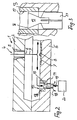
- a bullet channel 4 is arranged in the upper box part 2 and is connected to the molding material supply of the core molding machine.
- the bullet channel 4 is formed by a tubular body 5 made of a wear-resistant material which is embedded in the material of the core box upper part 2.
- an insert 7 made of a wear-resistant material is inserted into the core box wall on the side opposite the mouth 6 of the entry channel 4, the surface 8 of the insert 7 facing the mouth 6 corresponding in shape to the shape of the core part to be produced.
- additional insert pieces in the form of a pin 10 projecting into the mold space can be arranged, through the core to be produced or to be produced Mold depressions, for example core marks can be molded.
- the pin 10 is inserted in a recess in the base material of the lower box part 3 and its height can be adjusted precisely via a backing 11.
- the stream of molding material enters the interior of the mold at high speed and hits the surface 8 of the insert 7, where it is deflected so that the interior of the mold progressively fills completely with molding material. In this process, almost the entire amount of molding material filling the mold interior strikes the surface 8 of the insert 7.
- the molding material 10 also flows around the pins 10. Since the risk of wear essentially only exists on the pin 10 and in the area directly opposite the mouth 6, the surface area of the mold inner wall covered by the insert 7 need only be slightly larger than the projection of the entry opening 6 onto this part of the mold inner wall.
- one part or one core side has depressions such as are molded into the molding material with the aid of the pins 10 shown and described in FIG. 1.
- the other part or the other core side must have correspondingly assigned pin-shaped projections, which appear as a depression in the molding box. Since the molding material flows into such depressions with deflection and has to be compressed into the depressions, on the other hand, when the peg-shaped projection formed by the depression is moved with its surface relative to the shaping surface of the depression in the box part, this area is also exposed to high wear .
- the box parts here the box lower part 3 'are provided with a cup-shaped insert 12 made of wear-resistant material in this area, so that the dimensional accuracy of the cone-shaped projection to be molded is guaranteed over longer operating times. Since both the depression to be molded with the molding box according to FIG. 1 and the peg-shaped projection to be molded with the molding box according to FIG. 2 retain their dimensional stability unchanged even in the case of large quantities, the two core or molded parts to be produced can be inserted into one another accurately and without play, so that there is no offset between the two core or molded parts in the parting plane. The castings thus produced have practically no burr.
- the cup-shaped insert 12 in Fig. 2 is now designed so that it also forms a gas outlet nozzle. Accordingly, the insert 12 is divided into a tubular wall part 13 and a detachable base piece 14, which is a mushroom-shaped Head 15 has.
- the tubular wall part 13 has a shape cross section which does not have to be circular, but is shaped arbitrarily according to the requirements of the core to be manufactured or the associated core brand of the other part.
- the outer contour of the mushroom-shaped head 15 is dimensioned accordingly, the edge 16 of the head 15 facing the inner wall of the tubular part 13 running parallel and at a short distance from the inner wall 17.
- the width of the gap thus formed is, for example, only 0.2 mm.
- the space under the mushroom-shaped head is connected to a gas outlet 18, so that when the molding material is shot in, the gas can escape from the interior of the mold through the cup-shaped inserts 12 forming the gas outlet nozzles. This ensures that the peg-shaped projections to be formed on the core or molded part to be formed are fully formed and fully compressed.
- molded parts generally have a large number of gas outlet nozzles, but also a large number of core brands, the shape of the gas outlet nozzles described above also offers the possibility of simultaneously using them as ejectors.
- a shaft 19 connected to the base piece 14 is connected to a drive device 20. After the core box has been opened, the base pieces are moved in the direction of the mold interior via the drive 20 and the finished core can thus be detached from the mold and then removed.
- the use of the base piece 14 of the cup-shaped inserts 12 as ejectors is not limited to the exemplary embodiment shown.
- the special design of these outlet nozzles consists of a tubular part made of wear-resistant material and a base piece also made of wear-resistant material. This makes it possible to use such gas outlet nozzles as ejectors in which the top surface of the base piece lies in one plane with the adjacent surfaces of the mold inner wall. This has the advantage that the gas outlet nozzle cleans itself by the ejection process, but on the other hand it is ensured by the use of wear-resistant materials that molded material wedges wedged in the gap between the head piece and the wall of the insert piece practically do not lead to wear and thus to an expansion of the gas outlet gap to lead.
- FIG. 3 shows the design of such a gas outlet nozzle which can be actuated as an ejector on a larger scale.
- the shaft 19 connected to the head 15 has a stem-shaped design and has three or four wing-like projections 21, over which the base piece is guided in a centered manner, so that a constant gap width between the edge 16 and the inner wall 17 is ensured is.
- the inserts 5, 7, 10, 12 and also the bullet channel 4 are made of a non-deformable, wear-resistant material. Hard metals are preferably used for this purpose. The composition also depends on the wear and tear. The bullet channel 4 is subject to the highest stress.
Landscapes
- Engineering & Computer Science (AREA)
- Mechanical Engineering (AREA)
- Molds, Cores, And Manufacturing Methods Thereof (AREA)
- Moulds For Moulding Plastics Or The Like (AREA)
- Mounting, Exchange, And Manufacturing Of Dies (AREA)
Priority Applications (1)
| Application Number | Priority Date | Filing Date | Title |
|---|---|---|---|
| AT89200414T ATE78732T1 (de) | 1988-03-18 | 1989-02-14 | Formteil zur herstellung von formen fuer giessereizwecke mittels eines formstoffs, insbesondere kernkasten. |
Applications Claiming Priority (2)
| Application Number | Priority Date | Filing Date | Title |
|---|---|---|---|
| DE3809130 | 1988-03-18 | ||
| DE3809130A DE3809130A1 (de) | 1988-03-18 | 1988-03-18 | Formteil zur herstellung von formen fuer giessereizwecke mittels eines formstoffs, insbesondere kernkasten |
Publications (2)
| Publication Number | Publication Date |
|---|---|
| EP0338601A1 EP0338601A1 (de) | 1989-10-25 |
| EP0338601B1 true EP0338601B1 (de) | 1992-07-29 |
Family
ID=6350100
Family Applications (2)
| Application Number | Title | Priority Date | Filing Date |
|---|---|---|---|
| EP89200414A Expired - Lifetime EP0338601B1 (de) | 1988-03-18 | 1989-02-14 | Formteil zur Herstellung von Formen für Giessereizwecke mittels eines Formstoffs, insbesondere Kernkasten |
| EP89902257A Pending EP0357716A1 (de) | 1988-03-18 | 1989-02-14 | Formteil zur herstellung von formen für giessereizwecke mittels eines formstoffs, insbesondere kernkasten |
Family Applications After (1)
| Application Number | Title | Priority Date | Filing Date |
|---|---|---|---|
| EP89902257A Pending EP0357716A1 (de) | 1988-03-18 | 1989-02-14 | Formteil zur herstellung von formen für giessereizwecke mittels eines formstoffs, insbesondere kernkasten |
Country Status (8)
| Country | Link |
|---|---|
| US (1) | US5042562A (enExample) |
| EP (2) | EP0338601B1 (enExample) |
| JP (1) | JPH02501546A (enExample) |
| AT (1) | ATE78732T1 (enExample) |
| DE (2) | DE3809130A1 (enExample) |
| ES (1) | ES2034575T3 (enExample) |
| GR (1) | GR3006071T3 (enExample) |
| WO (1) | WO1989008513A1 (enExample) |
Families Citing this family (7)
| Publication number | Priority date | Publication date | Assignee | Title |
|---|---|---|---|---|
| GB2250226B (en) * | 1990-11-29 | 1994-08-31 | Honda Motor Co Ltd | Metallic mould for casting vehicle wheel |
| IT1396907B1 (it) * | 2009-05-22 | 2012-12-20 | Freni Brembo Spa | Attrezzatura per la realizzazione di anime da fonderia |
| JP6011370B2 (ja) * | 2013-01-30 | 2016-10-19 | マツダ株式会社 | 鋳型造型用金型の摩耗予測方法、摩耗予測装置及び摩耗予測プログラム |
| FR3011194B1 (fr) * | 2013-09-30 | 2017-05-26 | Peugeot Citroen Automobiles Sa | Dispositif de noyautage pour fonderie par gravite |
| CN104399879B (zh) * | 2014-11-12 | 2016-04-27 | 山西江淮重工有限责任公司 | 高精度组装铸造用芯盒 |
| JP6897538B2 (ja) * | 2017-12-14 | 2021-06-30 | トヨタ自動車株式会社 | 中子の造型方法及び造型装置 |
| DE202018107002U1 (de) * | 2018-04-12 | 2019-03-14 | Krämer + Grebe GmbH & Co. KG Modellbau | Vorrichtung zur Herstellung von Kernen aus Formstoff |
Family Cites Families (14)
| Publication number | Priority date | Publication date | Assignee | Title |
|---|---|---|---|---|
| US2347995A (en) * | 1941-10-06 | 1944-05-02 | Rock Ola Mfg Corp | Phonograph |
| US2510417A (en) * | 1948-04-28 | 1950-06-06 | Walter E Rehkiau | Foundry mold practice |
| US2659119A (en) * | 1950-06-15 | 1953-11-17 | Edwin F Peterson | Wear resisting insert for core making apparatus |
| US2807064A (en) * | 1953-06-25 | 1957-09-24 | Willard B Jay | Core box vent |
| US2800690A (en) * | 1955-12-20 | 1957-07-30 | Richard L Olson | Preventing erosion of core boxes opposite the blow holes thereof |
| US3103716A (en) * | 1961-01-03 | 1963-09-17 | Ford Motor Co | Core box |
| US3963209A (en) * | 1971-04-22 | 1976-06-15 | Muller Hans K | Ejector pin assembly for injection moulding tools |
| US3830284A (en) * | 1972-12-07 | 1974-08-20 | J Mindock | Blow tube with removable flange |
| DK134390B (da) * | 1974-10-23 | 1976-11-01 | Dansk Ind Syndikat | Fremgangsmåde ved isætning af kærner i en sandstøbeform. |
| FR2347995A1 (fr) * | 1976-04-14 | 1977-11-10 | Renault | Ejecteur filtre auto-decrassant |
| CH658007A5 (de) * | 1982-06-04 | 1986-10-15 | Fischer Ag Georg | Formeinrichtung zur herstellung einer giessform. |
| DE3620971A1 (de) * | 1985-02-14 | 1988-01-07 | Buchborn Stefan | Entlueftungsduese fuer giessereiwerkzeuge, insbesondere formkaesten u.dgl. |
| DE3720058A1 (de) * | 1987-06-16 | 1988-12-29 | Stefan Buchborn | Entlueftungsduese fuer giessereiwerkzeuge, insbesondere formkaesten u. dgl. |
| SU1491604A1 (ru) * | 1987-07-27 | 1989-07-07 | Научно-Производственное Объединение По Механизации И Автоматизации Производства Машин Для Хлопководства | Устройство дл изготовлени длинномерных стержней |
-
1988
- 1988-03-18 DE DE3809130A patent/DE3809130A1/de not_active Withdrawn
-
1989
- 1989-02-14 WO PCT/EP1989/000133 patent/WO1989008513A1/de not_active Ceased
- 1989-02-14 ES ES198989200414T patent/ES2034575T3/es not_active Expired - Lifetime
- 1989-02-14 EP EP89200414A patent/EP0338601B1/de not_active Expired - Lifetime
- 1989-02-14 US US07/444,125 patent/US5042562A/en not_active Expired - Lifetime
- 1989-02-14 EP EP89902257A patent/EP0357716A1/de active Pending
- 1989-02-14 JP JP1502074A patent/JPH02501546A/ja active Pending
- 1989-02-14 AT AT89200414T patent/ATE78732T1/de not_active IP Right Cessation
- 1989-02-14 DE DE8989200414T patent/DE58901915D1/de not_active Expired - Fee Related
-
1992
- 1992-10-26 GR GR920401769T patent/GR3006071T3/el unknown
Also Published As
| Publication number | Publication date |
|---|---|
| ATE78732T1 (de) | 1992-08-15 |
| DE3809130A1 (de) | 1989-10-05 |
| EP0357716A1 (de) | 1990-03-14 |
| WO1989008513A1 (fr) | 1989-09-21 |
| US5042562A (en) | 1991-08-27 |
| JPH02501546A (ja) | 1990-05-31 |
| EP0338601A1 (de) | 1989-10-25 |
| GR3006071T3 (enExample) | 1993-06-21 |
| ES2034575T3 (es) | 1993-04-01 |
| DE58901915D1 (de) | 1992-09-03 |
Similar Documents
| Publication | Publication Date | Title |
|---|---|---|
| DE2831292C2 (de) | Verfahren zur Herstellung eines verlorenen Kerns zum Gießen einer Turbinenschaufel | |
| EP0374346B1 (de) | Nadelverschlussdüse für Spritzgiessformen | |
| CH654768A5 (de) | Entgasungsvorrichtung an einer druck- oder spritzgiessform. | |
| DE4323038A1 (de) | Spritzdüse mit abnehmbarem vorderen Teil | |
| EP0210475B2 (de) | Verfahren und Vorrichtung zum Herstellen eines Spritzgiessteils | |
| DE4126041A1 (de) | Spritzgiessmaschine mit verdrehbaren, zu verschiedenen kombinationen zusammenstellbaren patrizen- und matrizen-einzelformen | |
| DE2640952C2 (de) | Verfahren zum KokillengieBen von Formgußteilen und Kokillensatz zur Durchführung des Verfahrens | |
| EP0338601B1 (de) | Formteil zur Herstellung von Formen für Giessereizwecke mittels eines Formstoffs, insbesondere Kernkasten | |
| DE69411558T2 (de) | Dichtungsvorrichtung für den einguss einer sandform | |
| DE10025489C2 (de) | Vorrichtung und Verfahren zur Herstellung von Metall-Keramik-Verbundwerkstoffen | |
| EP0152037B1 (de) | Verfahren und Vorrichtung zum Herstellen von Pressteilen aus duroplastischen Kunststoffen | |
| DE1604425A1 (de) | Metallene Gussform mit Abdampfstoepseln zum Formen von Plastikgegenstaenden und zum Vulkanisieren von Gummigegenstaenden | |
| EP0175691A1 (de) | Auskleidungsplatte für den formraum an formmaschinen | |
| DE3239838C2 (de) | Schließ- und Ansaugvorrichtung für in einem Angußkanal einer Spritzgießform verbleibende Schmelze | |
| DE102004028426B4 (de) | Einsatzkern und Verfahren zur Herstellung eines Zylinders für einen Verbrennungsmotor mit dem Einsatzkern | |
| DE3735735C2 (enExample) | ||
| DE3100463C2 (de) | Vorrichtung zum Druckgießen von Schaufelrädern | |
| EP2636467A2 (de) | Vorrichtung zur Herstellung eines Zylinderkurbelgehäuses in V-Bauform | |
| DE10114712C1 (de) | Vorrichtung zum Herstellen von Forminnen- oder außenteilen für Gießformen, wie Gießkernen | |
| EP0608518B1 (de) | Vorrichtung zum Entgraten von Formen und Kernen | |
| DE69314281T2 (de) | Kernführung für giessform und gusstück | |
| EP0661121A1 (de) | Auskleidungsplatte für Formkammern | |
| DE517376C (de) | Giessmaschine fuer fluessige oder plastische Massen, insbesondere fuer Schokolade | |
| DE2953635C1 (de) | Anlage zur Herstellung von Giessformen und Formkernen aus fliessfaehigen Formstoffen | |
| DE2524538A1 (de) | Spritzgiessform zum herstellen von gummi- oder kunststoffartikeln |
Legal Events
| Date | Code | Title | Description |
|---|---|---|---|
| PUAI | Public reference made under article 153(3) epc to a published international application that has entered the european phase |
Free format text: ORIGINAL CODE: 0009012 |
|
| AK | Designated contracting states |
Kind code of ref document: A1 Designated state(s): ES GR |
|
| 17P | Request for examination filed |
Effective date: 19891108 |
|
| XX | Miscellaneous (additional remarks) |
Free format text: VERBUNDEN MIT 89902257.8/0357716 (EUROPAEISCHE ANMELDENUMMER/VEROEFFENTLICHUNGSNUMMER) DURCH ENTSCHEIDUNG VOM 21.02.91. |
|
| 17Q | First examination report despatched |
Effective date: 19910411 |
|
| GRAA | (expected) grant |
Free format text: ORIGINAL CODE: 0009210 |
|
| RAP1 | Party data changed (applicant data changed or rights of an application transferred) |
Owner name: EB BRUEHL ALUMINIUMTECHNIK GMBH |
|
| AK | Designated contracting states |
Kind code of ref document: B1 Designated state(s): AT BE CH DE ES FR GB GR IT LI LU NL SE |
|
| REF | Corresponds to: |
Ref document number: 78732 Country of ref document: AT Date of ref document: 19920815 Kind code of ref document: T |
|
| XX | Miscellaneous (additional remarks) |
Free format text: VERBUNDEN MIT 89902257.8/0357716 (EUROPAEISCHE ANMELDENUMMER/VEROEFFENTLICHUNGSNUMMER) DURCH ENTSCHEIDUNG VOM 21.02.91. |
|
| REF | Corresponds to: |
Ref document number: 58901915 Country of ref document: DE Date of ref document: 19920903 |
|
| GBT | Gb: translation of ep patent filed (gb section 77(6)(a)/1977) | ||
| ET | Fr: translation filed | ||
| ITF | It: translation for a ep patent filed | ||
| REG | Reference to a national code |
Ref country code: ES Ref legal event code: FG2A Ref document number: 2034575 Country of ref document: ES Kind code of ref document: T3 |
|
| REG | Reference to a national code |
Ref country code: GR Ref legal event code: FG4A Free format text: 3006071 |
|
| PLBE | No opposition filed within time limit |
Free format text: ORIGINAL CODE: 0009261 |
|
| STAA | Information on the status of an ep patent application or granted ep patent |
Free format text: STATUS: NO OPPOSITION FILED WITHIN TIME LIMIT |
|
| 26N | No opposition filed | ||
| EPTA | Lu: last paid annual fee | ||
| EAL | Se: european patent in force in sweden |
Ref document number: 89200414.4 |
|
| REG | Reference to a national code |
Ref country code: GB Ref legal event code: IF02 |
|
| PGFP | Annual fee paid to national office [announced via postgrant information from national office to epo] |
Ref country code: GR Payment date: 20030214 Year of fee payment: 15 |
|
| PGFP | Annual fee paid to national office [announced via postgrant information from national office to epo] |
Ref country code: LU Payment date: 20030224 Year of fee payment: 15 Ref country code: GB Payment date: 20030224 Year of fee payment: 15 Ref country code: FR Payment date: 20030224 Year of fee payment: 15 Ref country code: DE Payment date: 20030224 Year of fee payment: 15 Ref country code: CH Payment date: 20030224 Year of fee payment: 15 |
|
| PGFP | Annual fee paid to national office [announced via postgrant information from national office to epo] |
Ref country code: AT Payment date: 20030227 Year of fee payment: 15 |
|
| PGFP | Annual fee paid to national office [announced via postgrant information from national office to epo] |
Ref country code: SE Payment date: 20030228 Year of fee payment: 15 Ref country code: NL Payment date: 20030228 Year of fee payment: 15 Ref country code: ES Payment date: 20030228 Year of fee payment: 15 |
|
| PGFP | Annual fee paid to national office [announced via postgrant information from national office to epo] |
Ref country code: BE Payment date: 20030311 Year of fee payment: 15 |
|
| PG25 | Lapsed in a contracting state [announced via postgrant information from national office to epo] |
Ref country code: LU Free format text: LAPSE BECAUSE OF NON-PAYMENT OF DUE FEES Effective date: 20040214 Ref country code: GB Free format text: LAPSE BECAUSE OF NON-PAYMENT OF DUE FEES Effective date: 20040214 Ref country code: AT Free format text: LAPSE BECAUSE OF NON-PAYMENT OF DUE FEES Effective date: 20040214 |
|
| PG25 | Lapsed in a contracting state [announced via postgrant information from national office to epo] |
Ref country code: SE Free format text: LAPSE BECAUSE OF NON-PAYMENT OF DUE FEES Effective date: 20040215 |
|
| PG25 | Lapsed in a contracting state [announced via postgrant information from national office to epo] |
Ref country code: ES Free format text: LAPSE BECAUSE OF NON-PAYMENT OF DUE FEES Effective date: 20040216 |
|
| PG25 | Lapsed in a contracting state [announced via postgrant information from national office to epo] |
Ref country code: BE Free format text: LAPSE BECAUSE OF NON-PAYMENT OF DUE FEES Effective date: 20040228 |
|
| PG25 | Lapsed in a contracting state [announced via postgrant information from national office to epo] |
Ref country code: LI Free format text: LAPSE BECAUSE OF NON-PAYMENT OF DUE FEES Effective date: 20040229 Ref country code: CH Free format text: LAPSE BECAUSE OF NON-PAYMENT OF DUE FEES Effective date: 20040229 |
|
| BERE | Be: lapsed |
Owner name: EB *BRUHL ALUMINIUMTECHNIK G.M.B.H. Effective date: 20040228 |
|
| PG25 | Lapsed in a contracting state [announced via postgrant information from national office to epo] |
Ref country code: NL Free format text: LAPSE BECAUSE OF NON-PAYMENT OF DUE FEES Effective date: 20040901 Ref country code: DE Free format text: LAPSE BECAUSE OF NON-PAYMENT OF DUE FEES Effective date: 20040901 |
|
| PG25 | Lapsed in a contracting state [announced via postgrant information from national office to epo] |
Ref country code: GR Free format text: LAPSE BECAUSE OF NON-PAYMENT OF DUE FEES Effective date: 20040903 |
|
| EUG | Se: european patent has lapsed | ||
| GBPC | Gb: european patent ceased through non-payment of renewal fee |
Effective date: 20040214 |
|
| REG | Reference to a national code |
Ref country code: CH Ref legal event code: PL |
|
| PG25 | Lapsed in a contracting state [announced via postgrant information from national office to epo] |
Ref country code: FR Free format text: LAPSE BECAUSE OF NON-PAYMENT OF DUE FEES Effective date: 20041029 |
|
| NLV4 | Nl: lapsed or anulled due to non-payment of the annual fee |
Effective date: 20040901 |
|
| REG | Reference to a national code |
Ref country code: FR Ref legal event code: ST |
|
| PG25 | Lapsed in a contracting state [announced via postgrant information from national office to epo] |
Ref country code: IT Free format text: LAPSE BECAUSE OF NON-PAYMENT OF DUE FEES;WARNING: LAPSES OF ITALIAN PATENTS WITH EFFECTIVE DATE BEFORE 2007 MAY HAVE OCCURRED AT ANY TIME BEFORE 2007. THE CORRECT EFFECTIVE DATE MAY BE DIFFERENT FROM THE ONE RECORDED. Effective date: 20050214 |
|
| REG | Reference to a national code |
Ref country code: ES Ref legal event code: FD2A Effective date: 20040216 |