EP0338339B1 - Sichtfenster für einen Schaltschrank oder einen Baugruppenträger - Google Patents
Sichtfenster für einen Schaltschrank oder einen Baugruppenträger Download PDFInfo
- Publication number
- EP0338339B1 EP0338339B1 EP89106094A EP89106094A EP0338339B1 EP 0338339 B1 EP0338339 B1 EP 0338339B1 EP 89106094 A EP89106094 A EP 89106094A EP 89106094 A EP89106094 A EP 89106094A EP 0338339 B1 EP0338339 B1 EP 0338339B1
- Authority
- EP
- European Patent Office
- Prior art keywords
- profile portion
- inspection window
- window according
- plate
- covering profile
- Prior art date
- Legal status (The legal status is an assumption and is not a legal conclusion. Google has not performed a legal analysis and makes no representation as to the accuracy of the status listed.)
- Expired - Lifetime
Links
Images

Classifications
-
- H—ELECTRICITY
- H02—GENERATION; CONVERSION OR DISTRIBUTION OF ELECTRIC POWER
- H02B—BOARDS, SUBSTATIONS OR SWITCHING ARRANGEMENTS FOR THE SUPPLY OR DISTRIBUTION OF ELECTRIC POWER
- H02B1/00—Frameworks, boards, panels, desks, casings; Details of substations or switching arrangements
- H02B1/26—Casings; Parts thereof or accessories therefor
- H02B1/30—Cabinet-type casings; Parts thereof or accessories therefor
- H02B1/306—Accessories, e.g. windows
Definitions
- the invention relates to a viewing window for an opening of a control cabinet or subrack with a U-shaped transparent pane made of a front plate and two side plates, which is connected to frame parts at least on the two end faces. (See DE-A-3 144 131)
- Such viewing windows are used to cover openings on a control cabinet or the opening on the front of a rack so that the components located in the area of the opening, such as display and operating elements, can be viewed.
- the viewing window can be firmly connected to the wall surrounding the opening or be articulated on this wall via a frame part, while the other frame part carries a closure with which the closed position of the viewing window can be locked.
- complicated and expensive frame parts are required for the viewing window, which also require considerable parts and assembly effort.
- the frame parts are each composed of a connecting profile section and a U-shaped cover profile section which can be snapped onto it, the lengths of which correspond to the clear distance between the side plates of the pane, that the connecting profile section has a receiving groove for plugging onto the front side of the front plate the disc has that the connecting section and the snapped cover profile section form a continuous longitudinal chamber and that corner pieces are provided with a receiving groove on the end faces of the side plates of the disc, which protrude into the longitudinal chamber of the frame parts with retaining lugs and are held therein.
- connecting profile sections need to be connected to the front plate of the pane.
- connection profile section and the cover profile section can be cut to length from a profile strand in the desired length, the adaptation to different sizes of the viewing window is not a problem.
- the corner pieces remain unchanged.
- the Ausgstaltung is made so that the connecting profile section consists of a base plate which carries on one long side the receiving groove formed by bends, that the opening of the receiving groove lies approximately in the plane of the base plate, and that the base plate in the area of the other long side a molded Has detent web with detent at the free end.
- a cover profile section which can be locked quickly and easily with this connecting profile section is characterized in that it overlaps with one side leg the angling of the receiving groove lying on the front of the front plate of the pane and engages behind its end face with a retaining web and in that the other side leg of the cover profile section has a snap-in receptacle for the latching approach of the locking web of the connecting profile section.
- the locking end position is determined by the fact that the cover profile section has an integrally formed support web on its inside, which is supported on the base bend of the receiving groove of the connection profile section and that the side leg with the locking receptacle of the cover profile section after locking with the locking web of the connection section on the base plate of the Supporting section section supports.
- a further embodiment it is provided from an aesthetic point of view that the front of the Disc facing edge between the side leg and the base leg of the cover profile section is chamfered and that this chamfer continues over the attached corner pieces. So that the beveled shape continues over the corner pieces, a further embodiment provides that the corner pieces on the sides facing the outside of the base leg of the cover profile section join flush and taper over the beveled transition area of the cover profile section and are bevelled accordingly.
- the cover profile section in the region of its base leg is extended beyond the side leg with the snap-in receptacle and has a bore, then an attachment option for hinges is created.
- a flush termination of the frame parts towards the pane is achieved in that the retaining web of the side leg of the cover profile section is flush with the inside of the base plate of the connection profile section facing away from the latching web after the cover profile section has snapped on.
- This conclusion is achieved up to the free edges of the side plates of the pane in that the base plate of the connecting profile section is extended beyond the latching web and over the extension with the through bore of the base leg of the cover profile section to the free edge of the side plates of the pane and is flush with it completes.
- the cover profile section does not always have to have a width which corresponds to the width of the side plates if the viewing window extends partially into the opening of the control cabinet or of the subrack.
- a further embodiment provides for aesthetic reasons that the outside of the base leg of the cover profile section has longitudinal grooves at regular intervals.
- the configuration is advantageously made in such a way that in the base leg of the cover profile section of the one frame part the closure is inserted, which has a locking cylinder with a locking bolt, that the locking bolt cooperates with a locking bolt fixed in a side wall delimiting the opening in such a way that in the extension of the base leg of the cover profile section of the other frame part bearing bolts for angular hinge parts are introduced, which are thus pivotally mounted on the cover profile section, and that the hinge parts are attached to a side wall delimiting the opening.
- the closure is inserted into a recess which can be introduced at any point on the base leg of the cover profile section.
- the hinge parts can be articulated in a simple manner on the cover profile section.
- the extension of the base leg of the cover profile section in the area of the hinges can also be left out if one wants to achieve a large swivel angle for the viewing window.
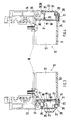
- FIG. 1 only the part of the subrack 15 around the front opening 16 is shown. It can be seen that the corner edges of the subrack 15 are chamfered.
- the vertically directed frame part is shown in the assembled position and attached to the pane 10, only the cover profile section 22 and the two corner pieces 30 being recognizable on the U-shaped, transparent pane 10.
- the disc 10 is formed by the front plate 11 and the two side plates 12 and 13, which are integrally connected to one another.
- the frame part is not yet attached to the left end face 14 of the pane 10. However, the parts are shown in an exploded view, which are required for the frame part.
- the connection profile section 17 is connected to the end face of the disk 10.
- the connecting profile section 17 is cut to a length which corresponds to the clear distance between the side plates 12 and 13 of the disc 10.
- the base plate 18 of the connecting profile section 17 faces the front Longitudinal edge on the receiving groove 20, which is formed by corresponding bends.
- the latching web 19 is molded onto the base plate 18 and has a continuous latching shoulder towards the associated long side.
- the base plate 18 is plugged with the receiving groove 20 onto the end face 14 of the front plate 11, whereby it is inserted into the area between the two side plates 12 and 13 and with the part extended beyond the latching web 19, flush with the free edges of the side plates 12 and 13 of the disc 10 completes.
- the front plate 11 can be fixed by gluing in the receiving groove 20 of the connecting profile section 17.
- the front plate 11 and the bends of the receiving groove 20 can also have aligned bores through which the two parts can be screwed or pinned together. If the connecting profile section 17 is fixed on the pane 10, then the corner pieces 30 are plugged onto the end faces 14 of the side plates 12 and 13. The sides of the corner pieces 30 facing the side plates 12 and 13 of the pane 10 likewise have receiving grooves for the side plates 12 and 13 which, as can be seen from FIG. 1, also extend to the free edges of the side plates 12 and 13. The corner pieces 30 plugged onto the side plates 12 and 13 are thus already held in the longitudinal direction of the connecting profile section 17. The U-shaped cover profile section 22 is then snapped onto the connection profile section 17.
- the front side leg 23 of the same runs out into the inwardly directed retaining web 24, which is placed on the end face of the outer bend 21 of the receiving groove 20 of the connecting profile section 17. Then the inner side leg 25 of the cover profile section 22 is snapped onto the latching web 19 of the connection profile section 17, as indicated in FIG. 2. The rest of the way externally projecting latching projection of the latching web 19 into the latching receptacle 26 which is continuous on the inside of the inner side leg 25.
- the continuous longitudinal chamber 37 (FIG. 4) is thus completed between the connection profile section 17 and the cover profile section 22.
- retaining lugs 32 are formed, which protrude into this longitudinal chamber 37 and are captively held therein transversely to the frame part after the locking of the connecting profile section 17 and cover profile section 22.
- the support web 28, which is formed on the inside of the base leg of the cover profile section 22, is supported on the base bending of the receiving groove 20 of the connection profile section 17.
- the inner side leg 25 also limits the snap-on movement of the cover profile section 22 by contacting the outside of the base plate 18 of the connecting profile section 17.
- the transition from the outer side leg 23 to the base leg of the cover profile section 22 is beveled, as the section according to FIG. 3 clearly shows. Therefore, the adjoining side 43 of the corner pieces 30 is also beveled accordingly.
- the side of the corner pieces 30 which is initially flush with the outside of the base leg of the cover profile section 22 merges into beveled transition sections 42 which, in the closed position of the viewing window, connect flush to the beveled corner edges of the subrack 15.
- the closure is introduced into the base leg of the cover profile section 22, which is provided on its outside with a number of longitudinally aligned grooves which are introduced at regular intervals.
- the cylinder lock 39 is inserted, which is inserted into the lock plate 27 and protrudes into the longitudinal chamber 37 of the frame part and carries the rotary latch 40 there.
- the rotary latch 40 is led out of the longitudinal chamber 37 via a recess in the inner side leg 25 of the cover profile section 22 and cooperates with the locking bolt 41, which is fixed to the side wall 33 of the subrack delimiting the opening 16.
- the articulation side of the viewing window is shown in section.
- the extension of the base leg of the cover profile section 22 can have bores 29 for hinge bolts 38 made at least in the two end sections. However, the bore 29 can also be continuous.
- Angular hinges 36 are fastened to the facing side wall 34 of the subrack, as the fastening point 35 indicates. These hinges 36 protrude into recesses of the extension of the base leg of the cover profile section 22 and carry aligned holes with the holes 29, so that the hinge bolts 38 inserted into the holes establish the articulated connection between the hinges 36 and the cover profile section 22 and thus the frame part with the viewing window can.
Landscapes
- Engineering & Computer Science (AREA)
- Power Engineering (AREA)
- Securing Of Glass Panes Or The Like (AREA)
- Fittings On The Vehicle Exterior For Carrying Loads, And Devices For Holding Or Mounting Articles (AREA)
- Liquid Crystal (AREA)
- Organic Low-Molecular-Weight Compounds And Preparation Thereof (AREA)
- Push-Button Switches (AREA)
Priority Applications (1)
| Application Number | Priority Date | Filing Date | Title |
|---|---|---|---|
| AT89106094T ATE83584T1 (de) | 1988-04-19 | 1989-04-07 | Sichtfenster fuer einen schaltschrank oder einen baugruppentraeger. |
Applications Claiming Priority (2)
| Application Number | Priority Date | Filing Date | Title |
|---|---|---|---|
| DE3813003 | 1988-04-19 | ||
| DE3813003A DE3813003C1 (ko) | 1988-04-19 | 1988-04-19 |
Publications (3)
| Publication Number | Publication Date |
|---|---|
| EP0338339A2 EP0338339A2 (de) | 1989-10-25 |
| EP0338339A3 EP0338339A3 (en) | 1989-12-20 |
| EP0338339B1 true EP0338339B1 (de) | 1992-12-16 |
Family
ID=6352313
Family Applications (1)
| Application Number | Title | Priority Date | Filing Date |
|---|---|---|---|
| EP89106094A Expired - Lifetime EP0338339B1 (de) | 1988-04-19 | 1989-04-07 | Sichtfenster für einen Schaltschrank oder einen Baugruppenträger |
Country Status (3)
| Country | Link |
|---|---|
| EP (1) | EP0338339B1 (ko) |
| AT (1) | ATE83584T1 (ko) |
| DE (2) | DE3813003C1 (ko) |
Families Citing this family (4)
| Publication number | Priority date | Publication date | Assignee | Title |
|---|---|---|---|---|
| DE3923104C1 (ko) * | 1989-07-13 | 1990-09-27 | Rittal-Werk Rudolf Loh Gmbh & Co Kg, 6348 Herborn, De | |
| US5639782A (en) * | 1992-03-04 | 1997-06-17 | Center For Innovative Technology | Neolignan derivatives as platelet activating factor receptor antagonists and 5-lipoxygenase inhibitors |
| FR2742595B1 (fr) * | 1995-12-19 | 1998-01-23 | Schneider Electric Sa | Enveloppe, notamment pour appareils electriques |
| DE29619481U1 (de) | 1996-11-11 | 1997-12-11 | Siemens AG, 80333 München | Baugruppenträger mit mindestens einer frontseitigen vertikalen Montagenut |
Family Cites Families (2)
| Publication number | Priority date | Publication date | Assignee | Title |
|---|---|---|---|---|
| DE3144131A1 (de) * | 1981-11-06 | 1983-05-19 | Licentia Patent-Verwaltungs-Gmbh, 6000 Frankfurt | Gehaeuse fuer ein geraet der steuer-, mess-, regel- oder datenverarbeitungstechnik |
| DE8236378U1 (de) * | 1982-12-24 | 1983-08-04 | Tehalit Kunststoffwerk Gmbh, 6751 Heltersberg | Kabelverzweigungsabdeckung |
-
1988
- 1988-04-19 DE DE3813003A patent/DE3813003C1/de not_active Expired
-
1989
- 1989-04-07 EP EP89106094A patent/EP0338339B1/de not_active Expired - Lifetime
- 1989-04-07 AT AT89106094T patent/ATE83584T1/de not_active IP Right Cessation
- 1989-04-07 DE DE8989106094T patent/DE58902990D1/de not_active Expired - Fee Related
Also Published As
| Publication number | Publication date |
|---|---|
| ATE83584T1 (de) | 1993-01-15 |
| DE58902990D1 (de) | 1993-01-28 |
| EP0338339A3 (en) | 1989-12-20 |
| DE3813003C1 (ko) | 1989-08-24 |
| EP0338339A2 (de) | 1989-10-25 |
Similar Documents
| Publication | Publication Date | Title |
|---|---|---|
| DE10053433C2 (de) | Schrank, insbesondere Geräteschrank | |
| DE4439607C1 (de) | Schaltschrank mit einem Rahmengestell | |
| EP0262450B1 (de) | Mehrzweck-Tischgehäuse | |
| DE2224327C3 (de) | Schrankmöbel mit wahlweiser Anordnung einer Rolljalousie oder einer Schwenktür | |
| DE4439628A1 (de) | Rahmengestell aus Rahmenschenkeln und Tiefenstreben | |
| EP0706012A1 (de) | Gargerät | |
| DE3828288C1 (ko) | ||
| DE9421839U1 (de) | Rahmengestell für einen Schaltschrank | |
| EP0818070B1 (de) | Schaltschrank mit rahmengestell und montageplatte | |
| EP0010763B1 (de) | Rahmenprofil für Fenster- und Türrahmen bzw. für aufsetzbare Bedienungsfelder od. dgl. von Schalt- oder Verteilerschränken und dgl. | |
| EP0338339B1 (de) | Sichtfenster für einen Schaltschrank oder einen Baugruppenträger | |
| EP0176890B1 (de) | Schaltschrank mit einem aus Rahmenschenkeln zusammengesetzten Rahmengestell | |
| WO1996027228A2 (de) | Schaltschrank mit rahmengestell und türelementen | |
| DE4013379C1 (en) | Electrical equipment cabinet with frame - divided into compartments by horizontal and vertical plates closable by section doors | |
| DE2517367B2 (de) | Beschlag für Kippschwenkflügel von Fenstern, Türen o.dgl | |
| DE4320322A1 (de) | Scharniereinrichtung für ein Dachflächenfenster | |
| EP0687786B1 (de) | Schiebetürbeschlag | |
| EP0922828A2 (de) | Fenster mit Vorsatzscheibe | |
| DE9115002U1 (de) | Gerätegehäuse mit zwei lösbar miteinander verbundenen Gehäuseteilen | |
| DE4336188C2 (de) | Schaltschrank mit Rahmengestell und Türelementen | |
| DE8805145U1 (de) | Sichtfenster für einen Schaltschrank oder einen Baugruppenträger | |
| DE4224888C1 (en) | Vehicle number-plate mounting - has deeper insertion groove between chamfered corners with insertion slits and hinging plate-supports locking in groove | |
| DE3312429C2 (de) | Kartenrahmen zur Aufnahme von Karten | |
| DE3906949C1 (en) | Withdrawal means for a switch cabinet | |
| DE3638407A1 (de) | Tuer fuer ein gehaeuse |
Legal Events
| Date | Code | Title | Description |
|---|---|---|---|
| PUAI | Public reference made under article 153(3) epc to a published international application that has entered the european phase |
Free format text: ORIGINAL CODE: 0009012 |
|
| AK | Designated contracting states |
Kind code of ref document: A2 Designated state(s): AT BE CH DE ES FR GB GR IT LI LU NL SE |
|
| PUAL | Search report despatched |
Free format text: ORIGINAL CODE: 0009013 |
|
| AK | Designated contracting states |
Kind code of ref document: A3 Designated state(s): AT BE CH DE ES FR GB GR IT LI LU NL SE |
|
| 17P | Request for examination filed |
Effective date: 19891107 |
|
| 17Q | First examination report despatched |
Effective date: 19920525 |
|
| GRAA | (expected) grant |
Free format text: ORIGINAL CODE: 0009210 |
|
| AK | Designated contracting states |
Kind code of ref document: B1 Designated state(s): AT BE CH DE ES FR GB GR IT LI LU NL SE |
|
| PG25 | Lapsed in a contracting state [announced via postgrant information from national office to epo] |
Ref country code: IT Free format text: LAPSE BECAUSE OF FAILURE TO SUBMIT A TRANSLATION OF THE DESCRIPTION OR TO PAY THE FEE WITHIN THE PRESCRIBED TIME-LIMIT;WARNING: LAPSES OF ITALIAN PATENTS WITH EFFECTIVE DATE BEFORE 2007 MAY HAVE OCCURRED AT ANY TIME BEFORE 2007. THE CORRECT EFFECTIVE DATE MAY BE DIFFERENT FROM THE ONE RECORDED. Effective date: 19921216 Ref country code: FR Effective date: 19921216 Ref country code: ES Free format text: THE PATENT HAS BEEN ANNULLED BY A DECISION OF A NATIONAL AUTHORITY Effective date: 19921216 Ref country code: SE Effective date: 19921216 Ref country code: GR Free format text: LAPSE BECAUSE OF FAILURE TO SUBMIT A TRANSLATION OF THE DESCRIPTION OR TO PAY THE FEE WITHIN THE PRESCRIBED TIME-LIMIT Effective date: 19921216 Ref country code: BE Effective date: 19921216 |
|
| REF | Corresponds to: |
Ref document number: 83584 Country of ref document: AT Date of ref document: 19930115 Kind code of ref document: T |
|
| REF | Corresponds to: |
Ref document number: 58902990 Country of ref document: DE Date of ref document: 19930128 |
|
| PG25 | Lapsed in a contracting state [announced via postgrant information from national office to epo] |
Ref country code: AT Effective date: 19930407 |
|
| GBT | Gb: translation of ep patent filed (gb section 77(6)(a)/1977) |
Effective date: 19930312 |
|
| PG25 | Lapsed in a contracting state [announced via postgrant information from national office to epo] |
Ref country code: LU Free format text: LAPSE BECAUSE OF NON-PAYMENT OF DUE FEES Effective date: 19930430 |
|
| EN | Fr: translation not filed | ||
| PLBE | No opposition filed within time limit |
Free format text: ORIGINAL CODE: 0009261 |
|
| STAA | Information on the status of an ep patent application or granted ep patent |
Free format text: STATUS: NO OPPOSITION FILED WITHIN TIME LIMIT |
|
| 26N | No opposition filed | ||
| PGFP | Annual fee paid to national office [announced via postgrant information from national office to epo] |
Ref country code: DE Payment date: 19940503 Year of fee payment: 6 |
|
| PG25 | Lapsed in a contracting state [announced via postgrant information from national office to epo] |
Ref country code: DE Effective date: 19960103 |
|
| REG | Reference to a national code |
Ref country code: GB Ref legal event code: IF02 |
|
| PGFP | Annual fee paid to national office [announced via postgrant information from national office to epo] |
Ref country code: GB Payment date: 20040324 Year of fee payment: 16 |
|
| PGFP | Annual fee paid to national office [announced via postgrant information from national office to epo] |
Ref country code: NL Payment date: 20040326 Year of fee payment: 16 Ref country code: CH Payment date: 20040326 Year of fee payment: 16 |
|
| PG25 | Lapsed in a contracting state [announced via postgrant information from national office to epo] |
Ref country code: GB Free format text: LAPSE BECAUSE OF NON-PAYMENT OF DUE FEES Effective date: 20050407 |
|
| PG25 | Lapsed in a contracting state [announced via postgrant information from national office to epo] |
Ref country code: CH Free format text: LAPSE BECAUSE OF NON-PAYMENT OF DUE FEES Effective date: 20050430 Ref country code: LI Free format text: LAPSE BECAUSE OF NON-PAYMENT OF DUE FEES Effective date: 20050430 |
|
| PG25 | Lapsed in a contracting state [announced via postgrant information from national office to epo] |
Ref country code: NL Free format text: LAPSE BECAUSE OF NON-PAYMENT OF DUE FEES Effective date: 20051101 |
|
| REG | Reference to a national code |
Ref country code: CH Ref legal event code: PL |
|
| GBPC | Gb: european patent ceased through non-payment of renewal fee |
Effective date: 20050407 |
|
| NLV4 | Nl: lapsed or anulled due to non-payment of the annual fee |
Effective date: 20051101 |